1
2.3.1 E2prom
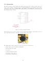
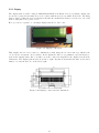
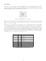
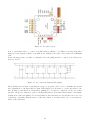
The memory we will be using in our clamp is BR24L08-W from Rohm. It has 8Kbit of memory that
can be used for storage, but this is very far from what we need for our authentication. In our case we
will only be using 1 register for storing a byte, that will be the same in the two E2proms of the clamp
and that will later on be used for authenticating the system.
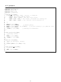
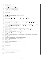
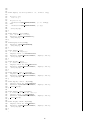
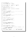
Figure 2.15: BR24L08-W e2prom memory
It is important to mention that we are using this E2prom not only because it’s specifications fit perfectly
with our project needs but also because it is specifically designed for working with i2c system, which
is the core of our project design.
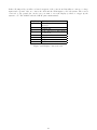
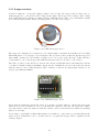
In the table below you will find a brief explanation of the connections in the memory. It is important
to mention that this memories have already set all the bits for adressing them but one, which is A2.
So to distinguish both memories we connected this pin to GND and Vcc respectively in each memory,
so that we can address them properly. A0 and A1 remain unconnected in this memories. Also the
write protect terminal is used for enabling or disabling the write in the memory, when is set to 0 and
1 respectively. In our design we set it to 0 as we believe that is inteligent to leave the write available
because if we set it to 1, once the board is welded and in the case of having any problem which required
rewritting the memory, we would have to buy a whole board.
Display pin
1
Name
A0
2
A1
3
A2
4
5
6
7
8
GND
SDA
SCL
WP
VCC
Description.
First bit for i2c memory addressing
Second bit for i2c memory addressing
Third bit for i2c memory addressing
Ground connection.
i2c serial data connection.
i2c serial clock connection.
Write protect terminal.
5 Volt input.
Figure 2.16: E2prom connection table
21