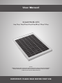
1
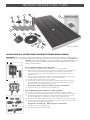
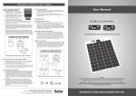
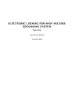
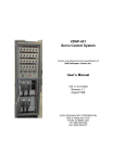
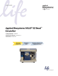
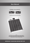
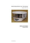
User Manual
SOLAR PANEL KITS
5wp/10wp/18wp/28wp/43wp/60wp/80wp/120wp/150wp
Models:
STP005/STP010/STP018/STP018MA/STP028/STP028MA/STP043/STP043MA/STPMH043/
STP060/STP060MA/STPMH060/STP080/STP080MA/STPMH080/STP120/STP120MA/
STPMH120/STP150/STP150MA/STPMH150
IMPORTANT: PLEASE READ BEFORE FIRST USE
SOLAR PANEL
KIT CONTENTS
TECHNICAL
HELPLINE
01684 774000
(Letters after item descriptions refer to the picture opposite)
STP005
1 x 5wp Solar Panel (a)
1 x 5m Cable (h)
1 x In line connector (i)
1 x In line fuse / holder (j)
2 x Crocodile clips (k)
6 x Ring terminals (l)
1 x Instruction sheet (m)
STP010
1 x 10wp Solar Panel (a)
1 x 5m Cable (h)
1 x In line connector (i)
1 x In line fuse / holder (j)
2 x Crocodile clips (k)
6 x Ring terminals (l)
1 x Instruction sheet (m)
STP018
1 x 18wp Solar Panel (a)
1 x 5m Cable (h)
1 x In line connector (i)
1 x In line fuse / holder (j)
2 x Crocodile clips (k)
6 x Ring terminals (l)
1 x Instruction sheet (m)
STP018MA
1 x 18wp Solar Panel (a)
1 x 4Ah voltage regulator (b)
1 x 5m Cable (h)
1 x In line connector (i)
1 x In line fuse / holder (j)
2 x Crocodile clips (k)
6 x Ring terminals (l)
1 x Instruction sheet (m)
STP028
1 x 28wp Solar Panel (a)
1 x 5m Cable (h)
1 x In line connector (i)
1 x In line fuse / holder (j)
2 x Crocodile clips (k)
6 x Ring terminals (l)
1 x Instruction sheet (m)
STP028MA
1 x 28wp Solar Panel (a)
1 x 4Ah voltage regulator (b)
1 x 5m Cable (h)
1 x In line connector (i)
1 x In line fuse / holder (j)
2 x Crocodile clips (k)
6 x Ring terminals (l)
1 x Instruction sheet (m)
STP043
1 x 43wp Solar Panel (a)
1 x 5m Cable (h)
1 x In line connector (i)
1 x In line fuse / holder (j)
2 x Crocodile clips (k)
6 x Ring terminals (l)
1 x Instruction sheet (m)
STP043MA
1 x 43wp Solar Panel (a)
1 x 4Ah voltage regulator (b)
1 x 5m Cable (h)
1 x In line connector (i)
1 x In line fuse / holder (j)
2 x Crocodile clips (k)
6 x Ring terminals (l)
1 x Instruction sheet (m)
STPMH043/PB
1 x 43wp Solar Panel (a)
1 x 4Ah voltage regulator (b)
4 x Aluminium fitting brackets (c)
(or 1 x 4pack of premium corner profiles
if PB kit has been selected)
16 x Stainless steel screws (d)
1 x Water resistant cable feed gland (e)
1 x Digital test meter (f)
1 x 300cc Tube of Sika Flex (g)
1 x 7m Cable (h)
1 x In line connector (i)
1 x In line fuse / holder (j)
2 x Crocodile clips (k)
6 x Ring terminals (l)
1 x Instruction sheet (m)
STP060
1 x 60wp Solar Panel (a)
1 x 5m Cable (h)
1 x In line connector (i)
1 x In line fuse / holder (j)
2 x Crocodile clips (k)
6 x Ring terminals (l)
1 x Instruction sheet (m)
STP060MA
1 x 60wp Solar Panel (a)
1 x 4Ah voltage regulator (b)
1 x 5m Cable (h)
1 x In line connector (i)
1 x In line fuse / holder (j)
2 x Crocodile clips (k)
6 x Ring terminals (l)
1 x Instruction sheet (m)
STPMH060/PB
1 x 60wp Solar Panel (a)
1 x 4Ah voltage regulator (b)
4 x Aluminium fitting brackets (c)
(or 1 x 4pack of premium corner
profiles if PB kit has been selected)
16 x Stainless steel screws (d)
1 x Water resistant cable feed gland (e)
1 x Digital test meter (f)
1 x 300cc Tube of Sika Flex (g)
1 x 7m Cable (h)
1 x In line connector (i)
1 x In line fuse / holder (j)
2 x Crocodile clips (k)
6 x Ring terminals (l)
1 x Instruction sheet (m)
STP080
1 x 80wp Solar Panel (a)
1 x 5m Cable (h)
1 x In line connector (i)
1 x In line fuse / holder (j)
2 x Crocodile clips (k)
6 x Ring terminals (l)
1 x Instruction sheet (m)
STP080MA
1 x 80wp Solar Panel (a)
1 x 8Ah voltage regulator (b)
1 x 5m Cable (h)
1 x In line connector (i)
1 x In line fuse / holder (j)
2 x Crocodile clips (k)
6 x Ring terminals (l)
1 x Instruction sheet (m)
STPMH080/PB
1 x 80wp Solar Panel (a)
1 x 8Ah voltage regulator (b)
4 x Aluminium fitting brackets (c)
(or 1 x 2pack of 52.5cm profiles if PB kit
has been selected)
16 x Stainless steel screws (d)
1 x Water resistant cable feed gland (e)
1 x Digital test meter (f)
1 x 300cc Tube of Sika Flex (g)
1 x 7m Cable (h)
1 x In line connector (i)
1 x In line fuse / holder (j)
2 x Crocodile clips (k)
6 x Ring terminals (l)
1 x Instruction sheet (m)
STP120
1 x 120wp Solar Panel (a)
1 x 5m Cable (h)
1 x In line connector (i)
1 x In line fuse / holder (j)
2 x Crocodile clips (k)
6 x Ring terminals (l)
1 x Instruction sheet (m)
STP120MA
1 x 120wp Solar Panel (a)
1 x 8Ah voltage regulator (b)
1 x 5m Cable (h)
1 x In line connector (i)
1 x In line fuse / holder (j)
2 x Crocodile clips (k)
6 x Ring terminals (l)
1 x Instruction sheet (m)
STPMH120/PB
1 x 120wp Solar Panel (a)
1 x 8Ah voltage regulator (b)
6 x Aluminium fitting brackets (c)
(or 1 x 4pack of premium corner profiles
and 1 x 2pack of 18cm profiles if PB kit
has been selected)
16 x Stainless steel screws (d)
1 x Water resistant cable feed gland (e)
1 x Digital test meter (f)
1 x 300cc Tube of Sika Flex (g)
1 x 7m Cable (h)
1 x In line connector (i)
1 x In line fuse / holder (j)
2 x Crocodile clips (k)
6 x Ring terminals (l)
1 x Instruction sheet (m)
STP150
1 x 150wp Solar Panel (a)
1 x 5m Cable (h)
1 x In line connector (i)
1 x In line fuse / holder (j)
2 x Crocodile clips (k)
6 x Ring terminals (l)
1 x Instruction sheet (m)
STP150MA
1 x 150wp Solar Panel (a)
1 x 12Ah voltage regulator (b)
1 x 5m Cable (h)
1 x In line connector (i)
1 x In line fuse / holder (j)
2 x Crocodile clips (k)
6 x Ring terminals (l)
1 x Instruction sheet (m)
STPMH150/PB
1 x 150wp Solar Panel (a)
1 x 12Ah voltage regulator (b)
6 x Aluminium fitting brackets (c)
(or 1 x 4pack of premium corner profiles
and 1 x 2pack of 18cm profiles if PB kit
has been selected)
16 x Stainless steel screws (d)
1 x Water resistant cable feed gland (e)
1 x Digital test meter (f)
1 x 300cc Tube of Sika Flex (g)
1 x 7m Cable (h)
1 x In line connector (i)
1 x In line fuse / holder (j)
2 x Crocodile clips (k)
6 x Ring terminals (l)
1 x Instruction sheet (m)
TECHNICAL HELPLINE 01684 774000
e
d
f
g
m
a
c
h
b
i
l
k
j
Kit shown: STPMH080
PLEASE READ ALL INSTRUCTIONS CAREFULLY BEFORE WORK BEGINS
IMPORTANT: When connecting a solar panel to a battery, it is always recommended that a voltage regulator is used to
prevent both reverse current feed (at night) and overcharging of the battery. The only exception to this is the STP005 and
STP010 because they are fitted with a reverse feed diode and if connected to battery size
at or greater than 35Ah and 70Ah respectively will not overcharge because of each
1A
B
battery’s own impedance.
Step 1: Fitting the cable to the solar panel
1.1 Remove the cover (A) from the terminal box on the rear of the Solar Panel
A
1.2 Panel sizes up to 28wp generally have the junction box style shown in Fig 1A. Panels 43wp
and over have the syle shown in Fig 1B. Fitting the cable to both is similar but with the
3 terminal style shown in Fig 1B you should ignore the centre terminal (L/H terminal is –ve
and R/H is +ve).
1.3 Take one end of the cable and strip back the black outer insulation 4.5cm. Strip back the
insulation of the red and black inner cables 1.5cm to expose bare wire.
1.4 Feed the cable through the hole in the terminal box.
1B
C
1.5 Twist the bare wire ends tightly and wrap clockwise around the loosened terminal screws
B or C (depending which junction box style you have). Alternatively, two ring terminals
(supplied) can be crimped onto the bare cable ends.
Red (positive), black (negative) as marked on inside of terminal box
1.6 Tighten terminal screws and replace the terminal box cover.
Step 2: Fitting the in-line connector to cable (optional)
This connector is supplied as a convenient means of desconnecting the panel from battery.
2.1 Decide where in te cable you would like to locate the in-line plug and socket. Cut the cable.
2
2.2 Strip back the black outer insulation of the cable connedted to the solar panel 2cm. Strip
back the insulation of the red and black inner cables 0.5cm to expose bare wire.
2.3 Remove the cover male plug (D) and remove the cover. Loosen the two terminal screws (E).
2.4 Twist the bare wire ends tightly and feed through the hole on the plug. Fit each wire end into
the correct terminal and tighten the clamp screw:
Red (positiv) = terminal 1 (E);
Black (negative) = terminal 2 (E)
2.5 Tighten terminal screws and replace cover.
2.6 Repeat precedure for the female socket (F)
TECHNICAL HELPLINE 01684 774000
������������������������������������������������
������������������������������������������������
Step
3: Connecting cables to Solar
voltage regulator
���������������������������
���������������������������
���� ����
(If
required)
�������������������������� � �������������������������������������������
��������������������������
�
�������������������������������������������
3
3.1�������������
Position
�������������
the solar voltage regulator
as�������������������
close as possible to the battery (must be a dry location)
�������������������
3.2 Measure the distance between your battery terminals and the solar voltage regulator.
���� ��������������������������������������������������
���� ������������������������������������������������� ���� ��������������������������������������������������
���� �������������������������������������������������
��������������������������������������������������
��������������������������������������������������
�������������������������������������������������
�������������������������������������������������
���������������������������������������������������
���������������������������������������������������
3.3 Cut the measured distance from the
end
of the cable, allowing some extra for slack.
���� ������������������������������������������
���� ������������������������������������������
����������������������������������������������
����������������������������������������������
������������������������������������������
������������������������������������������������
������������������������������������������������
3.4������������������������������������������
Prepare
as described in 2.2 the end
of
the cable from the in-line connector (if fitted) and attach to the
����������������������������������������������������
����������������������������������������������������
�����
����������������������������������������������
����� ����������������������������������������������
two
terminals (G) on the solar voltage
regulator.
���������������������������������������������������
���������������������������������������������������
������ ������
G G
H H
I
�������������������������������������������������
�������������������������������������������������
3.5 Take one end of the remaining cable,
prepare as above and attach to the centre terminals (H) on the
��������������
solar
voltage regulator by using the
same procedute as described in 1.5.
���������������������������������������������������
���������������������������������������������������
���� ��������������������������������������������������
���� ��������������������������������������������������
�������������������������������������������
�������������������������������������������
���� ��������������������������������������������
���� ��������������������������������������������
Note: Red = positive (+), black�����������������
= negative
����������������� (–)
����������
����������
4
���� ������������������������������������������������
���� ������������������������������������������������
��������������������������������������������� �������
���������������������������������������������
�������
Step
4: Fitting the fuse
�������������������������������������������������
�������������������������������������������������
������������������������������
������������������������������
������������������������
������������������������
4.1 Strip back the black outer insulation
of the cable 20cm.
�
�������
�
�������
�
���������������
�
���������������
��������������������
4.2��������������������
Cut
the red cable at the halfway point and strip 5mm of the red insulation from bogh the cut ends.
���������������������������������������������������
���������������������������������������������������
Twist the bare wire ends tightly.���������������������������������������������������������
Fit ���������������������������������������������������������
into the screw terminals (J) on each of the fuse holder pieces.
��������������������
��������������������
���������������������������������������������������
���������������������������������������������������
J
���������������������������������������������������
���������������������������������������������������
������������������������
������������������������
������������������������������������������������������������
������������������������������������������������������������
Step 5: Connecting the cable
to
your battery
���� ����������������������������������������������
���� ����������������������������������������������
�����������������������������������������������������
�����������������������������������������������������
�����������
������������������������������������������������������
������������������������������������������������������
5.1�����������
Strip
the red and black insulation
(3cm)
from te inner cable ends. Attach the cable to crocodile clips by
����������������������������������������������������������
the same procedure ����������������������������������������������������������
as
described
in 774000
1.5.774000
����following
�������������������������������������������������
���� �������������������������������������������������
0168401684
�������������������������������������������������������
�������������������������������������������������������
5
��������������������������������������������������
��������������������������������������������������
5.2�����������������������������������������������������
Alternatively,
for a more permanent connection to the battery, strip red and black insulation (6cm) from
�����������������������������������������������������
������������������������������������������������
������������������������������������������������
the
inner cable ends, twist the bare wire and wrap around the battery terminals and fix into position
�����������������������
�����������������������
using your battery clamps. Some clamps have connection screws fitted, in which case, if the supplied
�
���������������������
�
���������������������
ring
terminals
have
been
crimped
onto the wire ends, simply
attach using your battery clamp screws.
�����������������������
�����������������������
�������������������������������������������������������
�������������������������������������������������������
���������������������������������������������������������
���������������������������������������������������������
5.3���������������������
When connecting to a battery always
observe correct polarity.
���������������������
��������������������������������������������������������
��������������������������������������������������������
774000
0168401684
774000
����������������������������������������������������
���� �������������������������������������������������� ����������������������������������������������������
���� ��������������������������������������������������
���������������������������������������������������
���������������������������������������������������
������������������������������������������������������
������������������������������������������������������
Step 6: Additional information for fitting a MH kit
6.1 Attach the aluminium fitting brackets or premium profile (if PB kit has been selected) to the side of the panel using the supplied stainless steel
screws, ensuring the brackets are flush with the top of the panel frame (thereby leaving a gap between the bottom of the panel frame and
the roof).
���������������������������
���������������������������
permanent
fitting
is required
it isposition
When
permanent
is required
6.2When
Place
thefitting
panel
on
theit isroof
where it is to be fixed
����������������������������������
and draw ����������������������������������
a pencil
line around the footprint of the brackets or premium profile
�������������������������������������
�������������������������������������
��������������������������������������
��������������������������������������
(if PB kit has been selected). Ideally
the
panel should be fixed above the
cable
entry hole.
�������������������������������������
�������������������������������������
�������������������������������������
�������������������������������������
����������������������������������������
����������������������������������������
6.3 Clean the area on your motorhome,
caravan
or boat where each bracket
or premium profile (if PB kit has been selected) and the cable feed
�������������������������������������������
�������������������������������������������
�����������������������������������������
�����������������������������������������
��������������������������������������������
gland is to be fixed with spirit, and��������������������������������������������
make
sure the area is clean, oil free���������
and
dry.
���������
�������������������������������������
�������������������������������������
����������������������������
����������������������������
6.4 Insert the cable trailing from the solar
panel junction box into the cable feed gland, ensuring the locking nut is loose, and then into the entry
hole on the roof. Using the provided
Sika Flex, now bond the cable feed gland into position.
�������������������������������������������
�������������������������������������������
�������������������������������������
�������������������������������������
6.5 Apply the Sika Flex (around a 6mm
thickness
of Sika Flex is ideal) to the edge of each bracket or premium profile (if PB kit has been selected)
����������������������������������������
����������������������������������������
For more
information
kits please
For more
information
aboutabout
these these
kits please
and
then,
possibly
with
assistance,
turn
the panel so that the solar cells are facing upwards and bond the panel to the roof, positioning the
������������������������������������������
������������������������������������������
contact
your retailer
or Solar
Technology
at
contact
your retailer
or Solar
Technology
at
����������������������������������������
����������������������������������������
brackets inorthe
pencil
lines
previously
marked.
www.solartechnology
on 01684
774000.
www.solartechnology
on or
01684
774000.
����������������������������������������
����������������������������������������
��������������������������������������
��������������������������������������
6.6 Once the cable has been pulled through
the cable feed gland, the gland nut should be tightened to affect a water tight seal.
������������
������������
6.7 Now the cable can be channelled into the roof lining or into trunking/capping or similar and down to the battery. Finally, go to Steps 3, 4 and 5
to complete the installation.
NOTE – Sika Flex requires 24 hours to properly cure. We would therefore recommend that the motorhome, caravan or boat is not moved
during this period.
- 01684
774000.
SolarSolar
HelpHelp
Line Line
- 01684
774000.
Solar
Technology
International
Solar
Technology
International
Ltd. Ltd.
�����������������������������������
�����������������������������������
��������������������������������������������������������������������������
��������������������������������������������������������������������������
Unit
4 Station
Bredon
Unit
4
Station
DriveDrive
Bredon
GL20GL20
7HH 7HH
������������������������������������������������������������������
������������������������������������������������������������������
T:
01684
774000
F: 01684
773974
E: [email protected]
T:
01684
774000
F: 01684
773974
E: [email protected]
�������������������������
�������������������������
www.solartechnology.co.uk
www.solartechnology.co.uk
Options
Connecting an inverter into the system
7.1 Should you require your solar system to power 240v appliances, you will need to connect an inverter. Select an inverter power (measured in
watts) that is most appropriate for the power of your appliances (also measured in watts). The inverter will be ideally positioned reasonably close
to the battery. Most inverters come with pre-fixed cable so fix the loose end directly onto the battery terminals (positive to positive / negative to
negative) - contact 01684 774000 for more information.
Connecting two or more solar panels together
8.1 Should you wish to increase the power and make a solar array or increase the voltage (to produce 24volt instead of 12 volt) this can easily be
achieved. Please contact Solar Technology on 01684 774000 and request a copy of our “Creating a Solar Array” technical bulletin, which can
also be found in the ‘file download’ section at www.solartechnology.co.uk.
Adding a second battery
9.1 If a second battery is used, it can be connected to the Charge Controller, using terminals I (Fig. 3), by means of an additional piece of 2-core,
1mm cable (not supplied). As in step 4.6 above, attach the other cable to the second battery, not forgetting to add a fuse on the positive line as
descibed in step 5 above. Power from the Charge Controller will be diverted to the second battery only when the primary battery is fully charged.
Solar Technology International Ltd. Units 4-6, Station Drive,
Bredon, Nr. Tewkesbury, Gloucestershire GL20 7HH, United Kingdom
Telephone: 01684 774000 Fax: 01684 773974
E-mail: [email protected] Online: www.solartechnology.co.uk
Solar
TECHNOLOGY INTERNATIONAL