1
Cogent i.MXL LiteKit Hardware Reference Manual – Rev. 1.0 - 1/16/2006
Table of Contents
1 Warranty......................................................................................................................................................................................... 3
2 Overview ........................................................................................................................................................................................ 4
2.1 Introduction ............................................................................................................................................................................. 4
2.2 Reference Documents............................................................................................................................................................. 4
3 On Board Devices........................................................................................................................................................................... 5
3.1 CSB536FS Address Map......................................................................................................................................................... 5
3.2 8/16/32Mbyte STRATAFLASH ................................................................................................................................................ 5
3.3 64Mbyte SDRAM..................................................................................................................................................................... 5
3.4 Cirrus Logic CS8900a Ethernet Controller ............................................................................................................................... 5
3.5 ADS7846E 4-Wire Touch Controller ........................................................................................................................................ 6
3.6 Wolfson Microelectronics WM8731 I2S Codec ........................................................................................................................ 6
3.7 GPIO LED’s and Switches....................................................................................................................................................... 6
3.8 I2C LED’s and Switches .......................................................................................................................................................... 6
3.9 3.5” QVGA TFT LCD with Touch ............................................................................................................................................. 7
4 MC9328MXL On-Chip I/O Devices ................................................................................................................................................. 8
4.1 Overview ................................................................................................................................................................................. 8
4.2 MC9328MXL Chip Selects....................................................................................................................................................... 8
4.3 MC9328MXL General Purpose I/O Port Pin Assignments........................................................................................................ 8
4.4 MC9328MXL Interrupt Pin Assignments ................................................................................................................................ 12
4.5 MC9328MXL Debug UART ................................................................................................................................................... 13
4.6 MC9328MXL SPI Controller .................................................................................................................................................. 13
4.7 MC9328MXL I2C Interface .................................................................................................................................................... 13
4.8 MC9328MXL 4-Bit SD/MMC Controller.................................................................................................................................. 13
4.9 MC9328MXL Compact Flash................................................................................................................................................. 14
4.10 MC9328MXL USB Device Port ............................................................................................................................................ 14
4.11 TFT LCD Controller ............................................................................................................................................................. 14
5 Power and JTAG .......................................................................................................................................................................... 16
5.1 Overview ............................................................................................................................................................................... 16
5.2 3.3V Switching Regulator ...................................................................................................................................................... 16
5.3 Macraigor USBDemon........................................................................................................................................................... 16
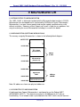
6 CSB536FS Software..................................................................................................................................................................... 17
6.1 Overview ............................................................................................................................................................................... 17
7 CSB536FS CPU Module Connectors, LED’s and Switches........................................................................................................... 18
7.1 Overview ............................................................................................................................................................................... 18
7.2 CSB536FS Expansion Connector.......................................................................................................................................... 18
7.3 CSB536FS Expansion Connectors........................................................................................................................................ 18
7.4 CSB536FS Expansion Connector Pinouts ............................................................................................................................. 19
7.5 CSB536FS Topside Connectors, LED’s and Switches........................................................................................................... 23
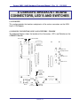
8 CSB935FS Breakout Board Connectors, LED’s and Switches ...................................................................................................... 24
8.1 Overview ............................................................................................................................................................................... 24
8.2 CSB935FS Connectors, LED’s and Switches - Topside ........................................................................................................ 24
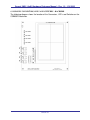
8.3 CSB935FS Connectors, LED’s and Switches – Backside ...................................................................................................... 25
9 Micromonitor................................................................................................................................................................................. 26
9.1 Introduction to Micromonitor .................................................................................................................................................. 26
9.2 Micromonitor Software Memory Map ..................................................................................................................................... 26
9.3 Connecting to Micromonitor................................................................................................................................................... 26
9.4 Micromonitor Commands....................................................................................................................................................... 27
9.5 Getting More Information about Micromonitor........................................................................................................................ 27
10 i.MXL LiteKit Schematics ........................................................................................................................................................... 28
List of Tables
Table 1 – CSB536FS Address Map ................................................................................................................................................... 5
Table 2 – MC9328MXL Chip Select Assignments.............................................................................................................................. 8
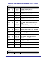
Table 3 – MC9328MXL GPIO Port A Pin Assignments ...................................................................................................................... 9
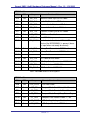
Table 4 – MC9328MXL GPIO Port B Pin Assignments .................................................................................................................... 10
Table 5 – MC9328MXL GPIO Port C Pin Assignments .................................................................................................................... 11
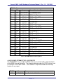
Table 6 – MC9328MXL GPIO Port D Pin Assignments .................................................................................................................... 12
Table 7 – CSB536FS/CSB925 Interrupt Pin Assignments................................................................................................................ 13
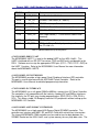
Table 8 – Compact Flash GPIO Assignments .................................................................................................................................. 14
Table 9 - Expansion Connector Mating Height Table ....................................................................................................................... 19
Table 10 – P1, Expansion Connector 1 Pinout................................................................................................................................. 21
Table 11 – P2, Expansion Connector 2 Pinout................................................................................................................................. 22
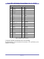
Table 12 – P3, Expansion Connector 3 Pinout................................................................................................................................. 23
PAGE 2