1
GigE Vision Area Scan Camera
™
CA-GENM-TSM00
www.teledynedalsa.com
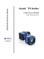
Genie TS Series
Camera User’s Manual
Genie TS Framework 1.00
© 2012 Teledyne DALSA
All information provided in this manual is believed to be accurate and reliable. No responsibility is assumed by
Teledyne DALSA for its use. Teledyne DALSA reserves the right to make changes to this information without
notice. Reproduction of this manual in whole or in part, by any means, is prohibited without prior permission having
been obtained from Teledyne DALSA.
Microsoft and Windows are registered trademarks of Microsoft Corporation in the United States and other
countries. Windows, Windows XP, Windows Vista, Windows 7 are trademarks of Microsoft Corporation.
All other trademarks or intellectual property mentioned herein belong to their respective owners.
Document Date: May 25, 2012
Document Number: CA-GENM-TSM00
*CA-GENM-TSM00*
About Teledyne DALSA
Teledyne DALSA is an international high performance semiconductor and electronics company that designs,
develops, manufactures, and markets digital imaging products and solutions, in addition to providing wafer foundry
services.
Teledyne DALSA Digital Imaging offers the widest range of machine vision components in the world. From
industry-leading image sensors through powerful and sophisticated cameras, frame grabbers, vision processors and
software to easy-to-use vision appliances and custom vision modules.
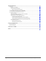
Contents
GENIE TS SERIES OVERVIEW ...............................................................................................................5
DESCRIPTION ............................................................................................................................................5
Genie Application Advantages..........................................................................................................6
PART NUMBERS AND SOFTWARE REQUIREMENTS.....................................................................................7
GIGE VISION SAPERA APPLICATION DESCRIPTION ...................................................................................8
CAMERA SPECIFICATIONS OVERVIEW .......................................................................................................9
Certifications...................................................................................................................................10
Vibration and Shock Certifications.................................................................................................10
GENIE TS SENSOR PERFORMANCE ..........................................................................................................11
DALSA DCK4131 Monochrome CMOS Sensor Specifications ......................................................11
Sensor Cosmetic Specifications: Teledyne DALSA DCK4131 Monochrome .................................12
Spectral Responsivity: Teledyne DALSA DCK4131 Monochrome .................................................13
Effective Quantum Efficiency: Teledyne DALSA DCK4131 Monochrome.....................................13
CONNECTING THE GENIE TS CAMERA ...........................................................................................15
GIGE NETWORK ADAPTER OVERVIEW ...................................................................................................15
PAUSE Frame Support ...................................................................................................................15
CONNECT THE GENIE TS CAMERA ..........................................................................................................15
Connectors ......................................................................................................................................16
LED Indicators ...............................................................................................................................16
Network Status Indicators ....................................................................................................................... 16
Camera Status LED Indicator.................................................................................................................. 17
LED States on Power Up ........................................................................................................................ 17
Genie IP Configuration Sequence ..................................................................................................18
Supported Network Configurations......................................................................................................... 18
PREVENTING OPERATIONAL FAULTS DUE TO ESD..................................................................................18
USING GENIE TS WITH SAPERA API .................................................................................................19
NETWORK AND COMPUTER OVERVIEW ...................................................................................................19
SAPERA LT LIBRARY WINDOWS INSTALLATION .....................................................................................20
GENIE TS FRAMEWORK INSTALLATION ..................................................................................................20
Procedure........................................................................................................................................20
Camera Firmware Updates ............................................................................................................20
Application Development Header Files ..........................................................................................21
GigE Server Verification.................................................................................................................21
GigE Server Status..........................................................................................................................21
OPTIMIZING THE NETWORK ADAPTER USED WITH GENIE .......................................................................22
Running the Network Configuration Tool.......................................................................................22
QUICK TEST WITH CAMEXPERT ..............................................................................................................23
About the User-Defined Camera Name ..........................................................................................24
SILENT INSTALLATION OF GENIE FRAMEWORK.......................................................................................25
WINDOWS EMBEDDED 7 INSTALLATION .................................................................................................26
OPERATIONAL REFERENCE................................................................................................................27
USING CAMEXPERT WITH GENIE TS CAMERAS ......................................................................................27
CamExpert Panes............................................................................................................................27
CamExpert View Parameters Option..............................................................................................29
CAMERA INFORMATION CATEGORY ........................................................................................................29
Genie_TS_Series GigE Vision Camera
Contents 1
Camera Information Feature Descriptions.....................................................................................30
SENSOR CONTROL CATEGORY ................................................................................................................32
Sensor Control Feature Descriptions .............................................................................................32
Gain and Black Level Control Details............................................................................................34
Exposure Controls Details ..............................................................................................................34
Free-running Programmable Exposure.................................................................................................... 34
External Trigger Programmable Exposure .............................................................................................. 35
Synchronization Timing ..................................................................................................................36
Synchronous Mode.................................................................................................................................. 36
Reset Mode ............................................................................................................................................. 36
I/O CONTROL CATEGORY .......................................................................................................................37
I/O Control Feature Descriptions...................................................................................................37
I/O Module Block Diagram..................................................................................................................... 41
Trigger Mode Details .............................................................................................................................. 41
Input Line Details.................................................................................................................................... 42
Output Line Details ................................................................................................................................. 42
Output Open and Output Close Modes.................................................................................................... 42
COUNTER AND TIMER CONTROL CATEGORY ..........................................................................................43
Counter and Timer Control Feature Description ...........................................................................43
Counter and Timer Group Block Diagram .............................................................................................. 46
Example: Counter Start Source = OFF.................................................................................................... 47
Example: Counter Start Source = CounterEnd (itself) ............................................................................ 47
Example: CounterStartSource = EVENT and Signal (Edge Base).......................................................... 48
Example: CounterStartSource = Signal (Level Base) Example 1 ........................................................... 48
Example: CounterStartSource = Line (Edge Base) Example 2 ............................................................... 49
ADVANCED PROCESSING CONTROL CATEGORY ......................................................................................49
Advanced Processing Control Feature Descriptions......................................................................50
Lookup Table (LUT) Overview .......................................................................................................53
Sharpness Type Overview ...............................................................................................................54
Flat Field Correction and Defective Pixel Detection Overview .....................................................54
Correction Function Block Diagram ....................................................................................................... 54
Flat Field Correction Algorithm Description .......................................................................................... 55
Information on the Sapera Flat Field Coefficients File ........................................................................... 55
Important Factors about Flat Field Processing ........................................................................................ 56
Defective Pixel Replacement .................................................................................................................. 56
Defective Pixel Detection Algorithm Description................................................................................... 56
How to do a FFC Setup via Sapera CamExpert .............................................................................56
Set up Dark and Bright Acquisitions with the Histogram Tool............................................................... 56
Flat Field Correction Calibration Procedure ........................................................................................... 58
Using Flat Field Correction..................................................................................................................... 60
IMAGE FORMAT CONTROL CATEGORY....................................................................................................61
Image Format Control Feature Description...................................................................................61
Width and Height Features for Partial Scan Control.....................................................................63
Vertical Cropping (Partial Scan) ............................................................................................................. 63
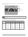
Maximum Frame Rate (fps) Examples (TS-M4096)............................................................................... 64
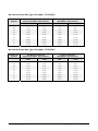
Maximum Frame Rate (fps) Examples (TS-M3500)............................................................................... 65
Maximum Frame Rate (fps) Examples (TS-M2500)............................................................................... 65
Horizontal Cropping (Partial Scan) ......................................................................................................... 66
Binning............................................................................................................................................67
Horizontal Binning Constraints............................................................................................................... 67
Vertical Binning Constraints ................................................................................................................... 67
Internal Test Image Generator .......................................................................................................68
METADATA CONTROL CATEGORY ..........................................................................................................69
Metadata Control Category Feature Descriptions .........................................................................69
ACQUISITION AND TRANSFER CONTROL CATEGORY...............................................................................70
Acquisition and Transfer Control Feature Descriptions ................................................................71
Acquisition Buffering.............................................................................................................................. 72
Start – End Command Requirements ...................................................................................................... 72
2 Contents
Genie_TS_Series GigE Vision Camera
Creating a Camera Configuration File in the Host .................................................................................. 72
EVENT CONTROL CATEGORY ..................................................................................................................72
Event Control Feature Descriptions ...............................................................................................73
Basic Exposure Events Overview ........................................................................................................... 75
Events Associated with Triggered Synchronous Exposures.................................................................... 76
Events Associated with Triggered Multiple Frame Synchronous Exposures.......................................... 76
Events Associated with Triggered Reset Mode Exposures ..................................................................... 77
GIGE VISION TRANSPORT LAYER CONTROL CATEGORY ........................................................................77
GigE Vision Transport Layer Feature Descriptions.......................................................................78
GIGE VISION HOST CONTROL CATEGORY ..............................................................................................83
FILE ACCESS CONTROL CATEGORY ........................................................................................................83
File Access Control Feature Descriptions......................................................................................84
File Access via the CamExpert Tool ...............................................................................................85
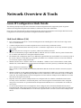
NETWORK OVERVIEW & TOOLS.......................................................................................................87
GENIE IP CONFIGURATION MODE DETAILS ............................................................................................87
Link-Local Address (LLA)...............................................................................................................87
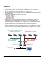
DHCP (Dynamic Host Configuration Protocol).............................................................................88
Persistent IP....................................................................................................................................89
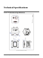
TECHNICAL SPECIFICATIONS............................................................................................................91
GENIE TS MECHANICAL SPECIFICATIONS ...............................................................................................91
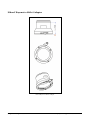
Nikon F Bayonet to M42x1 Adapter ...............................................................................................92
Genie TS Identification ...................................................................................................................93
Additional Notes on Genie TS Mechanical .....................................................................................93
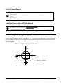
SENSOR ALIGNMENT SPECIFICATION ......................................................................................................93
CONNECTORS ..........................................................................................................................................94
25-pin Micro-D type Connector Details .........................................................................................94
Video Iris Connector Details ..........................................................................................................95
Iris Connector – Video Mode.................................................................................................................. 95
Iris Connector – DC Mode ...................................................................................................................... 95
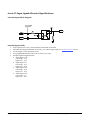
Genie TS Input Signals Electrical Specifications............................................................................96
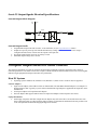
Genie TS Output Signals Electrical Specifications.........................................................................97
COMPUTER REQUIREMENTS FOR GENIE CAMERAS..................................................................................97
Host PC System...............................................................................................................................97
Ethernet Switch Requirements ........................................................................................................98
IEEE 802.3x Pause Frame Flow Control................................................................................................. 98
Ethernet to Fiber-Optic Interface Requirements ............................................................................98
EC & FCC DECLARATION OF CONFORMITY ...........................................................................................99
ADDITIONAL REFERENCE INFORMATION...................................................................................101
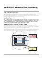
LENS SELECTION OVERVIEW ................................................................................................................101
Lens Mount Types .........................................................................................................................101
Lens for the Genie TS with M42 or Nikon F-mount......................................................................101
Additional Lens Parameters (application specific).......................................................................102
OPTICAL CONSIDERATIONS ...................................................................................................................102
Illumination...................................................................................................................................102
Light Sources ................................................................................................................................102
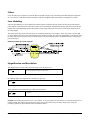
Filters............................................................................................................................................103
Lens Modeling...............................................................................................................................103
Magnification and Resolution.......................................................................................................103
SENSOR HANDLING INSTRUCTIONS .......................................................................................................104
Electrostatic Discharge and the Sensor........................................................................................104
Protecting Against Dust, Oil and Scratches .................................................................................104
Cleaning the Sensor Window ........................................................................................................104
RUGGEDIZED RJ45 ETHERNET CABLES.................................................................................................105
Genie_TS_Series GigE Vision Camera
Contents 3
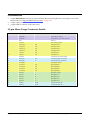
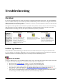
TROUBLESHOOTING............................................................................................................................107
OVERVIEW ............................................................................................................................................107
Problem Type Summary................................................................................................................107
Verifying Network Parameters......................................................................................................109
Before Contacting Technical Support ................................................................................................... 109
INSTALLATION ISSUES AND FUNCTIONAL PROBLEMS............................................................................109
The Windows XP Firewall Service Can Not Start ........................................................................109
DEVICE AVAILABLE WITH OPERATIONAL ISSUES ..................................................................................110
Firmware Updates ........................................................................................................................110
Power Failure During a Firmware Update–Now What? .............................................................110
Cabling and Communication Issues .............................................................................................110
Acquisition Error without Timeout Messages...............................................................................111
No camera exposure when expected ..................................................................................................... 111
Camera is functional but frame rate is lower than expected.................................................................. 111
Camera acquisition is good but frame rate is lower than expected........................................................ 111
Camera is functional, frame rate is as expected, but image is black ..................................................... 112
Other Problems or Issues..............................................................................................................112
Random Invalid Trigger Events ............................................................................................................ 112
Minimum Sapera Version Required ...................................................................................................... 112
CONTACT INFORMATION ..................................................................................................................113
SALES INFORMATION ............................................................................................................................113
TECHNICAL SUPPORT ............................................................................................................................114
GLOSSARY OF TERMS .........................................................................................................................115
INDEX........................................................................................................................................................119
4 Contents
Genie_TS_Series GigE Vision Camera
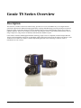
Genie TS Series Overview
Description
The Genie TS, a member of the Genie camera family, provides a new series of affordable easy to use digital cameras
specifically engineered for industrial imaging applications requiring embedded image processing and improved network
integration. Genie TS provides functions to increase dynamic range to ensure optimized image capture from a range of
lighting conditions. The TS series integrates features like motorized lens control, zoom and focus functionality, auto iris,
image compression, image transfer-on-demand, and both RS-485 and RS-232 ports.
Genie cameras combine standard gigabit Ethernet technology (GigE Vision 2.0 Compliant) with the Teledyne DALSA
Trigger-to-Image-Reliability framework to dependably capture and transfer images from the camera to the host PC. Genie
TS cameras are available in a number of models implementing different sensors and image resolutions, either in
monochrome or color versions.
Genie_TS_Series GigE Vision Camera
Genie TS Series Overview 5
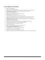
Genie Application Advantages
Optimized, rugged design
GigE Vision 2.0 compliant (pending)
Gigabit Ethernet (GigE) interconnection to a computer via standard CAT5e or CAT6 cables
Supports connection to the host computer NIC through a GigE network switch
Available in multiple resolutions
High frame rates with high resolutions
High dynamic range with support for a Multi-slope function
Digital binning for increased sensitivity
Auto-Brightness (Auto-exposure, Auto-gain (AGC), Auto-iris)
Supports cycling multiple exposure times for sequential images. along with other parameters
Multiple lookup table pre-processing for monochrome cameras, single for color versions
Multiple real-time shading corrections available with image cycling (i.e. Flat Field processing)
Horizontal and Vertical Flip function
Smoothing / Sharpening image filtering
Supports several trigger modes for image capture control including motion detection
Supports JPG image compression with user controlled parameters
4 general purpose inputs with programmable threshold
4 general purpose outputs
Supports auto iris and motorized zoom and focus lens control
Native Trigger-to-Image Reliability design framework
Visual status LEDs on camera back plate
1µs internal timer or external events can timestamp images
Supported by Sapera™ LT software libraries
Supports Power Over Ethernet and auxiliary power input
Refer to the Operation Reference and Technical Specifications section of the manual for full details
6 Genie TS Series Overview
Genie_TS_Series GigE Vision Camera
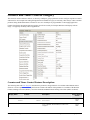
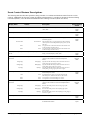
Part Numbers and Software Requirements
This manual covers the Genie TS monochrome models summarized below. Color Genie TS models and other lens mount
adapters will be added as per availability. See "Camera Specifications" on page 9 for each Genie TS model.
Camera
Resolution
Pixel size
Max fps
Lens Mounts
Product Number
TS-M4096
4096 x 3072
6.0 x 6.0 µm
12
M42 x 1mm treaded
G2-GM10-T4095
TS-M3500
3520 x 2200
6.0 x 6.0 µm
19
M42 x 1mm treaded
G2-GM10-T3505
TS-M2500
2560 x 2048
6.0 x 6.0 µm
29
M42 x 1mm treaded
G2-GM10-T2505
Genie Accessories & Cables (sold separately)
Order Number
Nikon F bayonet Adapter (see “Nikon F Bayonet to M42x1 Adapter” on page 92)
G2-AM42-MOUNT4
Genie TS I/O and Power breakout cable (25-pin Micro-D type connector)
G2-IOPC-MD25F
Optical filters such as NIR/UV blocking filers are available from Midwest Optical Systems.
Teledyne DALSA Software Platform
Genie TS Framework composed of the Sapera network Imaging Package, GeV Imaging Driver and latest
Genie TS Firmware. Required Microsoft Windows installation.
Included with Genie TS distribution
(via web download)
Sapera LT version 7.20 or later (for Windows)
includes Sapera Runtime and CamExpert
Provides everything you will need to develop imaging applications
Sapera documentation in compiled HTML help, and Adobe Acrobat® (PDF) formats.
Available for download
http://www.teledynedalsa.com/mv/
Linux Package for Genie TS
Contact Sales at Teledyne DALSA
Sapera Processing Imaging Development Library
(available for Windows or Linux - sold separately):
Contact Sales at Teledyne DALSA
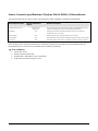
Third Party GigE Vision Software Platform Requirements
Support of GenICam GevApi version 2.0
General acquisition and control
Support of GenICam GevApi version 2.3
File access: firmware, LUT, FFC, configuration data, upload
& download
Support of GenICam XML schema version 1.1
Support of GigE Vision 1.2
Includes Chunk Metadata support version 1.2
support of GigE Vision 2.0
Jpeg payload type including chunk support of version 2.0
GenICam™ support — XML camera description file
Embedded within Genie
Genie_TS_Series GigE Vision Camera
Genie TS Series Overview 7
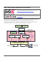
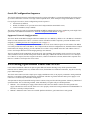
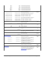
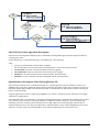
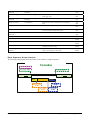
GigE Vision Sapera Application Description
Genie cameras are 100% compliant with the GigE Vision 1.2 and 2.0 specification which defines
the communication interface protocol used by any GigE Vision device. The device description
and capabilities are contained in an XML file. For more information see:
http://www.machinevisiononline.org/public/articles/index.cfm?cat=167
Genie cameras implement a superset of the GenICam™ specification which defines device
capabilities. This description takes the form of an XML device description file respecting the
syntax defined by the GenApi module of the GenICam™ specification. For more information see
www.genicam.org.
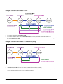
The Teledyne DALSA GigE Vision Module provides a license free development platform for Teledyne DALSA GigE
hardware or Sapera vision applications. Additionally supported are Sapera GigE Vision applications for third party hardware
with the purchase of a GigE Vision Module license, or the Sapera processing SDK with a valid license.
The GigE Vision Compliant XML device description file is embedded within Genie firmware allowing GigE Vision
Compliant applications access to Genie capabilities and controls immediately after connection.
User’s Sapera
Application
CamExpert
Sapera LT SDK
Network
Configuration Tool
Genie TS
Package
GigE Vision
Module
Images
Control
smart DHCP
Server (optional)
Sapera LT
GigE Server
Sapera Network
Imaging Driver
GVCP
GigE Vision
Control
Protocol
GVSP
GigE Vision
Stream
Protocol
Sapera
Network
Imaging
Module
Ethernet Network Interface Card
single GigE Vision
Camera
8 Genie TS Series Overview
Alternatively via a switch
To multiple GigE
Vision Cameras
Genie_TS_Series GigE Vision Camera
Camera Specifications Overview
Camera Controls
Synchronization Modes
Free running, External triggered, Software trigger through Ethernet
Exposure Modes
Programmable in increments of 1µs
minimum 19µs
maximum is 16 seconds
Pulse controlled via Trigger pulse width.
Trigger Inputs
Opto-isolated, 2.4V to 24V typical, 16mA min.
Debounce range from 0 up to 255 µs
Trigger Delay from 0 to 2,000,000 µs
Strobe Outputs
Output opto-isolated:
Aligned to the start of exposure with a programmable delay, duration and polarity
(using “start of exposure on output line source” feature)
Features
Flat Field Correction
2 Factory FFC plus 2 User Defined FFC
3x3 Kernel Sharpening Filter
4 Predefined Selections
LUT
Monochrome models: 4 LUT available
Binning
Digitally based: Horizontal (2 and 4 pixel) and Vertical (2 and 4 line)
Gain
Analog (analog gain steps are sensor dependent) and Digital gain up to 4x
Counter and Timer
1 Counter, and 1 Timer. User programmable, acquisition independent, with event generation.
Timestamp
1µs internal timer or external signal to timestamp images and events
Metadata Support
Also know as Chunk Data Support in SFNC
Test image
Internal generator with choice of static and shifting patterns, or user defined patterns uploaded with the file
access feature
User settings
Select factory default or either of two user camera configurations
Onboard Memory
Minimum Reserved Data Buffer
256 MB
Reserved Packet Resend Buffer
24 MB default (user defined feature)
Total Memory
512 MB
Back Focal Distance
M42 x 1 mount
Nikon F bayonet mount
12 mm
46.5 mm (34.5 mm for the F mount adapter plus 12 mm for the camera body)
Mechanical Interface
Camera Size
49(H) x 49(W) x 54(L) in mm, see “Genie TS Mechanical Specifications” on page 91
Mass
196 g (no lens)
Power connector
via 25-pin Micro-D connector, or RJ45 in PoE mode
Ethernet connector
RJ45
Electrical Interface
Input Voltage
+12 to +24 Volts DC (+20%/- 10%) at 0.6 Amp minimum
Supports the Power Over Ethernet standard. (PoE Class 0 as per IEEE 802.3af)
Power Dissipation
< 6W
Operating Temperature
-20 to 60°C
Relative Humidity
5% to 90% non-condensing (operating)
Output Data Configuration
Gigabit Ethernet with PAUSE Frame support (as per IEEE 802.3x)
Data and Control
GigE Vision compliant at 1000 or 100 Mbps
Genie_TS_Series GigE Vision Camera
Genie TS Series Overview 9
Specifications for each available sensor follow this section.
Certifications
CE
EN61000-4-2 : 2008
Electrostatic discharge immunity test
EN61000-4-3 : 2006 A1 : 2007 A2 : 2010 Radiated, radio-frequency, electromagnetic field immunity test
EN61000-4-4 : 2004
Electrical fast transient/burst immunity test
EN61000-4-5 : 2005
Surge immunity
EN61000-4-6 : 2008
Immunity to conducted disturbances, induced by radio-frequency fields
EN61000-4-8 : 2009
Power frequency magnetic field immunity
EN61000-4-11 : 2004
Voltage variations immunity
EN61000-6-2 : 2005
Electromagnetic immunity
EN61000-6-4: 2007
Electromagnetic emissions
CISPR 11: 2009 A1 : group 1 FCC, part 15, subpart B:2010
Limit: class A
Conducted Emissions
CISPR 22 : 2008
Limit: class A
LAN port Conducted Emissions
FCC
Part 15, class A
see "EC & FCC Declaration of Conformity" on page 99
RoHS
Compliancy as per European directive 2004/105/EC
Vibration and Shock Certifications
Test (while operating)
Test Levels
Test Parameters
Random vibrations
Level 1:
Level 2:
Level 3:
2 grms 60 min.
4 grms 45 min.
6 grms 30 min.
Frequency range: 5 to 2000 Hz
Directions: X, Y, and Z axes
Shocks
Level 1:
Level 2:
Level 3:
20 g / 11 ms
30 g / 11 ms
40 g / 60 ms
Shape: half-sine
Number: 3 shocks (+) and 3 shocks (-)
Directions: ±X, ±Y, and ±Z axes
10 Genie TS Series Overview
Genie_TS_Series GigE Vision Camera
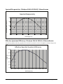
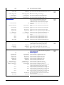
Genie TS Sensor Performance
The sensor description below provides a specification table and response graphics. The graph describes the sensor response
to different wavelengths of light (excluding lens and light source characteristics). Visible light spans wavelengths between
about 390 - 780 nanometers. Wavelengths below 390 nm are termed ultra-violet while those above 780 nm. are termed infrared.
DALSA DCK4131 Monochrome CMOS Sensor Specifications
Item / Feature
Specification
Sensor Model
Teledyne DALSA DCK4131 monochrome CMOS
Camera Models
TS-M4096, TS-M3500, TS-M2500
Minimum Frame Rate (free-running)
0.1 fps (one frame every 10 seconds)
Maximum Frame Rate (free-running)
Dependent on Genie TS model
Minimum Exposure
19 μs for any exposure mode
Maximum Exposure
16 s
Internal Trigger to Start of Exposure
106 μs
Horizontal Line Time
26.125 μs (TS-M4096), 22.925 μs (TS-M3500), 16.525 μs (TS-M2500)
Pixel Size
6.0µm x 6.0µm
Pixel Format
User selectable 8-bit or 10-bit
Shutter
Full frame electronic shutter
Sensor Gain Range
Default Gain value = 1.0, Selectable Gain = 2.65 (will vary dependant on Black Level Offset setting)
Full Well Capacity
32ke (typical)
Output Dynamic Range †
60db (typical) with Factory FFC Active
Signal to Noise ratio ††
45db (typical)
DN Variation
50% saturation: typical +/-4%
Responsivity
16 DN/(nJ/cm2) @ 560 nm (typical)
† Dynamic Range Test Conditions
Analog Gain 1x
Exposure 1500µs
Factory FFC Active
Defective Pixel Detection Active with Threshold at 5%
Averaging 10 frames
†† SNR Test Conditions
Analog Gain 1x
Exposure 750µs
Factory FFC Active
Defective Pixel Detection Active with Threshold at 5%
Averaging 10 frames at 50% saturation
Genie_TS_Series GigE Vision Camera
Genie TS Series Overview 11
Sensor Cosmetic Specifications: Teledyne DALSA DCK4131 Monochrome
The following table lists the current cosmetic specifications for models TS-M4096, TS-M3500, and TS-M2500
Blemish Specifications
Maximum Number of
Defects
Hot/Dead Pixel defects †††
Spot defects
Typical 0.015%
Max 0.05%
none
Blemish Description
Any pixel that deviates by ±20% from the average of neighboring pixels at 50%
saturation including pixel stuck at 0 and maximum saturated value.
Grouping of more than 8 pixel defects within a sub-area of 3x3 pixels, to a
maximum spot size of 7x7 pixels.
Clusters defects
none
Grouping of more than 5 single pixel defects in a 3x3 kernel.
Column defects
none
Vertical grouping of more than 10 contiguous pixel defects along a single column.
Row defects
none
Horizontal grouping of more than 10 contiguous pixel defects along a single row.
Note: All of the sensor cosmetic specifications are with factory flat-field correction (FFC) active and Dynamic Defective
Pixel Detection active. There are no pre-flat-field camera cosmetic specifications.
††† Test conditions
Factory FFC Active
Defective Pixel Detection OFF
Nominal light = illumination at 50% of saturation
Temperature of camera front plate is 45°C
12 Genie TS Series Overview
Genie_TS_Series GigE Vision Camera
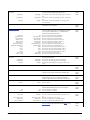
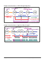
Spectral Responsivity: Teledyne DALSA DCK4131 Monochrome
Spectral Responsivity
Responsivity (DN/nJ/cm 2 )
20.0
15.0
10.0
5.0
0.0
400
500
600
700
800
900
1000
Wavelength (nm)
Effective Quantum Efficiency: Teledyne DALSA DCK4131 Monochrome
The following quantum efficiency graph describes the fraction of photons at each wavelength that contribute charge to the
pixel.
Effective Spectral Quantum Efficiency
60.0%
eff. QE [%]
50.0%
40.0%
30.0%
20.0%
10.0%
0.0%
400
450
500
550
600
650
700
750
800
850
900
Wavelength (nm)
Genie_TS_Series GigE Vision Camera
Genie TS Series Overview 13
This Page Intentionally Left Blank
14 Genie TS Series Overview
Genie_TS_Series GigE Vision Camera
Connecting the Genie TS Camera
GigE Network Adapter Overview
If the computer to be used with the Genie camera does not have a Gigabit network adapter or second built in Gigabit NIC, a
Gigabit Network Interface adapter card (NIC) needs to be installed. Typically under Windows, the Gigabit NIC is recognized
automatically when Windows boots.
An example of a high performance NIC is the Intel PRO/1000 MT adapter. Review the NIC documentation concerning any
special driver required for your specific operating system. Install the PCI bus Gigabit NIC as described by the NIC
manufacture's documentation.
PAUSE Frame Support
The Genie TS supports the Gigabit Ethernet PAUSE Frame feature as per IEEE 802.3x. PAUSE Frame is the Ethernet flow
control mechanism that temporarily stops data transmission on the network. The PAUSE Frame feature can help a NIC that
doesn’t have enough buffering to handle full-speed reception. This requires the flow control option in the NIC property
settings must be enabled.
Note that this problem is not as common with advances in computer bus speeds and memory sizes. PAUSE Frame support is
typically required to manage network traffic within a switch when multiple cameras are simultaneously used.
Connect the Genie TS Camera
Connecting a Genie TS to a network system is independent to whether the Teledyne DALSA Sapera LT package or a third
party GigE Vision development package is used.
Before connecting power to the camera, test all power supplies. Power supplies must meet the requirements defined in
section "Genie TS Input Signals Electrical " on page 96. Apply power to the camera.
Connect Genie to the host computer GigE network adapter or to the Ethernet switch via a CAT5e or CAT6 Ethernet
cable. Note: cable should not be less than 1 meter (3 feet) long or more than 100 meters (328 feet) long.
Once communication with the host computer is started the automatic IP configuration sequence will assign an LLA IP
address as described in section "Genie IP Configuration Sequence" on page 18, or a DHCP IP address if a DHCP server
is present on your network.
Check the diagnostic LED which will be initially red then switch to flashing blue while waiting for IP configuration. See
"Camera Status LED " on page 17 for Genie LED display descriptions.
The factory defaults for Genie is Persistent IP disabled and DHCP enabled with LLA always enabled as per the GigE
Vision specification. For additional information see "Genie IP Configuration Mode Details" on page 87. See the next
section "Connectors" on page 16 for an overview of the Genie interfaces.
Genie_TS_Series GigE Vision Camera
Connecting the Genie TS Camera 15
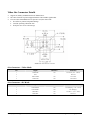
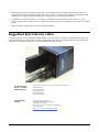
Connectors
The Genie has three connectors:
A single RJ45 Ethernet connector for control and video data transmitted to/from the host computer Gigabit NIC. The
Genie TS also supports Power Over Ethernet (PoE). See "Ruggedized RJ45 Ethernet Cables" on page 105 for secure
cables.
A Micro-D sub 25 connector for camera power (or auxiliary power), plus trigger, strobe and general I/O signals.
Teledyne DALSA provides an optional breakout cable (part number G2-IOPC-MD25F). See “25-pin Micro-D type
Connector Details” on page 94 for connector pinout specifications.
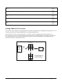
A 4-pin auto-iris connector pinout compatible with common DC and video iris lens.
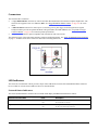
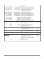
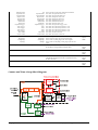
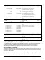
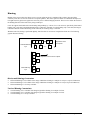
The following figure of the Genie back end shows connector and LED locations. See "Genie TS Mechanical Specifications"
on page 91 for details on the Genie connectors and camera mounting dimensions.
Genie – Rear View
LED Indicators
The Genie has one multicolor LED to provide a simple visible indication of camera state and the RJ45 Ethernet connector
has two LEDs for network status conditions. These are described below.
Network Status Indicators
The Genie TS RJ45 Ethernet connector has two LEDS which display standardized information as follows:
Ethernet Connector LEDs
Color
Left LED (Connection indicator)
Amber
Off
Right LED (Link/Activity indicator)
Green
Off
16 Connecting the Genie TS Camera
Description
Connected to a network
Not Connected to a network
Blinking – There is activity on the port
No data is currently being transferred
Genie_TS_Series GigE Vision Camera
Camera Status LED Indicator
The camera is equipped with one LED to display the operational status of the camera. When more than one condition is
active, the LED color indicates the condition with the highest priority (such as an acquisition in progress has more priority
than a valid IP address assignment).
Once the Genie is connected to a network, the Status LED will turn to steady blue when the IP address is assigned. Only at
this time will it be possible by the GigE Server or any application to communicate with the camera. The following table
summarizes the LED states and corresponding camera status.
LED State
Definition
LED is off
No power to the camera
Steady Red
Initial state on power up before flashing.
Remains as steady Red only if there is a fatal error. Camera is not initialized **
Slow Flashing Red
Initialization sequence in progress
**
In general there is no serious problem with the Genie hardware.
Wait a few minutes for the Genie to reboot itself.
Steady Red + Flashing Blue
Fatal Error. If the Genie TS does not reboot itself contact Technical Support.
Slow Flashing Blue
Ethernet cable disconnected. The camera continuously attempts to assign itself an IP address.
Fast Flashing Blue
File Access Feature is transferring data such as a firmware update, FCC or LUT transfer, etc.
Steady Blue
IP address assigned;
no application connected to the camera
Steady Green
Application connected
Flashing Green
Acquisition in progress. Flashing occurs on frame acquisition but does not exceed a rate of
100ms for faster frame rates.
Note: Even if the Genie has obtained an IP address, it might be on a different subnet than the NIC it is attached to. Therefore, if the Genie
LED is blue but an application can not see it, this indicates a network configuration problem. See the troubleshooting section in this manual.
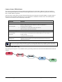
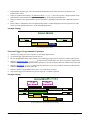
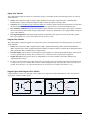
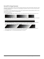
LED States on Power Up
The following LED sequence occurs when the Genie is powered up connected to a network with installed Genie Framework
software.
Red
power connected
Flashing Red
initialization
Genie_TS_Series GigE Vision Camera
Flashing Blue
waiting for IP
Blue
IP assigned
Green
application
connected
Connecting the Genie TS Camera 17
Genie IP Configuration Sequence
The Genie IP (Internet Protocol) Configuration sequence to assign an IP address is executed automatically on camera powerup or when connected to a network. As a GigE Vision compliant device, Genie attempts to assign an IP address as follows.
For any GigE Vision device, the IP configuration protocol sequence is:
Persistent IP (if enabled)
DHCP (if a DHCP server is present such as the Teledyne DALSA Smart DHCP server)
Link-Local Address (always enabled)
The factory defaults for Genie is Persistent IP disabled and DHCP enabled with LLA always enabled as per the GigE Vision
specification. For additional information see "Genie IP Configuration Mode Details" on page 87.
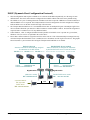
Supported Network Configurations
The Genie obtains an IP address using the Link Local Address (LLA) or DHCP, by default. A LLA IP address is obtained in
about 6 seconds with Microsoft Vista/7 or in about 1 minute with Microsoft XP. If required, a persistent IP address can be
assigned (see "Running the Network Configuration Tool" on page 22).
Preferably, a DHCP server is present on the network, where the Genie issues a DHCP request for an IP address. The DHCP
server then provides the Genie an IP address. The Teledyne DALSA Network Configuration tool, installed with the Teledyne
DALSA Network Imaging Package, provides a DHCP server which is easily enabled on the NIC used with the Genie TS
(refer to the Teledyne DALSA Network Imaging Package user's manual).
The LLA method, if used, automatically assigns the Genie with a randomly chosen address on the 169.254.xxx.xxx subnet.
After an address is chosen, the link-local process sends an ARP query with that IP onto the network to see if it is already in
use. If there is no response, the IP is assigned to the device, otherwise another IP is selected, and the ARP is repeated. Note
that LLA is unable to forward packets across routers.
Preventing Operational Faults due to ESD
Genie camera installations which do not protect against ESD (electrostatic discharge) may exhibit operational faults.
Problems such as random packet loss, random camera resets, and random loss of Ethernet connections, may all be solved by
proper ESD management.
The Genie camera when used with a simple power supply and Ethernet cable, is not properly connected to earth ground and
therefore is susceptible to ESD caused problems. An Ethernet cable has no ground connection and a power supply's 0 volt
return line is not necessarily connected to earth ground.
Teledyne DALSA has performed ESD testing on Genie cameras using an 8 kilovolt ESD generator without any indication of
operational faults. The two following methods, either individually or together will prevent ESD problems.
Method 1: Use a shielded power supply and/or Ethernet cable where the shield is connected to earth ground at the
supply end and to the Genie end. The Genie case is now properly connected to earth ground and can withstand ESD of 8
kilovolts, as tested by Teledyne DALSA.
Method 2: Mount the Genie camera on a metallic platform which has a good connection to earth ground.
18 Connecting the Genie TS Camera
Genie_TS_Series GigE Vision Camera
Using Genie TS with Sapera API
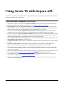
A Genie camera installation with Teledyne DALSA Sapera API generally follows the sequence described below. Detailed
installation instructions follow this overview.
Network and Computer Overview
Genie needs to connect to a computer with a GigE network adapter, either built in on the computer motherboard or
installed as a third party PCI adapter. See the previous section Connecting the Genie TS Camera.
Laptop computers with built in GigE network adapters may still not be able to stream full frame rates from Genie,
especially when on battery power. Thorough testing is required with any laptop computer to determine the maximum
frame rate possible (refer to the Teledyne DALSA Network Imaging Package user's manual).
Genie also can connect through a Gigabit Ethernet switch. When using VLAN groups, the Genie and controlling
computer must be in the same group (refer to the Teledyne DALSA Network Imaging Package user's manual).
If Genie is to be used in a Sapera development environment, Sapera LT needs to be installed, either before or after the
Genie software package. If Genie will be used in a GigE Vision Compliant environment, Sapera or Sapera runtime is not
required and you need to follow the installation instructions of the third party package.
Install the Genie Framework software package if not using a third party GigE Vision compliant package. Also install
Sapera Run-time with CamExpert to control the Genie.
The Windows Firewall exceptions feature is automatically configured to allow the Sapera GigE Server to pass through
the firewall.
Computers with VPN software (virtual private network) may need to have the VPN driver disabled in the NIC
properties. This would be required only on the NIC used with the Genie. Testing by the user is required.
Once a Genie is connected, look at the small camera icon added to the Windows tray (next to the clock). Ensure the
Genie camera has been found (right click the icon and select Status) Note that in Windows 7, the icon remains hidden
until a camera is connected.
A new Genie installation may require a firmware update. The File Selector feature is used to select a firmware file. See
the CamExpert procedure "File Access via the CamExpert Tool" on page 85 for additional information.
Use CamExpert (installed either with Sapera or Sapera runtime) to test the installation of the Genie camera. Set the
Genie to internal test pattern. See "Internal Test Image Generator" on page 68.
Set up the other components of the imaging system such as light sources, camera mounts, optics, encoders, trigger
sources, etc. Test with CamExpert.
Genie_TS_Series GigE Vision Camera
Using Genie TS with Sapera API 19
Sapera LT Library Windows Installation
Note: to install Sapera LT and the Genie device driver, logon to the workstation as an administrator or with an account that has
administrator privileges.
When Sapera application development is performed on the same computer that the Genie is connected to, the Sapera
Development Library (version 7.20 or later) must be installed. Else, Sapera LT SDK is not required to control the Genie
camera.
Download the Teledyne DALSA Sapera package or insert the Teledyne DALSA Sapera CD-ROM. Run the executable
file to start the installation.
The installation program will prompt you to reboot the computer.
Continue with the Genie TS Framework Installation described next.
Refer to Sapera LT User’s Manual concerning application development with Sapera.
Genie TS Framework Installation
The Genie TS Framework software package and Sapera runtime provides all components required to control the Genie with
the supplied CamExpert tool. The Genie TS Framework includes the Network Imaging package (refer to the Teledyne
DALSA Network Imaging package manual).
Do not install the Network Imaging package if a third-party GigE Vision network driver is used and the user does not need
CamExpert.
Note: The Teledyne DALSA Sapera CamExpert tool (used throughout this manual to describe Genie TS GigE Vision features) is installed
with either the Sapera LT runtime or the Sapera LT development package. If Sapera application development is required, install Sapera
(7.20 or later) as described in the previous section.
Procedure
Download the Genie TS Framework package and install the Genie Framework Software which includes the Network
Imaging driver, and the Sapera GigE server.
The procedure will prompt for acceptance of the installation folder for the Genie files.
Optional: If the Teledyne DALSA Sapera LT SDK package is not used, click to install Sapera LT run-time only which
includes CamExpert. Follow the on screen prompts and reboot when the installation is complete.
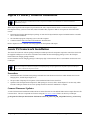
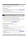
Camera Firmware Updates
A Genie TS Framework installation includes the latest camera firmware file. The default folder and an example firmware file
is shown below. The user can upload new firmware using the File Access Control features as shown by CamExpert.
[]:\Program Files\Teledyne DALSA\Genie TS\Firmwares\GenieTS_Mono-5M_8M_12M_STD-Firmware_3CA10.21.cbf
20 Using Genie TS with Sapera API
Genie_TS_Series GigE Vision Camera
Application Development Header Files
Teledyne DALSA provides header files for developers managing Genie TS LUT data and chunk payload data as supported
by GigE Vision 1.2. These files are installed by default in the folder [drv]:\Program Files\Teledyne DALSA\Genie
TS\Developer Support Files\.
These files are:
dalsa_genie_lut.h: Defines the structure for a user LUT data file.
dalsa_genie_chunk_payload.h: Used to capture the raw fields of the extended chunk metadata from the stream.
dalsa_genie_chunk_extract.h: This is passed the raw chunk data and fills in a data structure allowing access to the
metadata parameters.
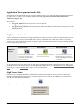
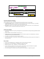
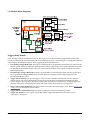
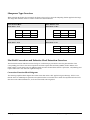
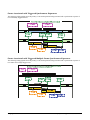
GigE Server Verification
After a successful Genie TS Framework package installation, the GigE Server icon is visible in the desktop taskbar tray area
(note that in Windows 7 the icon remains hidden until a camera is connected). After connecting a camera (see following
section), allow a few seconds for the GigE Server status to update. The Genie camera must be on the same subnet as the NIC
to be recognized by the GigE Server.
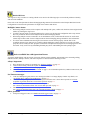
Device Available
Device IP Error
Device Not Available
The normal GigE server tray icon when
the Genie device is found. It will take a
few seconds for the GigE Server to
refresh its state after the Genie has
obtained an IP address.
The GigE server tray icon shows a
warning when a device is connected but
there is some type of IP error.
GigE Server
Tray Icon:
A red X will remain over the GigE server
tray icon when the Genie device is not
found. This indicates a major network
issue. Or in the simplest case, the Genie
is not connected.
If you place your mouse cursor on this icon, the GigE Server will display the number of GigE Vision devices found by your
PC. Right click the icon and select status to view information about those devices. See "Running the Network Configuration
Tool" on page 22 and "Troubleshooting" on page 107for more information.
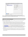
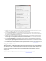
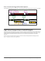
GigE Server Status
Once the Genie is assigned an IP address (its Status LED is steady blue) the GigE server tray icon will not have a red X
through it, indicating that the Genie device was found. It might take a few seconds for the GigE Server to refresh its state
after the Genie has obtained an IP address.
Right-click the GigE Server tray icon to open the following menu.
Genie_TS_Series GigE Vision Camera
Using Genie TS with Sapera API 21
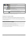
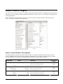
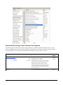
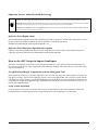
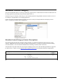
Click on Show Status to open a window listing all devices connected to the host system. Each GigE device is listed by name
along with important information such as the assigned IP address and device MAC address. The screen shot below shows a
connected Genie with no networking problems.
In the event that the device is physically connected, but the Sapera GigE Server icon is indicating that the connected device
is not recognized, click Scan Network to restart the discovery process. Note that the GigE server periodically scans the
network automatically to refresh its state. See "Troubleshooting" on page 107 for network problems.
Optimizing the Network Adapter used with Genie
Most Gigabit network interface controllers (NIC) allow user modifications to parameters such as Adapter Buffers and Jumbo
Frames. These should be optimized for use with the Genie during the installation. Refer to the Teledyne DALSA Network
Imaging package manual for optimization information.
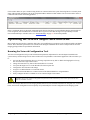
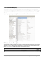
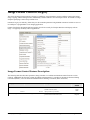
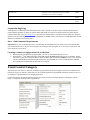
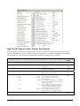
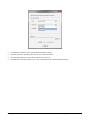
Running the Network Configuration Tool
The Network Configuration tool provides information and parameter adjustments for network adapters installed in the
system and any connected GigE Vision camera without use of any Windows Control Panel application. This tool allows you
to:
Activate the Network Imaging driver use for image acquisition on any NIC or disable the imaging driver for any
NIC not used with a GigE Vision camera.
Change the Auto Discovery Interval from the default of 15 seconds.
Verify that the GigE Server is in the Windows firewall exception list.
Configure the NIC and camera IP settings.
Assign a User-Defined name to a connected camera.
Assign a Persistent IP address to a camera instead of the default DHCP/LLA assigned address.
Easily Configure the NIC as a DHCP server for connected GigE Vision camera.
Important: Changes made with this tool may update Genie parameters stored in flash memory. Do not remove power from the Genie
camera for a minimum 10 seconds.
Refer to the Teledyne DALSA Network Imaging Module manual for more detailed information on using this tool. As shown
below, the Network Configuration tool can quickly verify and modify the network configuration of the imaging system.
22 Using Genie TS with Sapera API
Genie_TS_Series GigE Vision Camera
Run the tool from the Windows Start menu: Start•Programs•Teledyne DALSA Sapera Network Imaging Package•Dalsa
Network Configuration Tool. Verify the camera appears as a child of the NIC card it is connected to. By default the Genie
camera is identified by its serial number if no user-defined name has been assigned.
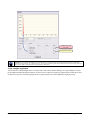
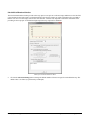
Quick Test with CamExpert
When the Genie TS camera is connected to a Gigabit network adapter on a host computer, testing the installation with
CamExpert is a straightforward procedure.
Start Sapera CamExpert by double clicking the desktop icon created during the Genie software installation.
CamExpert will search for installed Sapera devices. In the Device list area on the left side, the connected Genie camera
is shown or will be listed in a few seconds after CamExpert completes the automatic device search (device discovery).
Select the Genie camera device by clicking on the camera user-defined name. By default the Genie camera is identified
by its serial number. The Genie status LED will turn green, indicating the CamExpert application is now connected.
Click on the Grab button for live acquisition (the Genie default is Free Running mode). Focus and adjust the lens iris.
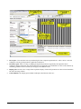
See "Operational Reference" on page 27 for information on CamExpert parameters with the Genie camera.
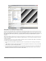
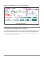
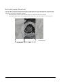
If the Genie has no lens, just select one of the internal test patterns available. All but one are static images to use with the
Snap or Grab function of CamExpert. The single “moving” test image is a shifting diagonal ramp pattern, which is
useful for testing network/computer bandwidth issues. The CamExpert feature selection and the grabbed pattern are
shown below.
Refer to the Teledyne DALSA Network Imaging package manual if error messages are shown in the Output Messages
pane. But first, increase the value of the Genie Interpacket Delay feature available from the GigE Vision Transport
Layer Category group in CamExpert. An increase from default may correct errors with NIC interfaces that do not have
adequate performance.
Genie_TS_Series GigE Vision Camera
Using Genie TS with Sapera API 23
About the User-Defined Camera Name
The Genie can be programmed with a user-defined name to aid identifying multiple cameras connected to the network. For
instance, on an inspection system with 4 cameras, the first camera might be labeled “top view”, the second “left view”, the
third “right view” and the last one “bottom view”. The factory default user name is set to match the camera serial number for
quick initial identification. Note that the factory programmed Genie TS serial number and MAC address are not user
changeable.
When using CamExpert, multiple Genie TS cameras on the network are seen as different "Genie_TS-xxxxx" devices as an
example. Non Teledyne DALSA cameras are labeled as “GigEVision Device”. Click on a device user name to select it for
control by CamExpert.
An imaging application uses any one of these attributes to identify a camera: its IP address, MAC address, serial number or
User Name. Some important considerations are listed below.
Do not use the camera's IP address as identification (unless it is a persistent IP) since it can change with each power
cycle.
A MAC address is unique to a single camera, therefore the control application is limited to the vision system with that
unique camera if it uses the camera's MAC address.
The User Name can be freely programmed to clearly represent the camera usage. This scheme is recommended for an
application to identify cameras. In this case, the vision system can be duplicated any number of times with cameras
identified by their function, not their serial numbers or MAC address.
24 Using Genie TS with Sapera API
Genie_TS_Series GigE Vision Camera
Silent Installation of Genie Framework
The Genie TS Framework installation can be integrated within a developer's installation procedure. The silent installation
mode allows the Genie Framework installation to proceed without the need for mouse clicks from a user.
Two steps are required:
Preparation of a response file to emulate a user.
Invoking the Genie Framework installer with command options to use the prepared response file.
Creating the Response File
An installer response file is created by performing a Genie Framework installation with the command line switch "-r". The
response file is automatically named setup.iss which is saved in the \windows folder. One simple method is to execute the
Framework installer from within a batch file. The batch file will have one command line.
As an example, using the possible executable file name for the Framework, the command line is:
"Genie_TS_1.00.00.0000 Release.exe" –r
Important: The executable name is enclosed in quotation marks. This is required because of the space characters in the Genie
Framework file name.
Running a Silent Mode Installation
A Genie Framework silent installation, whether done alone or within a larger software installation requires the Genie
Framework executable and the generated response file setup.iss.
Execute the Framework installer with the following command line:
"Genie_TS_1.00.00.0000 Release.exe" -s -f1".\setup.iss"
where in this example, the switch –f1".\setup.iss" specifies that the setup.iss file is in the same folder as the Framework
installer.
Genie_TS_Series GigE Vision Camera
Using Genie TS with Sapera API 25
Windows Embedded 7 Installation
Windows Embedded 7 is not officially supported by Teledyne DALSA due to the number of possible configurations.
However, Sapera LT and other Teledyne DALSA products should function properly on the Windows Embedded 7 platform
provided that the required components are installed.
Teledyne DALSA provides answer files (.xml) for use during Windows Embedded 7 installation that install all necessary
components for running Sapera LT 32-bit or 64-bit versions (SDK or Runtime), Sapera Processing 32-bit or 64-bit versions
(SDK or Runtime), Teledyne DALSA framegrabbers or Genie GigE Vision devices.
For each platform (32 or 64-bit), the answer file is provided:
SaperaGenie.xml: Configuration for Sapera LT, Sapera Processing and Teledyne DALSA Genie devices
These files are located in the following directories:
<Install Directory>\Sapera\Install\Win7_Embedded\Win32
<Install Directory>\Sapera\Install\Win7_Embedded\Win64
The OS footprint for these configurations is less than 1 GB. Alternatively, the Windows Thin Client configuration template
provided by Microsoft in the Windows Embedded 7 installation also provides the necessary dependencies for Sapera LT,
Teledyne DALSA framegrabbers and Genie devices (with an OS footprint of approximately 1.5 GB).
If you are installing other applications on the Windows Embedded 7 platform, it is recommended that you verify which
components are required, and if necessary, create a corresponding Answer File.
For more information on performing dependency analysis to enable your application on Windows Embedded 7, refer to the
Microsoft Windows Embedded 7 documentation.
26 Using Genie TS with Sapera API
Genie_TS_Series GigE Vision Camera
Operational Reference
Using CamExpert with Genie TS Cameras
The Sapera CamExpert tool is the interfacing tool for GigE Vision cameras, and is supported by the Sapera library and
hardware. When used with a Genie TS camera, CamExpert allows a user to test most of the operating modes. Additionally
CamExpert saves the Genie user settings configuration to the camera or saves multiple configurations as individual camera
parameter files on the host system (*.ccf).
An important component of CamExpert is its live acquisition display window which allows immediate verification of timing
or control parameters without the need to run a separate acquisition program.
Click on any parameter and a short description is displayed below the Category pane. The same context sensitive help is
button then click on a camera configuration parameter. Click on the
available by clicking on the
help file for more descriptive information on CamExpert.
button to open the
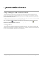
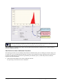
CamExpert Panes
The various areas of the CamExpert tool are described in the summary figure below. GigE Vision device Categories and
Parameter features are displayed as per the device’s XML description file. The number of parameters shown is dependent on
the View mode selected (Beginner, Expert, Guru – see description below).
Genie_TS_Series GigE Vision Camera
Operational Reference 27
Device pane: View and select from any installed GigE Vision or Sapera acquisition device. After a device is selected
CamExpert will only present parameters applicable to that device.
Parameters pane: Allows viewing or changing all acquisition parameters supported by the acquisition device.
CamExpert displays parameters only if those parameters are supported by the installed device. This avoids confusion by
eliminating parameter choices when they do not apply to the hardware in use.
Display pane: Provides a live or single frame acquisition display. Frame buffer parameters are shown in an information
bar above the image window.
Control Buttons: The Display pane includes CamExpert control buttons. These are:
28 Operational Reference
Genie_TS_Series GigE Vision Camera
Acquisition control button:
Click once to start live grab, click again to stop.
Single frame grab:
Click to acquire one frame from device.
Software trigger button:
With the I/O control parameters set to Trigger Enabled / Software Trigger type, click to send a
single software trigger command.
CamExpert display controls:
(these do not modify the frame buffer data)
Stretch (or shrink) image to fit, set image display to original size, or zoom the image to any size
and ratio. Note that under certain combinations of image resolution, acquisition frame rate, and
host computer speed, the CamExpert screen display may not update completely due to the host
CPU running at near 100%. This does not affect the acquisition.
Histogram / Profile tool:
Select to view a histogram or line/column profile during live acquisition.
Output pane: Displays messages from CamExpert or the GigE Vision driver.
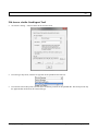
CamExpert View Parameters Option
All camera features have a Visibility attribute which defines its requirement or complexity. The states vary from Beginner
(features required for basic operation of the device) to Guru (optional features required only for complex operations).
CamExpert presents camera features based on their visibility attribute. CamExpert provides quick Visibility level selection
via controls below each Category Parameter list [ << Less More>> ]. The user can also choose the Visibility level from the
View · Parameters Options menu.
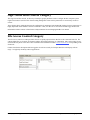
Camera Information Category
Camera information can be retrieved via a controlling application. Parameters such as camera model, firmware version, etc.
are read to uniquely identify the connected Genie device. These features are typically read-only. GigE Vision applications
retrieve this information to identify the camera along with its characteristics.
The Camera Information Category groups information specific to the individual GigE Vision camera. In this category the
number of features shown are identical whether the view is Beginner, Expert, or Guru.
Features listed in the description table but tagged as Invisible are usually for Teledyne DALSA or third party software
usage—not typically needed by end user applications.
Genie_TS_Series GigE Vision Camera
Operational Reference 29
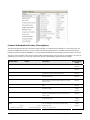
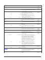
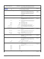
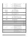
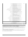
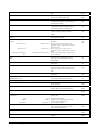
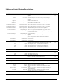
Camera Information Feature Descriptions
The following table describes these parameters along with their view attribute and in which device version the feature was
introduced. Additionally the Device Version column will indicate which parameter is a member of the DALSA Features
Naming Convention (using the tag DFNC), verses the GenICam Standard Features Naming Convention (SFNC not shown).
The Device Version number represents the camera software functional group, not a firmware revision number. As Genie TS
capabilities evolve the device version tag will increase, therefore identifying the supported function package.
Display Name
Feature
Description
Manufacturer Name
DeviceVendorName
Displays the device vendor name. (RO)
1.00
Beginner
Model Name
DeviceModelName
Displays the device model name. (RO)
1.00
Beginner
Device Version
DeviceVersion
Displays the device version. This tag will also highlight if
the firmware is a beta or custom design. (RO)
1.00
Beginner
Manufacturer Info
DeviceManufacturerInfo
This feature provides extended manufacturer information
about the device. (RO)
1.00
Beginner
Firmware Version
DeviceFirmwareVersion
Displays the currently loaded firmware version number.
Firmware files have a unique number and have the .cbf file
extension. (RO)
1.00
Beginner
Serial Number
DeviceID
Displays the device’s factory set camera serial number.
(RO)
1.00
Beginner
MAC Address
deviceMacAddress
Displays the unique MAC (Media Access Control) address
of the Device. (RO)
1.00
DFNC
Beginner
Device User ID
DeviceUserID
Feature to store a user-programmable identifier of up to 15
characters. The default factory setting is the camera serial
number. (RW)
1.00
Beginner
Device Built-In Self Test
deviceBIST
Command to perform an internal test which will determine
the device status. (W)
1.00
DFNC
Beginner
Device Built-In Self Test
Status
deviceBISTStatus
Determine the status of the device using the ‘Built-In Self
Test’. Possible return values are device-specific. (RO)
1.00
DFNC
Beginner
Passed
Last firmware update failed
30 Operational Reference
Passed
FirmwareUpdateFailure
Device Version
& View
No failure detected.
Last firmware update failed.
Genie_TS_Series GigE Vision Camera
Device Reset
DeviceReset
Resets the device to its power up state. (W)
1.00
Beginner
Power-up Configuration
Selector
UserSetDefaultSelector
Selects the camera configuration set to load and make active
on camera power-up or reset. The camera configuration sets
are stored in camera non-volatile memory. (RW)
1.00
Beginner
Factory Setting
UserSet1
Default
UserSet1
UserSet2
UserSet2
User Set Selector
UserSetSelector
Load factory default feature settings.
Select the user defined configuration UserSet 1 as the
Power-up Configuration.
Select the user defined configuration UserSet 2 as the
Power-up Configuration.
Selects the camera configuration set to load feature settings
from or save current feature settings to. The Factory set
contains default camera feature settings. (RW)
Factory Setting
Default
UserSet 1
UserSet1
UserSet 2
UserSet2
1.00
Beginner
Select the default camera feature settings saved by the
factory.
Select the User-defined Configuration space UserSet1 to
save to or load from features settings previously saved by
the user.
Select the User-defined Configuration space UserSet1 to
save to or load from features settings previously saved by
the user.
Load Configuration
UserSetLoad
Loads the camera configuration set specified by the User
Set Selector feature, to the camera and makes it active. (W)
1.00
Beginner
Save Configuration
UserSetSave
Saves the current camera configuration to the user set
specified by the User Set Selector feature. The user sets are
located on the camera in non-volatile memory. (W)
1.00
Beginner
Device Acquisition Type
deviceAcquisitionType
Displays the Device Acquisition Type of the product. (RO)
1.00
DFNC
Invisible
Sensor
Sensor
The device gets its data directly from a sensor.
DFNC Major Rev
deviceDFNCVersionMajor
Major revision of Dalsa Feature Naming Convention which
was used to create the device’s XML. (RO)
1.00
DFNC
Invisible
DFNC Minor Rev
deviceDFNCVersionMinor
Minor revision of Dalsa Feature Naming Convention which
was used to create the device’s XML. (RO)
1.00
DFNC
Invisible
SFNC Major Rev
DeviceSFNCVersionMajor
Major Version of the Standard Features Naming
Convention which was used to create the device's XML.
(RO)
1.00
Invisible
SFNC Minor Rev
DeviceSFNCVersionMinor
Minor Version of the Standard Features Naming
Convention which was used to create the device's XML.
(RO)
1.00
Invisible
SFNC SubMinor Rev
DeviceSFNCVersionSubMinor
SubMinor Version of the Standard Features Naming
Convention which was used to create the device's XML.
(RO)
1.00
Invisible
Genie_TS_Series GigE Vision Camera
Operational Reference 31
Sensor Control Category
The Genie TS sensor controls, as shown by CamExpert, groups sensor specific parameters. Parameters in gray are read only,
either always or due to another parameter being disabled. Parameters in black are user set in CamExpert or programmable via
an imaging application.
Features listed in the description table but tagged as Invisible are usually for Teledyne DALSA or third party software
usage—not typically needed by end user applications.
Sensor Control Feature Descriptions
The following table describes these parameters along with their view attribute and minimum camera firmware version
required. Additionally the firmware column will indicate which parameter is a member of the DALSA Features Naming
Convention (DFNC), verses the GenICam Standard Features Naming Convention (SFNC not shown).
Display Name
Feature
Description
Device Scan Type
DeviceScanType
Defines the scan type of the device’s sensor.
Genie TS is an Areascan camera. (RO)
Areascan
Sensor Color Type
Areascan
sensorColorType
Monochrome Sensor
Bayer Sensor
Input Pixel Size
pixelSizeInput
32 Operational Reference
Sensor color type is monochrome.
Sensor color type is Bayer.
Size of the image input pixels, in bits per pixel. (RO)
Bpp8
Bpp10
1.00
Beginner
Device uses an Areascan sensor.
Defines the camera sensor color type. (RO)
Monochrome
CFA_Bayer
8 Bits/Pixel
10 Bits/Pixel
Device Version
& View
Sensor output data path is 8 bits per pixel.
Sensor output data path is 10 bits per pixel.
1.00
DFNC
Beginner
1.00
DFNC
Guru
Genie_TS_Series GigE Vision Camera
Sensor Width
SensorWidth
Defines the sensor width in active pixels. (RO)
1.00
Expert
Sensor Height
SensorHeight
Defines the sensor height in active lines. (RO)
1.00
Expert
Acquisition Frame Rate
AcquisitionFrameRate
Specifies the camera internal frame rate, in Hz.
Note that any user entered value is automatically adjusted
to a valid camera value.
1.00
Beginner
Auto-Exposure
ExposureAuto
Sets the automatic exposure mode when the
ExposureMode feature is set to Timed. (RO)
1.00
Beginner
Off
Off
Once
Once
Continuous
Continuous
Exposure duration is manually controlled using the
ExposureTime feature.
Exposure duration is calculated once by the device to
meet the auto-brightness target pixel value. After it has
converged, it returns to the Off state.
Exposure duration is constantly adapted by the camera to
meet the auto-brightness target pixel value.
Auto-Exposure Time Max
Value
exposureAutoMaxValue
Sets the maximum exposure time value allowed by the
user, in microseconds, for the Auto-Exposure function.
(RO)
1.00
DFNC
Beginner
Auto-Exposure Time Min
Value
exposureAutoMinValue
Sets the minimum exposure time value allowed by the
user, in microseconds, for the Auto-Exposure function.
(RO)
1.00
DFNC
Beginner
Exposure Mode
ExposureMode
Sets the operation mode for the camera’s exposure (or
shutter). (RO)
1.00
Beginner
Timed
Timed
The exposure duration time is set using the Exposure
Time feature and the exposure starts with a FrameStart
event.
Exposure Delay
exposureDelay
Specifies the delay in microseconds (µs) to apply after the
FrameStart event before starting the ExposureStart event.
1.00
DFNC
Beginner
Exposure Time
ExposureTime
Sets the exposure time (in microseconds) when the
Exposure Mode feature is set to Timed.
1.00
Beginner
Exposure Alignment
exposureAlignment
Exposure Alignment specifies how the exposure is
executed in relationship to the sensor capabilities and
current frame trigger.
1.00
DFNC
Beginner
Synchronous
Synchronous
Reset
Reset
Black Level Selector
BlackLevelSelector
Analog
Exposure is synchronous to the internal timing of the
sensor. The readout is concurrent to the exposure for the
fastest possible frame rate. When a valid trigger is
received and the ExposureTime is shorter than the
readout period, the ExposureStart event is latched in the
previous frame’s readout. That is; the
ExposureStartEvent is delayed and is initiated when the
actual exposure starts such that the exposure ends and
readout begins as soon as the previous readout has
completed.
Sensor timing is reset to initiate exposure when a valid
trigger is received. Readout is sequential to exposure,
reducing the maximum achievable frame rates. That is, a
trigger received during exposure or readout is ignored
since data would be lost by performing a reset.
Selects which Black Level to adjust using the Black
Level features.
AnalogAll
1.00
Beginner
Sensor Dark Offset
Black Level (in DN)
BlackLevel
Controls the black level as an absolute physical value.
This represents a DC offset applied to the video signal, in
DN (digital number) units. The Black Level Selector
feature specifies the channel to adjust.
1.00
Beginner
Gain Selector
GainSelector
Selects which gain is controlled when adjusting gain
features.
1.00
Beginner
Genie_TS_Series GigE Vision Camera
Operational Reference 33
Analog
AnalogAll
Digital
DigitalAll
Apply an analog gain adjustment within the sensor to the
entire image.
Apply a digital gain adjustment to the entire image.
Gain
Gain
Sets the selected gain as an amplification factor applied to
the image.
1.00
Beginner
MultiSlope Sensor Response
Mode
multiSlopeSensorResponseMode
Sets the enable state of the multislope response
mechanism on the sensor. (RO)
Disable the MultiSlopeSensorResponseMode feature.
1.00
DFNC
Beginner
Off
Off
Acquisition Frame Rate (Raw)
AcquisitionFrameRateRaw
Controls the desired frame rate of the camera
in .001 Hz.
1.00
Invisible
Black Level RAW
BlackLevelRaw
Controls the black level as an absolute physical value.
1.00
Invisible
Gain and Black Level Control Details
The Genie TS series of cameras provide gain and black level adjustments. Dependent on the model of camera, adjustments
are available at the sensor as an analog variable and/or in the digital domain. The gain and black level controls can make
small compensations to the acquisition in situations where lighting varies and the lens iris can not be easily adjusted. Optimal
gain and black level adjustments maximizes the Genie TS dynamic range for individual imaging situations. The user can
evaluate Gain and Black Level by using CamExpert.
Features and limitations are described below.
Black Level offset is expressed as a digital number providing a +/- offset from the factory setting. The factory setting
optimized the black level offset for maximum dynamic range under controlled ideal dark conditions.
Analog Gain is expressed as a multiplication factor applied at the sensor level, before any FFC. The increased gain
increases the sensor dynamic range but with a non-proportional increase in noise.
For each setting of analog gain, the sensor data has applied a unique Factory set Flat Field Correction, to ensure uniform
pixel response. which is applied after the analog gain stage but before the digital gain stage.
When any Flat Field Correction is applied, the resulting gain multiplying factor is increased based on the FFC
calibration. As an example with Genie TS-12M with FFC Active and default Black Offset, with an analog gain set to
2.65, the resulting multiplying factor is 2.75.
Digital Gain is expressed as a multiplication factor applied after the Analog Gain and any FFC stages, but note that
increasing digital gain does not increase the low level resolution and increases the sensor noise proportionately.
Exposure Controls Details
Exposure Control modes define the method and timing of controlling the sensor integration period. The integration period is
the amount of time the sensor is exposed to incoming light before the video frame data is transmitted to the controlling
computer.
Exposure control is defined as the start of exposure and exposure duration.
The feature Exposure Mode selects the controlling method for the exposure.
The start of exposure can be an internal timer signal (free-running mode), an external trigger signal, a software function
call trigger.
The exposure duration can be programmable (such as the case of an internal timer) or controlled by the external trigger
pulse width.
Free-running Programmable Exposure
Genie TS is in a multifunctional free running mode with the following features:
34 Operational Reference
Genie_TS_Series GigE Vision Camera
Programmable internal trigger, where the maximum and minimum sensor frame rate limits are defined by the
ExposureTime feature.
Exposure synchronization timing is "Synchronous Mode" (on page 36) where the exposure is aligned with the sensor
horizontal line timing and the next acquisition is triggered by an internal programmable timer.
Exposure duration is user programmable (exposure maximum is dependent on the frame rate). Minimum exposure is
19µs.
Image readout is simultaneous where the grabbed image frame is readout during the next frame exposure time. This
allows for fastest possible frame rates. See the timing diagram below.
Example Timing:
Free-running Exposure Timing
External Trigger Programmable Exposure
Also known as “Edge Pre-select” exposure. See the timing diagram below.
An external trigger edge initiates the exposure process.
The user programmable delay (exposureDelay) from valid trigger edge to start of exposure is camera model specific.
Supports "Synchronous Mode" (on page 36) timing for fastest possible frame rates. Start of exposure is aligned on the
next horizontal line while the exposure duration period is in 1µs steps. Exposure and sensor readout can be concurrent.
Supports "Reset Mode" (on page 36) timing. Exposure duration is in 1µs steps. Exposure and sensor readout must be
sequential, limiting the maximum frame rate.
Exposure duration is programmable from 19μs to 16 seconds (with 1μs steps).
Any external trigger received before the previous exposure is complete is ignored.
Example Timing
FrameTrigger Inactive
FrameTrigger Inactive
FrameTrigger Active
Frame Inactive
Frame Inactive
Exposure
Delay
Exposure(1)
ReadOut (1)
Exposure
Delay
Exposure(2)
ReadOut (2)
Programmable Synchronous Mode Exposure Timing
Genie_TS_Series GigE Vision Camera
Operational Reference 35
exposureAlignment=Reset
Input Signal
Event
Input Signal
Event (2)
ValidFrameTrigger
Event
TriggerDelay
Invalid Frame Trigger Period
FrameTrigger Inactive
FrameTrigger Active
FrameTrigger Inactive
FrameActive (1)
Frame Inactive
Exposure
Delay
Exposure(1)
TriggerDelay
Invalid Frame Trigger Period
FrameTrigger Active
FrameActive (2)
Frame Inactive
ReadOut (1)
Exposure
Delay
Exposure(2)
Programmable Reset Mode Exposure Timing
Synchronization Timing
Genie TS supports two types of sensor synchronization used to align the exposure to sensor timing:
Synchronous Mode: Exposure is synchronous to the line timing of the sensor. Exposure time steps are 1µs and the
readout can be concurrent to the exposure for the fastest possible frame rate.
Reset Mode: Timing is reset to initiate exposure of the next frame. Exposure time steps are 1µs, but readout must be
sequential to exposure, reducing the maximum achievable frame rate.
Synchronous Mode
Synchronous mode starts the exposure period aligned to the sensor horizontal line timing and the programmable duration
steps are 1µs.
Exposure duration is from a minimum of 19µs up to 16 sec.
In this mode, sensor exposure and sensor readout of the previous frame's exposure occur simultaneously. This allows
operating the sensor up to its maximum frame rate.
Any trigger received before the end of the exposure is ignored.
Since the external trigger is asynchronous with the Genie horizontal line timing, the frame exposure start is subject to 1
horizontal line jitter.
Reset Mode
Exposure starts immediately after a valid trigger. There is no jitter on the start of exposure.
Exposure time is user programmable or controlled by the trigger pulse width.
Minimum exposure is 19µs – maximum is 16 seconds, with steps of 1µs.
Sensor readout must complete before the next exposure can start. That is, exposure and readout are sequential.
Therefore, the maximum frame rate is lower than for Synchronous mode.
Any external trigger received before the previous exposure/read out sequence is completed, is ignored.
36 Operational Reference
Genie_TS_Series GigE Vision Camera
I/O Control Category
The Genie TS I/O controls, as shown by CamExpert, groups features used to configure external inputs and acquisition
actions based on those inputs, plus camera output signals to other devices. Parameters in gray are read only, either always or
due to another parameter being disabled. Parameters in black are user set in CamExpert or programmable via an imaging
application.
Features listed in the description table but tagged as Invisible are usually for Teledyne DALSA or third party software
usage—not typically needed by end user applications.
I/O Control Feature Descriptions
The following table describes these features along with their view attribute and minimum camera firmware version required.
Additionally the firmware column will indicate which parameter is a member of the DALSA Features Naming Convention
(DFNC), verses the GenICam Standard Features Naming Convention (SFNC not shown).
Display Name
Feature
Description
Trigger Selector
TriggerSelector
Selects which type of trigger to configure with the
various Trigger features.
Genie_TS_Series GigE Vision Camera
Device Version
& View
1.00
Beginner
Operational Reference 37
Single Frame Trigger(Start)
MultiFrame Trigger(Start)
Trigger Mode
FrameStart
FrameBurstStart
TriggerMode
Off
On
Selects a trigger starting the capture of a single frame.
Selects a trigger to capture multiple frames. The number
of frames is specified by the triggerFrameCount feature.
Controls the enable state of the selected trigger.
Off
On
The selected trigger is turned off.
The selected trigger is turned active.
1.00
Beginner
Trigger Frames Count
triggerFrameCount
Sets the total number of frames to acquire when a valid
trigger is received. This feature is available when the
Trigger Selector is set to MultiFrames Trigger or Motion
Detection Trigger. The trigger frame count includes the
number of frames specified in the Pre-Trigger Frame
Count feature.
1.00
DFNC
Beginner
Software Trigger
TriggerSoftware
Generate a software command internal trigger
immediately no matter what the TriggerSource feature is
set to.
1.00
Beginner
Trigger Source
TriggerSource
Specifies the internal signal or physical input line to use
as the trigger source. The selected trigger must have its
TriggerMode set to ON.
1.00
Beginner
Line 1
Line1
Line 2
Line 3
Line 4
Software
Line2
Line3
Line4
Software
Timer1End Event
Timer1End
Counter1End Event
Counter1End
Trigger Input Line Activation
TriggerActivation
Select Line 1 (and associated I/O control block) to use as
the external trigger source. See LineSelector feature for
complete list..
External Trigger on Line 2.
External Trigger on Line 3.
External Trigger on Line 4.
The trigger command source is only generated by
software using the Trigger Software command.
Select the TimerEnd Event as the internal trigger source.
Select the CounterEnd Event as the internal trigger
source.
Select the activation mode for the selected Input Line
trigger source. This is applicable only for external line
input lines.
Rising Edge
RisingEdge
Falling Edge
Any Edge
FallingEdge
AnyEdge
1.00
Beginner
The trigger is considered valid on the rising edge of the
line source signal (after any processing by the line
inverter module).
The trigger is considered valid on the falling edge …
The trigger is considered valid on any edge …
Trigger Delay
TriggerDelay
Specifies the delay in microseconds to apply after
receiving the trigger and before activating the
triggerEvent.
min=0, max=2000000
1.00
Beginner
Trigger Overlap
TriggerOverlap
States if a trigger overlap is permitted with the Active
Frame readout signal. This read only feature defines if a
new valid trigger will be accepted (or latched) for a new
frame. (RO)
1.00
Beginner
Off
ReadOut
Line Selector
Off
ReadOut
LineSelector
Line 1
Line 2
Line 3
Line 4
Line 5
Line 6
Line 7
Line 8
Line Name
38 Operational Reference
Selects the physical line (or pin) of the external device
connector to configure.
Line1
Line2
Line3
Line4
Line5
Line6
Line7
Line8
LineName
No trigger overlap is permitted.
Trigger is accepted immediately after the exposure
period.
1.00
Beginner
Index of the physical line and associated I/O control
block to use.
Description of the physical pin associated with the logical
line.
1.00
Beginner
Genie_TS_Series GigE Vision Camera
Input 1
Input 2
Input 3
Input 4
Output 1
Output 2
Output 3
Output 4
Line Pinout
Input1
Input2
Input3
Input4
Output1
Output2
Output3
Output4
linePinAssociation
Enumeration of the physical line (or pin) on the device
Micro-D 25 pin connector. (RO)
Pin20=Signal - Pin19=Gnd
Pin20Signal_Pin19Gnd
Pin21=Signal - Pin19=Gnd
Pin22=Signal - Pin19=Gnd
Pin23=Signal - Pin19=Gnd
Pin21Signal_Pin19Gnd
Pin22Signal_Pin19Gnd
Pin23Signal_Pin19Gnd
Pin15=Signal - Pin14=Gnd
Pin15Signal_Pin14Gnd
Pin16=Signal - Pin14=Gnd
Pin17=Signal - Pin14=Gnd
Pin18=Signal - Pin14=Gnd
Pin16Signal_Pin14Gnd
Pin17Signal_Pin14Gnd
Pin18Signal_Pin14Gnd
Line Format
LineFormat
OptoCoupled
LineMode
Input
Output
Line Status
LineStatus
Line Status All
Line Inverter
Pin 15 is the Output 1 Signal and Pin 14 is the common
output Ground on the device Micro-D 25 connector.
Pin 16 Output - Pin 14 Ground …(output 2)
Pin 17 Output - Pin 14 Ground …(output 3)
Pin 18 Output - Pin 14 Ground …(output 4)
1.00
Expert
The line is opto-Coupled.
Reports if the physical Line is an Input or Output signal.
(RO)
Input
Output
1.00
Beginner
Pin 20 is the Input 1 Signal and Pin 19 is the common
input Ground on the device Micro-D 25 connector.
Pin 21 Input - Pin 19 Ground …(input 2)
Pin 22 Input - Pin 19 Ground …(input 3)
Pin 23 Input - Pin 19 Ground …(input 4)
Specify the current electrical format of the selected
physical input or output. (RO)
Opto-Coupled
Line Mode
Associated with the logical line Input 1
Associated with the logical line Input 2
Associated with the logical line Input 3
Associated with the logical line Input 4
Associated with the logical line Output 1
Associated with the logical line Output 2
Associated with the logical line Output 3
Associated with the logical line Output 4
1.00
Expert
The line is an input line.
The line is an output line.
Returns the current status of the selected input or output
line. (RO)
1.00
Guru
LineStatusAll
Returns the current status of all available line signals, at
time of polling, in a single bitfield. The order is Line1,
Line2, Line3, ... (RO)
1.00
Expert
LineInverter
Controls whether to invert the polarity of the selected
input or output line signal.
1.00
Beginner
Specifies the voltage threshold required to recognize a
signal transition on an input line.
1.00
Beginner
DFNC
False / True
False / True
Input Line Detection Level
lineDetectionLevel
Threshold for TTL
Threshold_for_TTL
Threshold for 12V
Threshold_for_12V
Threshold for 24V
Threshold_for_24V
A signal below 0.8V will be detected as a Logical LOW
and a signal greater then 2.4V will be detected as a
Logical HIGH on the selected input line.
A signal below 2.0V will be detected as a Logical LOW
and a signal greater then 10V will be detected as a
Logical HIGH on the selected input line.
A signal below 4.0V will be detected as a Logical LOW
and a signal greater then 20V will be detected as a
Logical HIGH on the selected input line.
Input Line Debouncing Period
lineDebouncingPeriod
Specifies the minimum delay before an input line voltage
transition is recognizing as a signal transition.
1.00
Beginner
DFNC
Output Line Source
outputLineSource
Selects which internal signal or event driven pulse or
software control state to output on the selected line. Note,
the LineMode feature must be set to Output. The List of
supported output line sources is product-specific. The
Event Control section provides details and timing
diagrams for the supported trigger modes.
1.00
Beginner
DFNC
Genie_TS_Series GigE Vision Camera
Operational Reference 39
Off
Software Controlled
Off
SoftwareControlled
Pulse on: Start of Frame
Pulse on: Start of Exposure
PulseOnStartofFrame
PulseOnStartofExposure
Pulse on: End of Exposure
PulseOnEndofExposure
Pulse on: Start of Readout
Pulse on: End of Readout
Pulse on: Valid Frame Trigger
Pulse on: Invalid Frame Trigger
Pulse on: Start of Acquisition
Pulse on: End of Acquisition
Pulse on: End of Timer 1
Pulse on: End of Counter 1
Pulse on: Input 1 Event
Pulse on: Input 2 Event
Pulse on: Input 3 Event
Pulse on: Input 4 Event
Pulse on: Software Command
PulseOnStartofReadout
PulseOnEndofReadout
PulseOnValidFrameTrigger
PulseOnInvalidFrameTrigge
Line output is Open
The OutputLineValue feature changes the state of the
output
Generate a pulse on the start of the Frame Active event.
Generate a pulse on the ExposureStart event. This option
is typically used to trigger a strobe light.
Generate a pulse on the ExposureEnd event. This option
is typically used to trigger a strobe light.
Generate a pulse on the ReadoutStart event.
Generate a pulse on the ReadoutEnd event.
Generate a pulse on the ValidFrameTrigger event.
Generate a pulse on the InvalidFrameTrigger event.
PulseOnStartofAcquisition
PulseOnEndofAcquisition
PulseOnEndofTimer1
PulseOnEndofCounter1
PulseOnInput1
PulseOnInput2
PulseOnInput3
PulseOnInput4
PulseOnSoftwareCmd
Generate a pulse when the AcquisiontStart event occurs.
Generate a pulse when the AcquisiontStop event occurs.
Generate a pulse on the TimerEnd 1 event.
Generate a pulse on the CounterEnd 1 event.
Generate a pulse on the Input signal 1 event
Generate a pulse on the Input signal 2 event
Generate a pulse on the Input signal 3 event
Generate a pulse on the Input signal 4 event
Generate a pulse on the Input of a Software Command
Output Line Pulse Signal
Activation
outputLinePulseActivation
Rising Edge
RisingEdge
Falling Edge
FallingEdge
Any Edge
AnyEdge
Specifies the input line activation mode to trigger the
OutputLine pulse.
Specifies that the trigger is considered valid on the rising
edge of the source signal.
Specifies that the trigger is considered valid on the
falling edge of the source signal.
Specifies that the trigger is considered valid on the
falling or rising edge of the source signal.
1.00
Beginner
DFNC
Output line Pulse Delay
outputLinePulseDelay
Sets the delay before the output line pulse signal.
Applicable for the OutputLineSource feature. Note, the
LineMode feature must be set to output.
1.00
Beginner
DFNC
Line Pulse Duration
outputLinePulseDuration
Sets the width (duration) of the output line pulse in
microseconds. The LineMode feature must be set to
Output.
1.00
Beginner
DFNC
Output Line Software Latch
Control
outputLineSoftwareLatchControl
When Off, the selected output line is set with the value in
Output Line Value. (RO)
Output Line Value
outputLineValue
Sets the output state of the selected Line if the
outputLineSoftwareLatchControl = OFF.
OutputLineSource must be SoftwareControlled. If the
outputLineSoftwareLatchControl = Latch , the state of
the pin will change with the outputLineSoftwareCmd
command.
Active
Inactive
40 Operational Reference
Active
Inactive
1.00
Guru
DFNC
1.00
Beginner
DFNC
Sets the Output circuit to close
Sets the Output circuit to open
Genie_TS_Series GigE Vision Camera
I/O Module Block Diagram
Trigger Mode Details
Genie TS image exposures are initiated by an event. The trigger event is either the camera's programmable internal clock
used in free running mode, an external input used for synchronizing exposures to external triggers, or a programmed function
call message by the controlling computer. These triggering modes are described below.
Free running (Trigger Mode=Off): The Genie free-running mode has programmable internal timers for frame rate and
exposure period. Frame rate minimums, maximums, and increments supported are sensor specific. Maximum frame rates
are dependent on the required exposure. This always uses Synchronous mode where exposure is aligned to the sensor
horizontal line timing.
External trigger (Trigger Mode=On): Exposures are controlled by an external trigger signal where the specific input
line is selected by the Trigger Source feature. External signals are isolated by an opto-coupler input with a time
programmable debounce circuit.
Trigger Source=Software: An exposure trigger is sent as a control command via the Ethernet network connection.
Software triggers can not be considered time accurate due to network latency and sequential command jitter. But a
software trigger is more responsive than calling a single-frame acquisition since the latter must validate the acquisition
parameters and modify on-board buffer allocation if the buffer size has changed since the last acquisition.
Trigger Source=Timer1End Event: The Timer1 End Event is used as the internal trigger source. Refer to Counter and
Timer Controls for information on those features.
Trigger Source=Counter1End Event: The Counter1 End Event is used as the internal trigger source.
Trigger Line Polarity: For line signals, a rising edge signal is suggested to minimize the time it takes for the
opto-coupler to change state.
Genie_TS_Series GigE Vision Camera
Operational Reference 41
Input Line Details
The general purpose input line signals are connected to I/O lines 1 through 4 and have the following features for control or
status indication.
Feature set: LineSelector (RW), LineName (RO), linePinAssociation (RO), LineFormat (RO), LineMode (RO),
lineDetectionLevel (RW), lineDebouncingPeriod (RW), LineInverter (RW), LineStatus (RO).
Connector: See 25-pin Micro-D type Connector Details for connector pinout and electrical information. The cable shell
and shield should electrically connect the Genie TS chassis to computer chassis for maximum EMI protection.
Line Transition Validation: Each input incorporates a signal debounce circuit (following the opto-couple) to eliminate
short noise transitions that could be wrongly interpreted as a valid pulse. The duration is user-programmable from 0µs to
255µs with CamExpert.
Line Signal Propagation: The input propagation delay is dependent on the signal used to activate the opto-coupled
input. Typical delays are 3 µs for Active Open and 5 µs for Active Close.
Output Line Details
The general purpose output line signals are connected to I/O lines 5 through 8 and have the following features for control or
status indication.
Feature set: LineInverter (RW), outputLineSource (RW), outputLinePulseDelay (RW), outputLinePulseDuration
(RW), outputLineValue (RW), outputLineSoftwareCmd (RW), LineSelector (RW), LineName (RO), linePinAssociation
(RO), LineFormat (RO), LineMode (RO), LineStatus (RO).
External outputs: Can be used as a strobe signals to control lighting or to generate programmable pulses when specific
events are generated by the camera. They can also be set to a static state (close or open) by the application.
Output on Events: Each output is can be set independently to one of the available event modes defined by the
‘outputLineSource’ feature.
For most event modes, the trigger output signal can be set to either Active Open (that is high with the load connected to
a voltage source) or Active Closed (where current is drawn through the load). The output delay can be set from 0 to 16
seconds, in increments of 1 µs. The pulse duration can be set from 0 to 16 seconds, in increments of 1 µs.
Output Open and Output Close Modes
Output signal lines can be set to the open or close output state using software rather than hardware events. The following
figures show example external circuits.
Examples of OPEN and CLOSED output circuits
42 Operational Reference
Genie_TS_Series GigE Vision Camera
Counter and Timer Control Category
The Genie TS counter and timer controls, as shown by CamExpert, groups parameters used to configure acquisition counters
and timers for various input lines and signal edge detection. Parameters in gray are read only, either always or due to another
parameter being disabled. Parameters in black are user set in CamExpert or programmable via an imaging application.
Features listed in the description table but tagged as Invisible are usually for Teledyne DALSA or third party software
usage—not typically needed by end user applications.
Counter and Timer Control Feature Description
The following table and block diagram, describes these parameters along with their view attribute and minimum camera
firmware version required. Additionally the firmware column will indicate which parameter is a member of the DALSA
Features Naming Convention (DFNC), verses the GenICam Standard Features Naming Convention (SFNC not shown).
Display Name
Feature
Counter Selector
counterSelector
Counter 1
Counter mode
Description
Genie_TS_Series GigE Vision Camera
Select counter 1
1.00
Expert
DFNC
Selects the counter mode. The selected Counter is either
Active or Disabled. When Disabled, the Counter can be
configured.
1.00
Expert
DFNC
Selects the counter to configure
Counter1
counterMode
Device Version
& View
Operational Reference 43
Off
Active
Counter Status
Off
Active
counterStatus
Returns the current state of the counter. (RO)
Counter Idle
CounterIdle
Counter Trigger Wait
Counter Active
Counter Completed
Counter Overflow
CounterTriggerWait
CounterActive
CounterCompleted
CounterOverflow
Counter Start Source
counterStartSource
Off
Acquisition Start Cmd
AcquisitionStart
Acquisition End
AcquisitionEnd
Exposure Start
ExposureStart
Exposure End
Frame Start
ValidFrameTrigger
ExposureEnd
FrameStart
ValidFrameTrigger
Line 1
Line 2
Line 3
Line 4
Timer 1 End
Counter 1 End
Line1
Line2
Line3
Line4
Timer1End
Counter1End
counterStartLineActivation
Rising Edge
Falling Edge
Any Edge
Counter Incremental Source
counterIncrementalSource
Off
AcquisitionStart
AcquisitionEnd
ExposureStart
ExposureEnd
ReadoutStart
ReadoutEnd
FrameStart
ValidFrameTrigger
InvalidFrameTrigger
FrameBurstEnd
Line1
Line 2
Line2
Line 3
Line3
Line 4
Line4
Internal Clock
InternalClock
Timer 1 End
Timer1End
1.00
Expert
DFNC
1.00
Expert
DFNC
Starts counting on rising edge of the selected Line.
Starts counting on falling edge of the selected Line.
Starts counting on the falling or rising edge of the selected
Line.
Select the event source which increments the counter. The
Event Control section provides details and timing diagrams
for the supported events.
Off
Acquisition Start
Acquisition End
Exposure Start
Exposure End
Readout Start
Readout End
Frame Start
Valid Frame Trigger
Rejected Frame(s) Trigger
MultiFrame End Trigger
Line 1
1.00
Expert
DFNC
Counter Starts on the reception of the Counter Reset
Icommand.
Counter starts on the reception of the Acquisition Start
event.
Counter starts on the reception of the Acquisition End
event
Counter starts on the reception of the Exposure Start
event.
Counter starts on the reception of the Exposure End event.
Counter starts on the reception of the Frame Start event.
Counter starts on the reception of the Valid Frame
Trigger.
Counter starts on the specified transitions on Line 1
Counter starts on the specified transitions on Line 2
Counter starts on the specified transitions on Line 3
Counter starts on the specified transitions on Line 4
Counter starts on the reception of the Timer End event.
Counter starts on the reception of the Counter End event.
Selects the activation mode of the input line trigger which
starts the counter. This is only applicable when the
counterStartSource feature selects a physical Line.
RisingEdge
FallingEdge
AnyEdge
44 Operational Reference
The counter is idle. The CounterStartSource feature is set to
off.
The counter is waiting for a start trigger.
The counter is counting for the specified duration.
The counter reached the CounterDuration count.
The counter reached its maximum possible count.
Select the counter start source. Counter increments from 0
to the value of the counterDuration feature of the
counterValue Register. If the countStartSource =
countResetSource, the counter resets then starts again.
CounterReset Cmd
Counter Start Line
Activation
The selected Counter is Disabled
The selected Counter is Enabled
1.00
Expert
DFNC
Counter is stopped.
Counts the number of Acquisition Start events.
Counts the number of Acquisition End events.
Counts the number of Exposure Start events.
Counts the number of Exposure End events.
Counts the number of Readout Start events.
Counts the number of Readout End events.
Counts the number of Frame Start events.
Counts the number of Valid Frame Triggers.
Counts the number of Rejected Frame(s) Trigger.
Counts the number of multiframe end triggers.
Counts the number of transitions on Line 1 (based on the
counterIncrementalLineActivation feature setting)
Counts the number of transitions on Line 2 (based on the
counterIncrementalLineActivation feature setting)
Counts the number of transitions on Line 3 (based on the
counterIncrementalLineActivation feature setting)
Counts the number of transitions on Line 4 (based on the
counterIncrementalLineActivation feature setting)
The counter increments on each microsecond tick of the
device internal Clock.
Counts the number of TimerEnd events.
Genie_TS_Series GigE Vision Camera
Counter Incremental Line
Activation
counterIncrementalLineActivation
Rising Edge
RisingEdge
Falling Edge
FallingEdge
Any Edge
AnyEdge
Selects the counter signal activation mode. The counter
increments on the specified signal edge or level.
Increment the counter on the rising edge of the selected I/O
Line.
Increment the counter on the falling edge of the selected I/O
Line.
Increment the counter on the falling or rising edge of the
selected I/O Line.
1.00
Expert
DFNC
Counter Duration
counterDuration
Sets the duration (or number of events) before the
CounterEnd event is generated.
1.00
Expert
DFNC
Counter Reset Source
counterResetSource
Selects the signal source to reset the counterValue Register.
The counter then waits for the next countStartSource signal
or event (unless countResetSource = countStartSource,
which starts immediately after reset).
1.00
Expert
DFNC
Reset Cmd
Acquisition Start
Acquisition End
Exposure Start
Exposure End
Frame Trigger
Valid Frame Trigger
MultiFrame End Trigger
Line 1
Line 2
Line 3
Line 4
Timer 1 End
Counter 1 End
Counter Reset Input Line
Activation
Off
AcquisitionStart
AcquisitionEnd
ExposureStart
ExposureEnd
FrameStart
ValidFrameTrigger
FrameBurstEnd
Line1
Line2
Line3
Line4
Timer1End
Counter1End
counterResetLineActivation
Rising Edge
Falling Edge
Any Edge
Reset on reception of the Reset Icommand.
Reset on reception of the Acquisition Start.
Reset on reception of the Acquisition End.
Reset on reception of the Exposure Start event.
Reset on reception of the Exposure End event.
Reset on reception of the Frame Trigger.
Reset on reception of the Valid Frame Trigger.
Reset on reception of the Frame Burst end.
Reset counter on the specified transition on line 1.
Reset counter on the specified transition on line 2.
Reset counter on the specified transition on line 3.
Reset counter on the specified transition on line 4.
Reset on reception of the Timer End.
Reset on the reception of the Counter end.
Specify the edge transition on the selected line that will
reset the selected counter.
RisingEdge
FallingEdge
AnyEdge
Reset counter on rising edge of the selected signal.
Reset counter on falling edge of the selected signal.
Reset counter on the falling or rising edge of the selected
signal.
1.00
Expert
DFNC
Counter Value
counterValue
Read the current value of the selected counter. (RO)
1.00
Expert
DFNC
Counter Value At Reset
counterValueAtReset
Reads the value of the selected counter when it was reset by
a trigger or by an explicit Counter Reset command. (RO)
1.00
Expert
DFNC
Counter Reset
counterReset
Resets the selected counter to zero. The counter starts
immediately after the reset. To temporarily disable the
counter, set the Counter Event Source feature to Off. (WO)
1.00
Expert
DFNC
Timer Selector
timerSelector
Selects which timer to configure.
1.00
Expert
DFNC
Timer 1
Timer Mode
Timer1
timerMode
Select the timer mode. The selected Timer is Active or
Disabled. When Disabled, the Timer can be configured.
Off
Active
Timer Status
Off
Active
timerStatus
TimerIdle
Timer Trigger Wait
Timer Active
Timer Completed
TimerTriggerWait
TimerActive
TimerCompleted
timerStartSource
Genie_TS_Series GigE Vision Camera
The selected Timer is Disabled.
The selected Timer is Enabled.
Returns the current state of the timer. (RO)
Timer Idle
Timer Start Source
Timer 1 selected
The timer is idle. The CounterStartSource feature is set to
off.
The timer is waiting for a start trigger.
The timer is counting for the specified duration.
The timer reached the TimerDuration count.
Select the trigger source to start the timer. The Event
Control section provides details and timing diagrams for the
supported events.
1.00
Expert
DFNC
1.00
Expert
DFNC
1.00
Expert
DFNC
Operational Reference 45
TimerReset Cmd
Acquisition Start
Acquisition End
Exposure Start
Exposure End
Readout Start
Readout End
Frame Start
Acquisition Trigger
Line 1 Trigger
Line 2 Trigger
Line 3 Trigger
Line 4 Trigger
Timer 1 End
Counter 1 End
Timer Line Activation
Off
AcquisitionStart
AcquisitionEnd
ExposureStart
ExposureEnd
ReadoutStart
ReadoutEnd
FrameStart
AcquisitionTrigger
Line1
Line2
Line3
Line4
Timer1End
Counter1End
timerStartLineActivation
Rising Edge
Falling Edge
Any Edge
RisingEdge
FallingEdge
AnyEdge
Starts with the reception of the TimerReset Icommand.
Start Timer on Acquisition Start event.
Start Timer on Acquisition End event.
Start Timer on Exposure Start event.
Start Timer on Exposure End event.
Start Timer on Readout Start event.
Start Timer on Readout End event.
Start Timer on Frame Start event.
Start Timer on Acquisition Trigger event.
Start Timer on a transition of I/O Line 1 event.
Start Timer on a transition of I/O Line 2 event.
Start Timer on a transition of I/O Line 3 event.
Start Timer on a transition of I/O Line 4 event.
Start Timer on Timer End event.
Start Timer on Counter 1 End event.
Select the trigger activation mode which starts the timer.
Starts counter on rising edge of the selected signal.
Starts counter on falling edge of the selected signal.
Starts counter on the falling or rising edge of the selected
signal.
1.00
Expert
DFNC
Timer Delay
timerDelay
Sets the duration (in microseconds) of the delay to apply at
the reception of a trigger before starting the timer.
1.00
Expert
DFNC
Timer Duration
timerDuration
Sets the duration (in microseconds) of the timer pulse.
1.00
Expert
DFNC
Timer Value
timerValue
Reads or writes the current value (in microseconds) of the
selected timer. Writing to this feature is typically used to set
the timer start value.
1.00
Expert
DFNC
Timer Reset
timerReset
Resets the timer to 0. (WO)
1.00
Expert
DFNC
Counter and Timer Group Block Diagram
46 Operational Reference
Genie_TS_Series GigE Vision Camera
Example: Counter Start Source = OFF
The counter starts on the counterReset Cmd.
The counter continues unless a new counterReset Cmd is received, which then restarts the counter at 00.
When Counter Reset Source= ‘Event’ or ‘CounterEnd’ the counter is reset to 00 but does not restart counting, until
the next CounterReset Cmd.
Example: Counter Start Source = CounterEnd (itself)
Counter starts when Counter Mode is set to Active.
A Counter Reset CMD will reset the counter to 00 and it then continues counting.
counterResetSource must be set to CounterEnd. When the counterValue feature reaches the counterDuration value an
event is generated and the counter is reset to 00, then continues.
Genie_TS_Series GigE Vision Camera
Operational Reference 47
Example: CounterStartSource = EVENT and Signal (Edge Base)
Example: CounterStartSource = Signal (Level Base) Example 1
48 Operational Reference
Genie_TS_Series GigE Vision Camera
Example: CounterStartSource = Line (Edge Base) Example 2
Advanced Processing Control Category
The Genie TS Advanced Processing controls, as shown by CamExpert, groups parameters used to configure Defective Pixel
Detection, Flat Field calibration and use, plus LUT mode. Parameters in gray are read only, either always or due to another
parameter being disabled. Parameters in black are user set in CamExpert or programmable via an imaging application.
Features listed in the description table but tagged as Invisible are usually for Teledyne DALSA or third party software
usage—not typically needed by end user applications.
Genie_TS_Series GigE Vision Camera
Operational Reference 49
Advanced Processing Control Feature Descriptions
The following table describes these parameters along with their view attribute and minimum camera firmware version
required. Additionally the firmware column will indicate which parameter is a member of the DALSA Features Naming
Convention (DFNC), verses the GenICam Standard Features Naming Convention (SFNC not shown).
Display Name
Feature
Flat Field Correction Mode
Off
Active
Calibration
Flat Field Correction Current
Active Set
50 Operational Reference
Description
flatfieldCorrectionMode
Device Version
& View
Sets the mode for the Flat Field correction.
Off
Active
Calibration
flatfieldCorrectionCurrentActiveSet
Flat Field Correction is disabled.
Flat Field Correction is enabled.
When this mode is selected, the camera is configured
for flat field correction calibration. The device may
automatically adjust some of its features when
calibrate mode is enabled. The features that are
automatically adjusted are device specific. The device
will not restore these features when the Flat Field
Correction Mode feature is changed from Calibrate
mode to another mode.
Specifies the current set of Flat Field coefficients to
use. User data is uploaded via the file access feature.
1.00
Beginner
DFNC
1.00
Beginner
Genie_TS_Series GigE Vision Camera
Factory Flatfield
FactoryFlatfield
User Flatfield 1
UserFlatfield1
User Flatfield 2
UserFlatfield2
User Flatfield 3
UserFlatfield3
User Flatfield 4
UserFlatfield4
Flat Field Correction Pixel
Replacement Algorithm
flatfieldCorrectionPixelReplacement
Algorithm
Method 1
Method1
Method 2
Method2
Flat Field Correction Type
flatfieldCorrectionType
Area-Based
Flat Field Correction Algorithm
DFNC
Specifies the Flat Field Correction pixel replacement
algorithm. (RO)
1.00
Guru
DFNC
When pixel replacement is enabled, the pixel is
replaced with the average value of the pixel to the left
and right of the pixel to be replaced (of the same
color plane).
When pixel replacement is enabled, the pixel will be
replaced with the Median value of the 9 pixels within
the 3x3 kernel of the same color plane.
Specifies the Flat Field correction type. (RO)
AreaBase
flatfieldCorrectionAlgorithm
Method 1
Sets the factory Flat Field coefficient table as the
current Flat Field.
Sets User Flat Field 1 coefficient table as the current
Flat Field.
Sets User Flat Field 2 coefficient table as the current
Flat Field.
Sets User Flat Field 3 coefficient table as the current
Flat Field.
Sets User Flat Field 4 coefficient table as the current
Flat Field.
Flat field correction is based on an entire image
(array).
Specifies the Flat Field correction algorithm to use.
(RO)
Method1
The following formula is used to calculate the flat
field corrected pixel: newPixelValue[x][y] =
(sensorPixelValue[x][y] - FFCOffset[x][y]) *
FFCGain[x][y]
1.00
Guru
DFNC
1.00
Guru
DFNC
Flat Field Correction Pixel X
Coordinate
flatfieldCorrectionPixelXCoordinate
Specifies the X coordinate of the flat field pixel
coefficient to access.
1.00
Guru
DFNC
Flat Field Correction Pixel Y
Coordinate
flatfieldCorrectionPixelYCoordinate
Specifies the Y coordinate of the flat field pixel
coefficient to access.
1.00
Guru
DFNC
Flat Field Correction Gain
flatfieldCorrectionGain
Sets the gain to apply to the currently selected pixel.
1.00
Guru
DFNC
Flat Field Correction Offset
flatfieldCorrectionOffset
Sets the offset to apply to the currently selected pixel.
1.00
Guru
DFNC
Flat Field Correction Replace
Pixel
flatfieldCorrectionReplacePixel
Sets the enable state for pixel replacement of the
currently selected pixel.
1.00
Guru
DFNC
Off
Active
Defective Pixel Detection Mode
defectivePixelDetectionMode
Off
Active
Defective Pixel Detection
Algorithm
Off
Active
defectivePixelDetectionAlgorithm
Method 1
Method 2
Enable pixel replacement.
Sets the mode for a Dynamic Defective Pixel
Detection and replacement function.
Method1
Method2
Defective Pixel Detection is disabled.
Defective Pixel Detection and replacement is
enabled.
Defective Pixel Detection Algorithm used in the
Defective Pixel Detection Function. (RO)
Proprietary function to Teledyne DALSA.
Proprietary function to Teledyne DALSA (applies to
color Bayer Sensor).
Defective Pixel Detection
Deviation
defectivePixelDetectionDeviation
This feature sets the maximum deviation between
each pixel and neighborhood pixels before tagging
that pixel as defective.
Sharpness Mode
sharpnessMode
Sets the enable state of the sharpness feature.
Genie_TS_Series GigE Vision Camera
1.00
Expert
DFNC
1.00
Guru
DFNC
1.00
Expert
DFNC
1.00
Operational Reference 51
Off
Active
Sharpness Type
Off
Active
sharpnessType
EnhanceMore
EnhanceLess
SharpenLess
SharpenMore
LUT Mode
EnhanceMore
EnhanceLess
SharpenLess
SharpenMore
lutMode
lutCurrentActiveSet
Luminance 1
Luminance 2
Luminance 3
Luminance 4
LUT Selector
LUTSelector
LUT Type
Luminance1
Luminance2
Luminance3
Luminance4
UserDefined
1.00
Expert
DFNC
Current image filter.
Disables the LUT.
Enables the selected LUT.
Sets the current LUT as Luminance 1.
Sets the current LUT as Luminance 2.
Sets the current LUT as Luminance 3.
Sets the current LUT as Luminance 4.
Selects which LUT to control and adjust features.
lutType
LUT Size
Selects the type of image filter to apply.
Specifies the current LUT to use. LUT data is
uploaded with the file access features.
Luminance1
Luminance2
Luminance3
Luminance4
Luminance 1
Luminance 2
Luminance 3
Luminance 4
Expert
DFNC
Sets the enable state of the selected LUT (Lookup
Table).
Off
Active
LUT Current Active Set
Disables Image Sharpness feature.
Enables Image Sharpness feature.
Luminance 1 is under control
Luminance 2 is under control
Luminance 3 is under control
Luminance 4 is under control
Displays the LUT type of the currently selected LUT.
(RO)
UserDefined
lutSize
10 Bits/Pixel
12 Bits/Pixel
Uses the user programmable LUT.
Specify the LUT size of the selected LUT (Lookup
Table). (RO)
Bpp10
Bpp12
10 bits per pixel
12 bits per pixel
1.00
Expert
DFNC
1.00
Expert
DFNC
1.00
Guru
1.00
Expert
DFNC
1.00
Guru
DFNC
LUT Index
LUTIndex
Selects the index (offset) of the coefficient to access
in the selected LUT.
1.00
Guru
LUT Value
LUTValue
Returns the value at specified LUT index entry of the
LUT selected by the LUT Selector feature.
1.00
Guru
LUT Value All
LUTValueAll
Accesses all the LUT coefficients in a single access
without using individual LUT indices. This feature
accesses the LUT values in the currently active LUT
table set by the LUT Current Active Set feature.
1.00
Guru
Processing path bits per pixel
processingPathBpp
Bits per pixel for the camera processing path. (RO)
1.00
Invisible
DFNC
Flat Field Algorithm Buffer
Format
flatfieldAlgorithmBufferFormat
Internal use for Sapera FFC Class library. (RO)
1.00
Invisible
DFNC
Flat Field Algorithm Buffer
Width
flatfieldAlgorithmBufferWidth
Internal use for Sapera FFC Class library. (RO)
1.00
Invisible
DFNC
Flat Field Algorithm Buffer
Height
flatfieldAlgorithmBufferHeight
Internal use for Sapera FFC Class library. (RO)
1.00
Invisible
DFNC
Flat Field Algorithm Gain Max
flatfieldAlgorithmGainMax
Internal use for Sapera FFC Class library. (RO)
1.00
Invisible
DFNC
Flat Field Algorithm Gain Min
flatfieldAlgorithmGainMin
Internal use for Sapera FFC Class library. (RO)
1.00
Invisible
DFNC
52 Operational Reference
Mono8
Genie_TS_Series GigE Vision Camera
Flat Field Algorithm Gain
Divisor
flatfieldAlgorithmGainDivisor
Internal use for Sapera FFC Class library. (RO)
1.00
Invisible
DFNC
Flat Field Algorithm Gain Base
flatfieldAlgorithmGainBase
Internal use for Sapera FFC Class library. (RO)
1.00
Invisible
DFNC
Flat Field Algorithm Offset
Max
flatfieldAlgorithmOffsetMax
Internal use for Sapera FFC Class library. (RO)
1.00
Invisible
DFNC
Flat Field Algorithm Offset Min
flatfieldAlgorithmOffsetMin
Internal use for Sapera FFC Class library. (RO)
1.00
Invisible
DFNC
Flat Field Algorithm Offset
Factor
flatfieldAlgorithmOffsetFactor
Internal use for Sapera FFC Class library. (RO)
1.00
Invisible
DFNC
Lookup Table (LUT) Overview
The Genie TS camera includes 4 user programmable LUT tables as components of its embedded processing features. A LUT
is used for operations such as gamma adjustments, invert and threshold processes.
The LUT table is a 10-bit or 12-bit LUT (per pixel – see feature LUT Size) as illustrated in the following figure (see
Processing path bits per pixel). Pixel data when read out of the sensor is passed through the LUT memory array, where the
new programmed pixel value is then passed to the Genie output circuit. The LUT data table is stored along with other
parameters with the user configuration function.
Simplified Genie TS LUT Block Diagram
(10-bit example)
Sensor &
A/D
Circuit
Pixel
Data
0
1023
1
1022
2
1021
3
1020
Output
Circuit
...
...
1020
3
1021
2
1022
1
1023
0
Programmed as
Invert Function
Simplified 10-bit LUT Block Diagram
Genie_TS_Series GigE Vision Camera
Operational Reference 53
Sharpness Type Overview
When activating the feature sharpnessMode, the feature sharpnessType selects the sharpening function applied to the image.
The image filter functions utilize 3x3 matrix coefficients as described below.
Name: Enhance More
Name: Enhance Less
Scale Value = 1/1.0
Scale Value = 1/32.0
+1
+1
+1
+1
+4
+1
+1
+1
+1
+4
+12
+4
+1
+1
+1
+1
+4
+1
Name: Sharpen Less
Name: Sharpen More
Scale Value = 1/2.0
Scale Value = 1/1.0
-1
-1
-1
-1
-1
-1
-1
+10
-1
-1
+9
-1
-1
-1
-1
-1
-1
-1
Flat Field Correction and Defective Pixel Detection Overview
The Flat Field correction function consists of using two coefficients per pixel which correct the gain and offset of the
corresponding pixel. These corrections compensate for Photo-response Non-uniformity (PRNU) and Fix Pattern noise
(FPN), unique to each camera sensor. In addition a third correction element detects defective pixels (hot, cold, blinking) and
replaces them with a value based on neighborhood pixels.
Correction Function Block Diagram
The following simplified block diagram shows that sensor data can have FFC applied or bypass that stage. If FFC is true,
then the choice of standard pixel replacement or Dynamic Defective Pixel detection is made. Else Dynamic Defective Pixel
detection can be enabled without FFC, or all correction modes can be bypassed.
54 Operational Reference
Genie_TS_Series GigE Vision Camera
Flat Field Correction Algorithm Description
Flat Field Correction Algorithm–Method1 (feature: flatfieldCorrectionAlgorithm) applies the following FFC formula for
correcting pixel values.
newPixelValue[x][y] = (sensorPixelValue[x][y] - FFCOffset[x][y]) * FFCGain[x][y]
where:
[x] & [y] are the Flat Field Correction Pixel coordinates.
See the FlatfieldCorrectionPixelXCoordinate and FlatfieldCorrectionPixelYCoordinate features.
newPixelValue is the pixel value after Flat Field Correction is applied.
sensorPixelValue is the pixel value before Flat Field correction is applied.
FFCOffset is the offset coefficient value to subtract from the sensorPixelValue.
FFCGain is the gain coefficient value that is multiplied with the sensorPixelValue.
Information on the Sapera Flat Field Coefficients File
The Flat Field Coefficients File is a standard 10-bit TIFF file. A Sapera application (such as CamExpert) creates a new
SapBuffer object of the same width as the image buffer but with twice the number of lines. This provides the room to store
both offset and gain Flat Field data. The Flat Field offset data is contained in the top half of the new buffer, while the gain
buffer is in the bottom half.
A Sapera application saves the new buffer using SapBuffer::Save with the "-format tiff" option, which allows saving data
without loss of significant bits.
Note: If the offset data = 0xff, then that is a special flag, indicating that the pixel is replaced with an adjacent pixel, without
any calculation. This is the factory calibration technique for elimination of dead or hot pixels. A pixel on the left edge
(beginning of the line) would be replaced with the pixel to its right, while a pixel on the right edge (end of the line) is
replaced with the pixel to its left. Any pixel within a line is replaced with the average of the its neighboring pixels (on the
same line). For color sensors, the same algorithm is used except the replacement pixel is of the same color.
Genie_TS_Series GigE Vision Camera
Operational Reference 55
Important Factors about Flat Field Processing
Important: During calibration, no other Genie features should be accessed or modified. The calibration process will disable functions such
as image crop or flip setting. These features need to be re-enabled by the application or user only after the flat field calibration completes.
Important: Before calibration, the Genie should be powered on long enough to achieve its nominal temperature (a minimum of 30 minutes).
A low ambient temperature may increase the time required for the Genie to reach a stable internal temperature.
Calibration via CamExpert or via a User Application: Exposure and frame rates used during a Flat Field Calibration should be similar to
the exposure settings used in the camera application.
Defective Pixel Replacement
The Pixel Replacement algorithm is based on a predefined pixel map (requires FFC enabled) and/or the dynamic results of
the feature defectivePixelDetectionMode. The pixel replacement is controlled by the feature
flatfieldCorrectionPixelReplacementAlgorithm=Method 1 or 2.
Defective Pixel Detection Algorithm Description
Proprietary detection algorithm based on specified percentage difference of the local area. Once identified, the pixel is
replaced by the feature flatfieldCorrectionPixelReplacementAlgorithm=Method 2 .
How to do a FFC Setup via Sapera CamExpert
The Sapera LT CamExpert tool provides an easy GUI based method for a user to perform a Flat Field Calibration. The
process first requires the user to plan acquisitions in dark and bright conditions, followed by the FFC process itself. These
steps are detailed below.
Set up Dark and Bright Acquisitions with the Histogram Tool
Before performing calibration, verify Genie acquisition with a live grab. Also at this time make preparations to grab a flat
light gray level image, required for the calibration, such as a clean evenly lighted white wall or non-glossy paper with the
lens slightly out of focus. Ideally a controlled diffused light source aimed directly at the lens should be used. Note the lens
iris position for a bright but not saturated image. Additionally check that the lens iris closes well and have a lens cover to
grab the dark calibration image.
Verify a Dark Acquisition
Close the camera lens iris and cover the lens with a lens cap. Using CamExpert, click on the grab button and then the
histogram button. The following figure shows a typical histogram for a Genie grabbing a very dark image.
56 Operational Reference
Genie_TS_Series GigE Vision Camera
Indicates one or more
“hot” pixels
Average dark pixel value
Important: In this example, the average pixel value for the frame is close to black. Also note that most sensors will show a much higher
maximum pixel value due to one or more "hot pixels". The sensor specification accounts for a small number of hot or stuck pixels (pixels that
do not react to light over the full dynamic range specified for that sensor).
Verify a Bright Acquisition
Aim the camera at a diffused light source or evenly lit white wall with no shadows falling on it. Using CamExpert, click on
the grab button and then the histogram button. Use the lens iris to adjust for a bright gray approximately around a pixel value
of 200 (for 8-bit pixels). The following figure shows a typical histogram for a Genie grabbing a bright gray image.
Genie_TS_Series GigE Vision Camera
Operational Reference 57
Minimum should not be black
unless there is a “dead” pixel
Maximum should not be
peak white unless there is a
“hot” pixel (i.e. 255 for 8-bit,
1023 for 10-bit)
Average bright pixel value
(bright gray but not white)
Important: In this example, the average pixel value for the frame is bright gray. Also note that sensors may show a much higher maximum
or a much lower minimum pixel value due to one or more "hot or dead pixels". The sensor specification accounts for a small number of hot,
stuck, or dead pixels (pixels that do not react to light over the full dynamic range specified for that sensor).
Once the bright gray acquisition setup is done, note the camera position and lens iris position so as to be able to repeat it
during the calibration procedure.
Flat Field Correction Calibration Procedure
The following procedure uses the CamExpert Flat Field tool. Calibration is the process of taking two reference images, one
of a dark field – one of a bright field (not saturated), to generate correction data for images captured by Genie. Each sensor
pixel data is modified by the correction factor generated by the calibration process, so that each pixel has an identical
response to the same illumination.
Start the Flat Field calibration tool via the CamExpert menu bar:
Pre-processing • Flat Field Correction • Calibration.
58 Operational Reference
Genie_TS_Series GigE Vision Camera
Flat Field Calibration Window
The Flat Field calibration window provides a three step process to acquire two reference images and then save the flat field
correction data for the Genie used. To aid in determining if the reference images are valid, a histogram tool is provided so
that the user can review the images used for the correction data. Note that it is important to follow the instructions in the
preceding section to prepare for the dark and light acquisition steps required for calibration.
CamExpert Flat Field Calibration Menu
Click on the Advanced Setting button to change the default number of frames averaged for each calibration step. The
default value is 10 frames (as performed by CamExpert).
Genie_TS_Series GigE Vision Camera
Operational Reference 59
Setup the camera to capture a uniform dark image. Black paper with no illumination and the camera lens’ iris closed to
minimum can provide such a dark image. Or cover the lens with a black lens cap.
Click on Acquire Black Image. The flat field calibration tool will grab video frames, analyze the pixel gray level
spread, and present the statistics. The desired black reference image should have pixel values less then 20. If the results
are acceptable, accept the image as the black reference.
Setup the camera to acquire a uniform white image (but not saturated white). Even illumination on white paper can be
used, with a gray level of minimum of 128 (8-bit mode). It is preferable to prepare for the white level calibration step
before starting the calibration procedure (see the previous section for information).
Click on Acquire White Image. The flat field demo will grab video frames, analyze the pixel gray level spread, and
present the statistics. The captured gray level for all pixels should be greater than 128 but not saturated. If the histogram
shows a good grab accept the image as the white reference.
Click on Save. The flat field correction data is saved as a TIF image with a file name of your choice (suggestions are the
camera name and its serial number). The FFC data file is uploaded to the Gene TS via the file access features.
Using Flat Field Correction
When using CamExpert, from the menu bar enable Flat Field correction (Pre-Processing • Flat Field Correction • Hardware).
Now when doing a live grab or snap, the incoming image is corrected by the current flat field calibration data for each pixel.
Use the CamExpert menu function Tools • Flat Field Correction • Load to load in a flat field correction image from
previously saved calibration data. CamExpert allows saving and loading calibration data for all cameras used with the
imaging system.
GigE Vision application implement features as described in the section Advanced Processing controls.
60 Operational Reference
Genie_TS_Series GigE Vision Camera
Image Format Control Category
The Genie TS Image Format controls, as shown by CamExpert, groups parameters used to configure camera pixel format,
image cropping, and the binning function, Additionally a feature control to select and output a Genie TS internal test image
simplifies qualifying a camera setup without a lens.
Parameters in gray are read only, either always or due to another parameter being disabled. Parameters in black are user set
in CamExpert or programmable via an imaging application.
Features listed in the description table but tagged as Invisible are usually for Teledyne DALSA or third party software
usage—not typically needed by end user applications.
Image Format Control Feature Description
The following table describes these parameters along with their view attribute and minimum camera firmware version
required. Additionally the firmware column will indicate which parameter is a member of the DALSA Features Naming
Convention (DFNC), verses the GenICam Standard Features Naming Convention (SFNC not shown).
Display Name
Feature
Description
Data Stream Selector
dataStreamSelector
Select which data stream to control
(default is Stream 1) (RO)
Stream1
Data Stream Type
Stream1
dataStreamType
Genie_TS_Series GigE Vision Camera
Device Version
& View
Adjust parameters for Stream1.
This feature is used to select or retrieve the transfer
protocol used to stream blocks. (RO)
1.00
Expert
DFNC
1.00
Beginner
Operational Reference 61
Image
Image
Image_MetaData
Image_MetaData
JPEG
JPEG
Jpeg_MetaData
Jpeg_MetaData
MetaData
MetaData
Pixel Format
PixelFormat
Monochrome 8-Bit
Monochrome 10-Bit
Monochrome 12-Bit
BayerGB 8-Bit
BayerGB 10-Bit
BayerGB 12-Bit
Pixel Coding
Mono8
Mono10
Mono12
BayerGB8
BayerGB10
BayerGB12
PixelCoding
Mono
MonoSigned
MonoPacked
Raw Bayer
Pixel Color Filter
PixelColorFilter
Pixel Size
Contains all format information as provided by
PixelCoding, PixelSize, PixelColorFilter, combined in
one single value.
1.00
Beginner
Mono8: Monochrome 8-Bit
Mono10: Monochrome 10-Bit
Mono12: Monochrome 12-Bit
Color camera: BayerGB 8-Bit
Color camera: BayerGB 10-Bit
Color camera: BayerGB 12-Bit
Pixel is monochrome
Pixel is monochrome and signed
Pixel is monochrome and packed
Pixel is raw Bayer
Indicates the type of color filter applied to the image.
(RO)
None
BayerGR
BayerRG
BayerGB
BayerBG
PixelSize
8 Bits/Pixel
10 Bits/Pixel
12 Bits/Pixel
DFNC
Output image pixel coding format of the sensor. (RO)
Mono
MonoSigned
MonoPacked
Raw
None
Bayer GR
Bayer RG
Bayer GB
Bayer BG
The Image data blocks are streamed using the payload
type “Image”.
Image_MetaData blocks are streamed using the
payload type “Extended Chunk Data with Image”
JEG image data blocks are streamed using the
payload type “JPEG Data”.
JEG image data blocks are streamed using the
payload type “JPEG With Extended Chunk Data”
The Metadata blocks are streamed using the payload
type “Chunk Data”.
1.00
Guru
No filter applied on the sensor.
For BayerGR, the 2x2 mosaic alignment is GR/BG.
For BayerRG, the 2x2 mosaic alignment is RG/GB.
For BayerGB, the 2x2 mosaic alignment is GB/RG.
For BayerBG, the 2x2 mosaic alignment is BG/GR.
Total size in bits of an image pixel. (RO)
Bpp8
Bpp10
Bpp12
1.00
Guru
Bpp8: 8 bits per pixel
Bpp10: 10 bits per pixel
Bpp12: 12 bits per pixel
1.00
Guru
Horizontal Offset
OffsetX
Horizontal offset from the Sensor Origin to the Area
Of Interest (in pixels).
1.00
Beginner
Vertical Offset
OffsetY
Vertical offset from the Sensor Origin to the Area Of
Interest (in Lines).
1.00
Beginner
Width
Width
Width of the Image provided by the device (in pixels).
1.00
Beginner
Height
Height
Height of the Image provided by the device (in lines).
1.00
Beginner
Binning Selector
binningSelector
Select how the Horizontal and Vertical Binning is
done. The Binning function can occur in the Digital
domain of a device or at the actual sensor. (RO)
1.00
Beginner
DFNC
In Sensor
InSensor
In Digital Domain
InDigitalDomain
The Binning function can be done inside the Sensor
itself, which often allows binning to increase the data
rate from the sensor.
The Binning function can be done inside the device but
with a digital processing function. Binning doesn’t
affect the current data rate from the sensor or camera.
Binning Horizontal
BinningHorizontal
Number of horizontal photo-sensitive cells to combine
together. This increases the intensity of the pixels but
reduces the horizontal resolution.
1.00
Beginner
Binning Vertical
BinningVertical
Number of vertical photo-sensitive cells to combine
together. This increases the intensity of the pixels but
reduces the vertical resolution of the image.
1.00
Beginner
62 Operational Reference
Genie_TS_Series GigE Vision Camera
Test Image Selector
TestImageSelector
Selects the type of test image that is sent by the
camera. Choices are either as defined by SNFC and/or
as provided by the device manufacturer.
Off
Grey Horizontal Ramp
Off
GreyHorizontalRamp
Grey Vertical Ramp
GreyVerticalRamp
Purity
Purity
Grey Diagonal Ramp
GreyDiagonalRamp
Grey Diagonal Ramp Moving
GreyDiagonalRampMoving
User Defined
UserDefined
User-Defined Test Image
Cycling Mode
testImageUserDefinedCyclingMode
Off
User Defined Test Image Index
Off
testImageUserDefinedIndex
User Defined Test Image 1
User Defined Test Image 2
User Defined Test Image 3
User Defined Test Image 4
User Defined Test Image 5
User Defined Test Image 6
User Defined Test Image 7
User Defined Test Image 8
User Defined Test Image 9
User Defined Test Image 10
UserDefinedImage1
UserDefinedImage2
UserDefinedImage3
UserDefinedImage4
UserDefinedImage5
UserDefinedImage6
UserDefinedImage7
UserDefinedImage8
UserDefinedImage9
UserDefinedImage10
1.00
Beginner
Image is from the camera sensor.
Image is filled horizontally with an image that goes
from the darkest possible value to the brightest.
Image is filled vertically with an image that goes from
the darkest possible value to the brightest.
Image is filled with an image that goes from the
darkest possible value to the brightest by 1 Dn
increment per frame.
Image is filled horizontally and vertically with an
image that goes from the darkest possible value to the
brightest by 1 Dn increment per pixel.
Image is filled horizontally with an image that goes
from the darkest possible value to the brightest by 1
Dn increment per pixel and that moves horizontally.
Image is a User defined uploaded image for each
frame.
Enable automatic cycling for the user-defined
uploaded image. (RO)
1.00
Beginner
Disabled
Selects a UserDefined image loaded on the device.
This feature is READ ONLY if the
testImageUserDefinedCyclingMode feature is set to
Active.
1.00
Beginner
DFNC
Specify a UserDefineImage test pattern loaded with
the file Access on the device. This feature is model
dependent.
Width Max
WidthMax
The maximum image width is the dimension calculated
after horizontal binning, decimation or any other
function changing the horizontal dimension of the
image. (RO)
1.00
Invisible
Height Max
HeightMax
The maximum image height is the dimension
calculated after vertical binning, decimation or any
other function changing the vertical dimension of the
image. (RO)
1.00
Invisible
Width and Height Features for Partial Scan Control
Width and Height controls along with their respective offsets, allow the Genie TS to grab a region of interest (ROI) within
the full image frame. Besides eliminating post acquisition image cropping done by software in the host computer, a
windowed ROI grab reduces the bandwidth required on the Gigabit Ethernet link since less pixels are transmitted.
Vertical Cropping (Partial Scan)
The Height and Vertical Offset features, used for vertical cropping, reduce the number of video lines grabbed for a frame. By
not scanning the full vertical area of the sensor, the maximum possible acquisition frame rate is proportionately increased, up
to the Genie TS model maximum.
The following figure is an example of a partial scan acquisition using both Height an Vertical Offset controls. The Vertical
Offset feature defines at what line number from the sensor origin to acquire the image. The Height feature defines the
Genie_TS_Series GigE Vision Camera
Operational Reference 63
number of lines to acquire (to a maximum of the remaining frame height). Note that only the partial scan image (ROI) is
transmitted to the host computer.
Vertical Offset
Partial Image Grab
Height
Partial Scan Illustration
Note: In general, using short exposures at high frame rates will exceed the maximum bandwidth to host transfer speed, when the camera
buffer memory is filled. The tables below (for different Genie TS models) describes frame rate maximums that cannot be sustained during
continuous acquisition. Increase the exposure time, decrease the frame rate, or acquire a limited number of frames, so as to not exceed the
transfer bandwidth.
Maximum Frame Rate (fps) Examples (TS-M4096)
Vertical Lines
Acquired
Free Running Acquisition
(Synchronous Mode - 20μs exposure)
Triggered Acquisition
(Reset Mode - 20μs exposure)
8-Bit
10-Bit
8-Bit
10-Bit
3072
12 fps
12 fps
12 fps
12 fps
2400
15 fps
15 fps
15 fps
15 fps
1500
25 fps
25 fps
25 fps
25 fps
750
50 fps
50 fps
50 fps
50 fps
376
100 fps
100 fps
100 fps
100 fps
186
199 fps
199 fps
198 fps
198 fps
92
385 fps
385 fps
387 fps
387 fps
46
719 fps
719 fps
725 fps
725 fps
24
1226 fps
1226 fps
1245 fps
1245 fps
10
2222 fps
2222 fps
2283 fps
2283 fps
64 Operational Reference
Genie_TS_Series GigE Vision Camera
Maximum Frame Rate (fps) Examples (TS-M3500)
Vertical Lines
Acquired
Free Running Acquisition
(Synchronous Mode - 20μs exposure)
Triggered Acquisition
(Reset Mode - 20μs exposure)
8-Bit
10-Bit
8-Bit
10-Bit
2200
19 fps
19 fps
19 fps
19 fps
1500
28 fps
28 fps
28 fps
28 fps
750
57 fps
57 fps
57 fps
57 fps
376
114 fps
114 fps
114 fps
114 fps
186
224 fps
224 fps
225 fps
225 fps
92
436 fps
436 fps
438 fps
438 fps
46
809 fps
809 fps
814 fps
814 fps
24
1457 fps
1457 fps
1426 fps
1426 fps
10
2433 fps
2433 fps
2481 fps
2481 fps
Maximum Frame Rate (fps) Examples (TS-M2500)
Vertical Lines
Acquired
Free Running Acquisition
(Synchronous Mode - 20μs exposure)
Triggered Acquisition
(Reset Mode - 20μs exposure)
8-Bit
10-Bit
8-Bit
10-Bit
2048
29 fps
29 fps
29 fps
29 fps
1500
40 fps
40 fps
40 fps
40 fps
750
79 fps
79 fps
79 fps
79 fps
376
157 fps
157 fps
157 fps
157 fps
186
308 fps
308 fps
308 fps
308 fps
92
592 fps
592 fps
592 fps
592 fps
46
1076 fps
1076 fps
1078 fps
1078 fps
24
1879 fps
1879 fps
1828 fps
1828 fps
10
2944 fps
2944 fps
3012 fps
3012 fps
Genie_TS_Series GigE Vision Camera
Operational Reference 65
Horizontal Cropping (Partial Scan)
Genie TS supports cropping the acquisition horizontally by grabbing less pixels on each horizontal line. Horizontal offset
defines the start of the acquired video line while horizontal width defines the number of pixels per line. Horizontal control
features have the following independent constants:
Horizontal Offset is limited to pixel increment values of 2 to define the start of the video line.
Horizontal Width decrements from maximum in pixel counts of 8 (i.e. the video width is in steps of 8 pixels).
Horizontal Crop
Horizontal Offset
66 Operational Reference
Width
Genie_TS_Series GigE Vision Camera
Binning
Binning is the process where the charge on two (or more) adjacent pixels is combined. This results in increased light
sensitivity since there is twice the sensor area to capture photons. The sensor spatial resolution is reduced but the improved
low-light sensitivity plus lower signal-noise ratio may solve a difficult imaging situation. The user can evaluate the results of
the binning function on the Genie TS by using CamExpert.
Genie TS supports horizontal and vertical binning independently, by a factor of 2 or 4 in each axis. Specifically if horizontal
binning only is activated, a nominal 640x480 image is reduced to 320x480. If vertical binning only is activated, the image is
reduced to 640x240. With both binning modes activated, the resulting image is 320x240.
With the Genie TS, binning is performed digitally, therefore there is no increase in acquisition frame rate. The following
graphic illustrates binning.
1
Horizontal Binning
by 2
3
1
Line
1
Line
2
Line
3
Line
4
Vertical Binning
by 2
2
Line
479
Line
480
4
2
639
640
Repeated for each
line of pixels
320
Line
1
Repeated for each column of pixels
Line
2
Line
240
Horizontal and Vertical Binning Illustration
Horizontal Binning Constraints
Horizontal Binning of 4 is available if the image width before binning is a multiple of 32 bytes (16 pixels in Mono10)
Horizontal Binning of 2 is available if the image width before binning is a multiple of 16 bytes (8 pixels in Mono10)
Horizontal Binning of 1 is always available
Vertical Binning Constraints
Vertical Binning of 4 is available if the image height before binning is a multiple of 4 lines.
Vertical Binning of 2 is available if the image height before binning is a multiple of 2 lines.
Vertical Binning of 1 is always available.
Genie_TS_Series GigE Vision Camera
Operational Reference 67
Internal Test Image Generator
The Genie TS camera includes a number of internal test patterns which easily confirm camera Ethernet connections or driver
installations, without the need for a camera lens or proper lighting. The patterns are subject to Genie processing such as the
LUT or Binning functions.
Use CamExpert to easily enable and select the any of the Genie test patterns from the drop menu while the camera is not in
acquisition mode. Select live grab to see the pattern output.
The Genie test patterns are:
Grey Horizontal ramp: Image is filled horizontally with an image that goes from the darkest possible value to the
brightest.
Grey Vertical ramp: Image is filled vertically with an image that goes from the darkest possible value to the brightest.
Grey Diagonal Ramp Moving: combination of the 2 previous schemes, but first pixel in image is incremented by 1
between successive frames. This is a good pattern to indicate motion when doing a continuous grab.
The static version of this pattern is Grey Diagonal Ramp.
Purity: a purity pattern where all pixels have the same value. The gray value is incremented by one on successive
frames to maximum then repeated. This also provides motion for live grabs.
User Defined: Image is a User defined uploaded image for each frame.
68 Operational Reference
Genie_TS_Series GigE Vision Camera
Metadata Control Category
The Genie TS Metadata controls, as shown by CamExpert, groups features to enable and select inclusion of chunk data with
the image payload (as specified by the specification GigE Vision 1.2).
Parameters in gray are read only, either always or due to another parameter being disabled. Parameters in black are user set
in CamExpert or programmable via an imaging application.
Features listed in the description table but tagged as Invisible are usually for Teledyne DALSA or third party software
usage—not typically needed by end user applications.
Metadata Control Category Feature Descriptions
The following table describes these parameters along with their view attribute and minimum camera firmware version
required. Additionally the firmware column will indicate which parameter is a member of the DALSA Features Naming
Convention (DFNC), verses the GenICam Standard Features Naming Convention (SFNC not shown).
Teledyne DALSA provides header files for developers managing Genie TS LUT data and chunk payload data as supported
by GigE Vision 1.2. Refer to section Application Development Header Files for information about these supplied files.
Display Name
Feature
Description
Metadata Mode
ChunkModeActive
Activates the inclusion of chunk data (metadata) in the payload
of the image.
False
True
Metadata Selector
ChunkSelector
Genie_TS_Series GigE Vision Camera
Device Version
& View
1.00
Expert
No chunk data.
Chunk data included in payload
Selects the specific metadata to control, when enabled.
1.00
Operational Reference 69
OffsetX
OffsetY
Width
Height
PixelFormat
ExposureTime
cyclingPresetCurrentActiveSet
flatfieldCorrectionCurrentActiveSet
LUTCurrentActiveSet
Timestamp
LineStatusAll
FrameID
Gain
Blacklevel
DeviceID
DeviceUserID
irisApertureControl
testImageUserDefinedIndex
TestImageSelector
BinningVertical
BinningHorizontal
Metadata Enable
ChunkEnable
False
True
Add the OffsetX value used during the image acquisition to the
metada attached to the image
Add the OffsetY value used during the image acquisition to the
metada attached to the image.
Add the Width value used during the image acquisition to the
metada attached to the image.
Add the Height value used during the image acquisition to the
metada attached to the image.
Add the PixelFormat value used during the image acquisition to
the metada attached to the image.
Add the ExposureTime value used during the image acquisition
to the metada attached to the image.
Add the cyclingPresetCurrentActiveSet value used during the
image acquisition to the metada attached to the image.
Add the flatfieldCorrectionCurrentActiveSet value used during
the image acquisition to the metada attached to the image.
Add the LUTCurrentActiveSet value used during the image
acquisition to the metada attached to the image.
Add the timestampValue value used during the image acquisition
to the metada attached to the image.
Add the LineStatusAll value used during the image acquisition to
the metada attached to the image.
Add the FrameID (or blockID) value to the metada attached to
the image.
Add the Gain feature value used during the image acquisition to
the metada attached to the image.
Add the BlackLevel feature value used during the image
acquisition to the metada attached to the image.
Add the DeviceID value to the metada attached to the image.
Add the DeviceUserID value to the metada attached to the
image.
Add the irisApertureControl value used during the image
acquisition to the metada attached to the image.
Add the testImageUserDefinedIndex value used during the image
acquisition to the metada attached to the image.
Add the TestImageSelector value used during the image
acquisition to the metada attached to the image.
Add the BinningVertical value used during the image acquisition
to the metada attached to the image.
Add the BinningHorizontal value used during the image
acquisition to the metada attached to the image.
Expert
Sets the enable state of the selected metadata. When enabled, the
metadata is included in the payload of the image.
1.00
Expert
Selected metadata Disabled
Selected metadata Enabled
Acquisition and Transfer Control Category
The Genie TS Acquisition and Transfer controls, as shown by CamExpert, groups parameters used to configure the
acquisition mode of the device. It defines the number of frames to capture during an acquisition and the way the acquisition
stops.
Parameters in gray are read only, either always or due to another parameter being disabled. Parameters in black are user set
in CamExpert or programmable via an imaging application.
Features listed in the description table but tagged as Invisible are usually for Teledyne DALSA or third party software
usage—not typically needed by end user applications.
70 Operational Reference
Genie_TS_Series GigE Vision Camera
Acquisition and Transfer Control Feature Descriptions
The following table describes these parameters along with their view attribute and minimum camera firmware version
required. Additionally the firmware column will indicate which parameter is a member of the DALSA Features Naming
Convention (DFNC), verses the GenICam Standard Features Naming Convention (SFNC not shown).
Display Name
Feature
Description
Acquisition Arm Cmd
AcquisitionArm
Arms the device before an AcquisitionStart command. This
optional command validates all the current features for
consistency and prepares the device for a fast start of the
acquisition. If not used explicitly, this command is
automatically executed at the first AcquisitionStart but will
not be repeated for subsequent ones unless a data transfer
related feature is changed in the device. (WO)
1.00
Guru
Acquisition Mode
AcquisitionMode
Set the acquisition mode of the device. It defines the number
of frames to capture during an acquisition and the way the
acquisition stops.
1.00
Beginner
Single Frame
SingleFrame
Multi-Frame
MultiFrame
Continuous
Continuous
Device Version
& View
One frame is captured for each AcquisitionStart Command.
An AcquisitionStop occurs at the end of the Active Frame.
A sequence of frames is captured for each AcquisitionStart
Command. The number of frames is specified by
AcquisitionFrameCount feature. An AcquisitionStop occurs
at the end of the Active Frame(s).
Frames are captured continuously with AcquisitionStart
until stopped with the AcquisitionStop command.
Acquisition Frame Count
AcquisitionFrameCount
Number of frames to be acquired in MultiFrame acquisition
mode.
1.00
Beginner
Acquisition Start Cmd
AcquisitionStart
Start image capture using the currently selected acquisition
mode. The number of frames captured is specified by
AcquisitionMode feature. (WO)
1.00
Beginner
Acquisition Stop Cmd
AcquisitionStop
Stops the Acquisition of the device at the end of the current
frame unless the triggerFrameCount feature is greater then 1.
(WO)
1.00
Beginner
Acquisition Abort Cmd
AcquisitionAbort
Aborts the acquisition immediately. This will end the capture
without completing the current Frame or aborts waiting on a
trigger. If no acquisition is in progress, the command is
ignored. (WO)
1.00
Beginner
Device Registers
Streaming Start
DeviceRegistersStreamingStart
Announces the start of registers streaming without
immediate checking for consistency.
1.00
Invisible
Device Registers
Streaming End
DeviceRegistersStreamingEnd
Announces end of registers streaming and performs
validation for registers consistency before activating them.
1.00
Invisible
Device Feature
Persistence Start
DeviceFeaturePersistenceStart
Available and automatic with GenAPI 2.4.
Called first before a camera configuration feature save with
third party SDK if it is not GenAPI 2.4 compliant.
1.00
Invisible
Genie_TS_Series GigE Vision Camera
Operational Reference 71
Device Feature
Persistence End
DeviceFeaturePersistenceEnd
Available and automatic with GenAPI 2.4.
Called after a camera configuration feature save with third
party SDK if it is not GenAPI 2.4 compliant.
1.00
Invisible
Register Check
DeviceRegistersCheck
Performs an explicit register set validation for consistency.
1.00
Invisible
Registers Valid
DeviceRegistersValid
States if the current register set is valid and consistent.
1.00
Invisible
Acquisition Buffering
All acquisitions are internally buffered and transferred as fast as possible to the host system. This internal buffer allows
uninterrupted acquisitions no matter any transfer delays that might occur (such as acquisition frame rates faster that the
Gigabit Ethernet link or the IEEE Pause frame). Only when the internal buffer is consumed would an Image Lost Event be
generated. The internal image buffer is a reserved minimum of 256MB, which is increased up to 512MB dependent on other
functions not loaded or used (such as FFC).
Start – End Command Requirements
Important: Every start command must have a corresponding end command. If not the camera can be in an unpredictable
state. This pertains to DeviceRegistersStreamingStart, DeviceRegistersStreamingEnd, DeviceFeaturePersistenceStart, and
DeviceFeaturePersistenceEnd.
Creating a Camera Configuration File in the Host
When using the Teledyne DALSA Sapera SDK – the CCF is created automatically via a save.
When using a 3rd party SDK application, if that SDK supports GenAPI 2.4, then the process is automatic. Simply
follow the 3rd party Save Camera method as instructed. If the SDK is based on GenAPI 2.3 or lower, the user must
call the command DeviceFeaturePersistenceStart before using the SDK Save Camera method and the command
DeviceFeaturePersistenceEnd at the end of the save function.
Event Control Category
The Genie TS Event control, as shown by CamExpert, groups parameters used to configure Camera Event related features.
Parameters in gray are read only, either always or due to another parameter being disabled. Parameters in black are user set
in CamExpert or programmable via an imaging application.
Features listed in the description table but tagged as Invisible are usually for Teledyne DALSA or third party software
usage—not typically needed by end user applications.
72 Operational Reference
Genie_TS_Series GigE Vision Camera
Event Control Feature Descriptions
The following table describes these parameters along with their view attribute and minimum camera firmware version
required. Additionally the firmware column will indicate which parameter is a member of the DALSA Features Naming
Convention (DFNC), versus the GenICam Standard Features Naming Convention (SFNC not shown).
Display Name
Feature
Description
Timestamp Latch Cmd
timestampControlLatch
Latch the current timestamp counter as the timestamp
value. (WO)
1.00
Expert
DFNC
Timestamp Value
timestampValue
Returns the 64-bit value of the timestamp counter. (RO)
1.00
Expert
DFNC
TimeStamp Source
timestampSource
Specifies the source used as the incrementing signal for the
Timestamp register.
1.00
Expert
DFNC
Internal Clock
InternalClock
Line 3
Line3
Line 4
Line4
Device Version
& View
The timestamp source is generated by the camera internal
clock. Refer to the timestampTickFrequency feature for the
time base .
Use physical line 3 and associated I/O control block to use
as the timestamp increment source.
Use physical line 4 and associated I/O control block to use
as the timestamp increment source.
Timestamp Tick Frequency
(in Hz)
timestampTickFrequency
Indicates the number of timestamp ticks (or increments)
during 1 second (frequency in Hz). (RO)
1.00
Expert
DFNC
Timestamp Source Line
Activation
timestampSourceLineActivation
Defines the activation mode to increment the timestamp
counter on the selected line of the TimestampSource
feature.
1.00
Beginner
DFNC
Rising Edge
RisingEdge
Falling Edge
FallingEdge
Any Edge
AnyEdge
Timestamp Reset Source
timestampResetSource
Specifies the internal signal or physical input line to use as
the timestamp reset source.
None
None
Line 3
Line 4
Line3
Line4
Timestamp Reset Line
Activation
Specifies that the timestamp counter increment will occur
on the rising edge of the source signal.
Specifies that the timestamp counter increment will occur
on the falling edge of the source signal.
Specifies that the timestamp counter increment will occur
on the falling or rising edge of the source signal.
timestampResetLineActivation
Rising Edge
RisingEdge
Falling Edge
FallingEdge
Any Edge
AnyEdge
No timestamp reset source is specified. Note that the
Timestamp reset command can still reset the counter.
Use input line 3 as the timestamp reset source.
Use input line 4 as the timestamp reset source.
Specifies the activation mode to reset the timestamp
counter on the selected line of the TimestampResetSource
feature.
1.00
Expert
DFNC
1.00
Beginner
DFNC
Reset the timestamp counter on the rising edge of the
source signal.
Reset the timestamp counter on the falling edge of the
source signal.
Reset the timestamp counter on the falling or rising edge of
the source signal.
Timestamp Reset Cmd
timestampControlReset
Resets the timestamp counter to 0. (WO)
1.00
Expert
DFNC
Event Selector
EventSelector
Select the Event to enable/disable with the
EventNotification feature.
1.00
Expert
Genie_TS_Series GigE Vision Camera
Operational Reference 73
Start of Acquisition
End of Acquisition
Start of Frame
AcquisitionStart
AcquisitionEnd
FrameStart
Start of Exposure
End of Exposure
Start of Readout
End of Readout
Acquisition Start Next Valid
ExposureStart
ExposureEnd
ReadoutStart
ReadoutEnd
AcquisitionStartNextValid
Valid Frame Trigger
ValidFrameTrigger
Invalid Frame Trigger
InvalidFrameTrigger
Image Lost
ImageLost
Events Overflow
eventsOverflow
Event Notification
EventNotification
Off
GigEVisionEvent
Off
GigEVisionEvent
Event sent on control channel on acquisition start.
Event sent on control channel on acquisition end.
Event sent on control channel on an Active Frame. This
occurs with the start of the exposure delay.
Event sent on control channel on start of exposure.
Event sent on control channel on end of exposure.
Event sent on control channel on start of sensor readout.
Event sent on control channel on end of sensor readout.
Event sent on control channel when the AcquisitionStart
command can be used again.
Event sent on control channel when a valid frame trigger is
generated.
Event sent on control channel when a frame trigger occurs
in an invalid Trigger region. Therefore the trigger is
rejected and no frame acquisition occurs.
Event sent on control channel when an image is lost due to
insufficient onboard memory.
Event sent on control channel when all previous active
events have been disabled because the camera cannot send
them fast enough, generating in internal message overflow.
Required events must be re-enabled manually.
Enable Events for the event type selected by the
EventSelector feature.
1.00
Expert
The selected event is disabled.
The selected event will generate a software event.
Acquisition Start Event ID
EventAcquisitionStart
Represents the event ID to identify the
EventAcquisitionStart software event.
1.00
Guru
Acquisition Start Event
Timestamp
EventAcquisitionStartTimestamp
Timestamp of the EventAcquisitionStart event. (RO)
1.00
Guru
Acquisition End Event ID
EventAcquisitionEnd
Represents the event ID to identify the
EventAcquisitionEnd software Event. (RO)
1.00
Guru
Acquisition End Event
Timestamp
EventAcquisitionEndTimestamp
Timestamp of the EventAcquisitionEnd event. (RO)
1.00
Guru
Frame Start Event ID
EventFrameStart
Represents the event ID to identify the EventFrameStart
software Event. (RO)
1.00
Guru
Frame Start Event
Timestamp
EventFrameStartTimestamp
Timestamp of the EventFrameStart event. (RO)
1.00
Guru
Exposure Start Event ID
EventExposureStart
Represents the event ID to identify the EventExposureStart
software Event. (RO)
1.00
Guru
Exposure Start Event
Timestamp
EventExposureStartTimestamp
Timestamp of the EventExposureStart event. (RO)
1.00
Guru
Exposure End Event ID
EventExposureEnd
Represents the event ID to identify the EventExposureEnd
software Event.
1.00
Guru
Exposure End Event
Timestamp
EventExposureEndTimestamp
Timestamp of the EventExposureEnd event. (RO)
1.00
Guru
Readout Start Event ID
EventReadoutStart
Represents the event ID to identify the EventReadoutStart
software Event. (RO)
1.00
Guru
Readout Start Event
Timestamp
EventReadoutStartTimestamp
Timestamp of the EventReadoutStart event. (RO)
1.00
Guru
Readout End Event ID
EventReadoutEnd
Represents the event ID to identify the EventReadoutEnd
software Event. (RO)
1.00
Guru
Readout End Event
Timestamp
EventReadoutEndTimestamp
Timestamp of the EventReadoutEnd event. (RO)
1.00
Guru
AcquisitionStartNextValid
Event ID
EventAcquisitionStartNextValid
Represents the event ID to identify the acquisition start
next valid. (RO)
1.00
Guru
AcquisitionStartNextValid
Event Timestamp
EventAcquisitionStartNextValid
Timestamp
Timestamp of the acquisition start next valid event. (RO)
1.00
Guru
Valid Frame Trigger Event
ID
EventValidFrameTrigger
Represents the event ID to identify the valid frame trigger.
(RO)
1.00
Guru
74 Operational Reference
Genie_TS_Series GigE Vision Camera
Valid Frame Trigger Event
Timestamp
EventValidFrameTrigger
Timestamp
Timestamp of the Valid frame trigger event. (RO)
1.00
Guru
InvalidFrameTrigger Event
ID
EventInvalidFrameTrigger
Represents the event ID to identify the event on invalid
frame trigger. (RO)
1.00
Guru
InvalidFrameTrigger Event
Timestamp
EventInvalidFrameTrigger
Timestamp
Timestamp of the invalid frame trigger event. (RO)
1.00
Guru
ImageLost Event ID
EventImageLost
Represents the event ID to identify the event on image lost.
(RO)
1.00
Guru
ImageLost Event Timestamp
EventImageLostTimestamp
Timestamp of the image lost event. (RO)
1.00
Guru
Events Overflow Event ID
EventeventsOverflow
Represents the event ID to identify the
EventeventsOverflow software Event. (RO)
1.00
Guru
Events Overflow Event
Timestamp
EventeventsOverflowTimestamp
Timestamp of the EventeventsOverflow event. (RO)
1.00
Guru
Gev Timestamp Value
GevtimestampValue
Returns the 64-bit value of the timestamp counter. (RO)
1.00
Invisible
Gev Timestamp Reset
GevtimestampControlReset
Resets the timestamp counter to 0. (WO)
1.00
Invisible
Gev Timestamp Latch
GevtimestampControlLatch
Latch the current timestamp internal counter value in the
timestampValue feature. (WO)
1.00
Invisible
Gev Timestamp Tick
Frequency
GevtimestampTickFrequency
Indicates the number of timestamp ticks (or increments)
during 1 second (frequency in Hz). (RO)
1.00
Invisible
Basic Exposure Events Overview
The following timing graphic shows the primary events related to a simple acquisition.
Frame Inactive
Frame Inactive
Exposure
Delay
Genie_TS_Series GigE Vision Camera
`
Exposure
ReadOut
Operational Reference 75
Events Associated with Triggered Synchronous Exposures
The following timing graphic shows the primary events and acquisition timing associated with a synchronous exposure of
two individually triggered frames.
Events Associated with Triggered Multiple Frame Synchronous Exposures
The following timing graphic shows the primary events and acquisition timing associated with a synchronous exposure of
two frames from a single trigger event.
76 Operational Reference
Genie_TS_Series GigE Vision Camera
Events Associated with Triggered Reset Mode Exposures
The following timing graphic shows the primary events and acquisition timing associated with reset exposure of two frames.
FrameActive (exposureAlignment=Reset )
Input Signal
Event
Input Signal
Event (2)
ValidFrameTrigger
Event
TriggerDelay
TriggerDelay
Invalid Frame Trigger Period
FrameTrigger Inactive
FrameTrigger Active
FrameTrigger Inactive
FrameStart
Event (1)
Exposure
Delay
FrameTrigger Active
FrameEnd
Event (1)
FrameActive (1)
Frame Inactive
Invalid Frame Trigger Period
Exposure(1)
ExposureStart
Event (1)
Frame Inactive
ReadOut (1)
ExposureEnd
Event (1)
FrameActive (2)
Exposure
Delay
Exposure(2)
ReadOutEnd
Event (1)
GigE Vision Transport Layer Control Category
The Genie TS GigE Vision Transport Layer control, as shown by CamExpert, groups parameters used to configure features
related to GigE Vision specification and the Ethernet Connection. Parameters in gray are read only, either always or due to
another parameter being disabled. Parameters in black are user set in CamExpert or programmable via an imaging
application.
Features listed in the description table but tagged as Invisible are usually for Teledyne DALSA or third party software
usage—not typically needed by end user applications.
Genie_TS_Series GigE Vision Camera
Operational Reference 77
GigE Vision Transport Layer Feature Descriptions
The following table describes these parameters along with their view attribute and minimum camera firmware version
required. Additionally the firmware column will indicate which parameter is a member of the DALSA Features Naming
Convention (DFNC), verses the GenICam Standard Features Naming Convention (SFNC not shown).
Display Name
Feature
Description
Device Link Speed (in Mbps)
GevLinkSpeed
Indicates the transmission speed negotiated by the
given network interface. (RO)
1.00
Expert
PacketSize
GevSCPSPacketSize
Specifies the stream packet size in bytes to send
on this channel.
1.00
Expert
Interpacket Delay
GevSCPD
Indicates the delay (in µs) to insert between each
packet for this stream channel.
1.00
Expert
Packet Resend Buffer Size
devicePacketResendBufferSize
Indicates the amount of memory to reserve in
MBytes for the packet resend buffer
1.00
Guru
IP Configuration Status
GevIPConfigurationStatus
Reports the current IP configuration status. (RO)
1.00
Guru
None
PersistentIP
None
PersistentIP
DHCP
DHCP
LLA
LLA
ForceIP
ForceIP
Current IP Address
GevCurrentIPAddress
78 Operational Reference
Device IP Configuration is not defined.
Device IP Address Configuration is set to
Persistent IP (static).
Device IP Address Configuration is set to DHCP
(Dynamic Host Configuration Protocol). Network
requires a DHCP server.
Device IP Address Configuration is set to LLA
(Link-Local Address). Also known as Auto-IP.
Used for unmanaged networks including direct
connections from a device to a dedicated NIC.
Device IP Address Configuration is set to
ForceIP. Used to force an IP address change.
Reports the IP address for the given network
interface. (RO)
Device Version
& View
1.00
Beginner
Genie_TS_Series GigE Vision Camera
Current Subnet Mask
GevCurrentSubnetMask
Reports the subnet mask of the given interface.
(RO)
1.00
Beginner
Current Default Gateway
GevCurrentDefaultGateway
Reports the default gateway IP address to be used
on the given network interface. (RO)
1.00
Beginner
Current IP set in LLA
GevCurrentIPConfigurationLLA
Controls whether the LLA (Link Local Address)
IP configuration scheme is activated on the given
network interface. (RO)
1.00
Guru
Current IP set in DHCP
GevCurrentIPConfigurationDHCP
Controls whether the DHCP IP configuration
scheme (Dynamic Host Configuration Protocol)
is activated on the given network interface.
1.00
Guru
Current IP set in PersistentIP
GevCurrentIPConfigurationPersistentIP
Controls whether the PersistentIP configuration
scheme is activated on the given network
interface.
1.00
Guru
Primary Application IP
Address
GevPrimaryApplicationIPAddress
Returns the IP address of the device hosting the
primary application. (RO)
1.00
Guru
Device Access Privilege
Control
deviceCCP
Controls the device access privilege of an
application.
Exclusive Access
ExclusiveAccess
Control Access
ControlAccess
Control Access Switchover
Active
ControlAccessSwitchoverActive
Grants exclusive access to the device to an
application. No other application can control or
monitor the device.
Grants control access to the device to an
application. No other application can control the
device.
Enables another application to request control
access to the device.
1.00
Guru
DFNC
Discovery Acknowledge
Delay
GevDiscoveryAckDelay
Indicates the maximum randomized delay the
device will wait to acknowledge a discovery
command. (RO)
1.00
Guru
Current Heartbeat Timeout
GevHeartbeatTimeout
Indicates the current heartbeat timeout in
milliseconds.
1.00
Guru
GVCP Heartbeat Disable
GevGVCPHeartbeatDisable
Disables the GVCP (GigE Vision Control
Protocol) heartbeat monitor. This allows control
switchover to an application on another device.
(RO)
Communication Timeout
GevMCTT
Provides the transmission timeout value in
milliseconds.
1.00
Guru
Communication
Retransmissions Count
GevMCRC
Indicates the number of retransmissions allowed
when a message channel message times out.
1.00
Guru
Fire Test Packet
GevSCPSFireTestPacket
When this feature is set to True, the device will
fire one test packet.
1.00
Invisible
Payload Size
PayloadSize
Provides the number of bytes transferred for each
image or chunk on the stream channel. (RO)
1.00
Invisible
MAC Address
GevMACAddress
MAC address of the network interface. (RO)
1.00
Invisible
Current Camera IP
Configuration
GevCurrentIPConfiguration
Current camera IP configuration of the selected
interface. (RO)
1.00
Invisible
LLA
DHCP
LLA
DHCP
PersistentIP
PersistentIP
1.00
Expert
Link-Local Address Mode
Dynamic Host Configuration Protocol Mode.
Network requires a DHCP server.
Persistent IP Mode (static)
Persistent IP Address
GevPersistentIPAddress
Persistent IP address for the selected interface.
This is the IP address the camera uses when
booting in Persistent IP mode.
1.00
Invisible
Persistent Subnet Mask
GevPersistentSubnetMask
Persistent subnet mask for the selected interface.
1.00
Invisible
Persistent Default Gateway
GevPersistentDefaultGateway
Persistent default gateway for the selected
interface.
1.00
Invisible
Genie_TS_Series GigE Vision Camera
Operational Reference 79
Stream Channel Selector
GevStreamChannelSelector
Selects the stream channel to control. (RO)
1.00
Invisible
Primary Application Socket
GevPrimaryApplicationSocket
Returns the UDP (User Datagram Protocol)
source port of the primary application. (RO)
1.00
Invisible
Device Access Privilege
Control
GevCCP
Controls the device access privilege of an
application.
1.00
Invisible
Open Access
Exclusive Access
OpenAccess
ExclusiveAccess
Control Access
ControlAccess
Control Access Switchover
Active
ControlAccessSwitchoverActive
Interface Selector
GevInterfaceSelector
OpenAccess
Grants exclusive access to the device to an
application. No other application can control or
monitor the device.
Grants control access to the device to an
application. No other application can control the
device.
Enables another application to request control
access to the device.
Selects which physical network interface to
control.
1.00
Invisible
GevCurrentIPConfigurationLLA
GevCurrentIPConfigurationDHCP
GevCurrentIPConfigurationPersistentIP
Number Of Interfaces
GevNumberOfInterfaces
Indicates the number of physical network
interfaces supported by this device. (RO)
1.00
Invisible
Message Channel Count
GevMessageChannelCount
Indicates the number of message channels
supported by this device. (RO)
1.00
Invisible
Stream Channel Count
GevStreamChannelCount
Indicates the number of stream channels
supported by this device (0 to 512). (RO)
1.00
Invisible
Gev Supported Option
Selector
GevSupportedOptionSelector
Selects the GEV option to interrogate for
existing support. (RO)
1.00
Invisible
Returns TRUE if the selected GEV option is
supported. (RO)
1.00
Invisible
IPConfigurationLLA
IPConfigurationDHCP
IPConfigurationPersistentIP
StreamChannelSourceSocket
MessageChannelSourceSocket
CommandsConcatenation
WriteMem
PacketResend
Event
EventData
PendingAck
Action
PrimaryApplicationSwitchover
ExtendedStatusCodes
DiscoveryAckDelay
DiscoveryAckDelayWritable
TestData
ManifestTable
CCPApplicationSocket
LinkSpeed
HeartbeatDisable
SerialNumber
UserDefinedName
StreamChannel0BigAndLittleEndian
StreamChannel0IPReassembly
StreamChannel0UnconditionalStreaming
StreamChannel0ExtendedChunkData
Gev Supported Option
GevSupportedOption
80 Operational Reference
Genie_TS_Series GigE Vision Camera
LLA Supported
GevSupportedIPConfigurationLLA
Indicates if LLA (Auto-IP) is supported by the
selected interface. The LLA method
automatically assigns the Genie with a randomly
chosen address on the 169.254.xxx.xxx subnet.
After an address is chosen, the link-local process
sends an ARP query with that IP onto the
network to see if it is already in use. If there is no
response, the IP is assigned to the device,
otherwise another IP is selected, and the ARP is
repeated. Note that LLA is unable to forward
packets across routers. LLA is the recommended
scheme when only one NIC is connected to GigE
cameras; ensure only one NIC is using LLA on
your PC, otherwise IP conflicts will result. (RO)
1.00
Invisible
DHCP Supported
GevSupportedIPConfigurationDHCP
Indicates if DHCP is supported by the selected
interface. This IP configuration mode requires a
DHCP server to allocate an IP address
dynamically over the range of some defined
subnet. The Genie must be configured to have
DHCP enabled. This is the factory default
settings. The DHCP server is part of a managed
network. Windows itself does not provide a
DHCP server function therefore a dedicated
DHCP server is required. The DALSA Network
Configuration Tool can be configured as a DHCP
server on the NIC used for the GigE Vision
network. (RO)
1.00
Invisible
Persistent IP Supported
GevSupportedIPConfigurationPersistentIP
Indicates if Persistent IP is supported by the
selected interface. This protocol is only suggested
if the user fully controls the assignment of IP
addresses on the network and a GigE Vision
camera is connected beyond routers. The GigE
Vision camera is forced a static IP address. The
NIC IP address must use the same subnet
otherwise the camera is not accessible. If the
Genie camera is connected to a network with a
different subnet, it cannot be accessed. (RO)
1.00
Invisible
GVCP Extended Status Codes
GevGVCPExtendedStatusCodes
Enables generation of extended status codes.
(RO)
1.00
Invisible
Gev MCP HostPort
GevMCPHostPort
Indicates the port to which the device must send
messages. (RO)
1.00
Invisible
Gev MCDA
GevMCDA
Indicates the destination IP address for the
message channel. (RO)
1.00
Invisible
Gev MCSP
GevMCSP
This feature indicates the source port for the
message channel. (RO)
1.00
Invisible
Stream Channel Interface
Index
GevSCPInterfaceIndex
Index of network interface. (RO)
1.00
Invisible
Gev SCP HostPort
GevSCPHostPort
Indicates the port to which the device must send
the data stream. (RO)
1.00
Invisible
Gev SCDA
GevSCDA
Indicates the destination IP address for this
stream channel. (RO)
1.00
Invisible
Gev SCSP
GevSCSP
Indicates the source port of the stream channel.
(RO)
1.00
Invisible
Gev First URL
GevFirstURL
Indicates the first URL to the XML device
description file. (RO)
1.00
Invisible
Gev Second URL
GevSecondURL
Indicates the second URL to the XML device
description file. (RO)
1.00
Invisible
Gev Major Version
GevVersionMajor
Major version of the specification. (RO)
1.00
Invisible
Gev Minor Version
GevVersionMinor
Minor version of the specification. (RO)
1.00
Invisible
Genie_TS_Series GigE Vision Camera
Operational Reference 81
Manifest Entry Selector
DeviceManifestEntrySelector
Selects the manifest entry to reference.
1.00
Invisible
XML Major Version
DeviceManifestXMLMajorVersion
Indicates the major version number of the XML
file of the selected manifest entry. (RO)
1.00
Invisible
XML Minor Version
DeviceManifestXMLMinorVersion
Indicates the Minor version number of the XML
file of the selected manifest entry. (RO)
1.00
Invisible
XML SubMinor Version
DeviceManifestXMLSubMinorVersion
Indicates the SubMinor version number of the
XML file of the selected manifest entry. (RO)
1.00
Invisible
Schema Major Version
DeviceManifestSchemaMajorVersion
Indicates the major version number of the
Schema file of the selected manifest entry. (RO)
1.00
Invisible
Schema Minor Version
DeviceManifestSchemaMinorVersion
Indicates the minor version number of the
Schema file of the selected manifest entry. (RO)
1.00
Invisible
Manifest Primary URL
DeviceManifestPrimaryURL
Indicates the first URL to the XML device
description file of the selected manifest entry.
(RO)
1.00
Invisible
Manifest Secondary URL
DeviceManifestSecondaryURL
Indicates the second URL to the XML device
description file of the selected manifest entry.
(RO)
1.00
Invisible
Device Mode Is Big Endian
GevDeviceModeIsBigEndian
Endianess of the device registers. (RO)
1.00
Invisible
Device Mode CharacterSet
GevDeviceModeCharacterSet
Character set used by all the strings of the
bootstrap registers. (RO)
1.00
Invisible
reserved1
UTF8
reserved2
GevSCPSDoNotFragment
GevSCPSDoNotFragment
This feature state is copied into the "do not
fragment" bit of IP header of each stream packet.
(RO)
1.00
Invisible
Gev SCPS BigEndian
GevSCPSBigEndian
Endianess of multi-byte pixel data for this stream.
(RO)
1.00
Invisible
TLParamsLocked
TLParamsLocked
Flag to indicate if features are locked during
acquisition.
1.00
Invisible
82 Operational Reference
Genie_TS_Series GigE Vision Camera
GigE Vision Host Control Category
The GigE Vision Host controls, as shown by CamExpert, groups parameters used to configure the host computer system
GigE Vision features used for Genie TS networking management. None of these parameters are stored in any Genie TS
camera.
These features allow optimizing the network configuration for maximum Genie bandwidth. Settings for these parameters are
highly dependent on the number of cameras connected to a NIC, the data rate of each camera and the trigger modes used.
Information on these features is found in the Teledyne DALSA Network Imaging Module User manual.
File Access Control Category
The File Access control in CamExpert allows the user to quickly upload various data files to the connected Genie TS. The
supported data files are for Genie TS firmware updates, Flat Field coefficients. LUT data tables, and a custom image for use
as an internal test pattern. Note that a Genie TS Framework installation includes a camera firmware file corresponding to the
framework.
Features listed in the description table but tagged as Invisible are usually for Teledyne DALSA or third party software
usage—not typically needed by end user applications.
Genie_TS_Series GigE Vision Camera
Operational Reference 83
File Access Control Feature Descriptions
Display Name
Feature
Description
View
File Selector
FileSelector
Selects the file to access. The file types which are accessible are devicedependent.
1.00
Guru
Firmware
Firmware1
Factory FlatField
coefficients
Factory FlatField
coefficients 2
User FlatField coefficients 1
FlatFieldCoefficients0
FlatFieldCoefficients00
User FlatField coefficients 2
FlatFieldCoefficients2
User FlatField coefficients n
FlatFieldCoefficientsn
User Defined Test Image 1
UserDefinedImage1
User-Defined Test Image 2
User-Defined Test Image n
UserDefinedImage2
UserDefinedImagen
LUT Luminance 1
LutLuminance1
LUT Luminance 2
LUT Luminance 3
LUT Luminance 4
LutLuminance2
LutLuminance3
LutLuminance4
File Operation Selector
FlatFieldCoefficients1
FileOperationSelector
Open
Close
Read
Write
Delete
Upload new firmware to the camera which will execute on the next
camera reboot cycle. Select the DeviceReset feature after the upload
completes.
Select factory flatfield coefficients1. These are the factory values when
the camera sensor Gain is 1.0.
Select factory flatfield coefficients2. These are the factory values used
when the camera sensor Gain is 2.65.
Select to read (download), write (upload) or delete the User flatfield
coefficients 1.
Select to read (download), write (upload) or delete the User flatfield
coefficients 2.
Maximum number of FFC Coefficients is model dependent.
Select to write (upload) a User-Defined Test Image into the camera's
internal image buffer. This camera image buffer is cleared on power-off
or when the camera is Reset.
User Defined Image 2:
Maximum number of User-Defined Test Image available is model
dependent.
LUT Luminance 1: Select to write (upload) a Look-up-Table file
(Sapera .LUT file) into the camera's internal LUT Luminance 1.
LUT Luminance 2:
LUT Luminance 3:
LUT Luminance 4:
Selects the target operation for the selected file in the device. This
operation is executed when the File Operation Execute feature is called.
Open
Close
Read
Write
Delete
1.00
Guru
Select the Open operation - executed by FileOperationExecute.
Select the Close operation - executed by FileOperationExecute.
Select the Read operation - executed by FileOperationExecute.
Select the Write operation - executed by FileOperationExecute.
Select the Delete operation - executed by FileOperationExecute.
File Operation Execute
FileOperationExecute
Executes the operation selected by File Operation Selector on the
selected file.
1.00
Guru
File Open Mode
FileOpenMode
Selects the access mode used to open a file on the device.
1.00
Guru
Read
Write
Read
Write
Select READ only open mode
Select WRITE only open mode
File Access Buffer
FileAccessBuffer
Defines the intermediate access buffer that allows the exchange of data
between the device file storage and the application.
1.00
Guru
File Access Offset
FileAccessOffset
Controls the mapping offset between the device file storage and the file
access buffer.
1.00
Guru
File Access Length
FileAccessLength
Controls the mapping length between the device file storage and the file
access buffer.
1.00
Guru
Displays the file operation execution status. (RO)
1.00
Guru
File Operation Status
FileOperationStatus
Success
Failure
Success
Failure
File Unavailable
FileUnavailable
File Invalid
FileInvalid
File Operation Result
FileOperationResult
84 Operational Reference
The last file operation has completed successfully.
The last file operation has completed unsuccessfully for an unknown
reason.
The last file operation has completed unsuccessfully because the file is
currently unavailable.
The last file operation has completed unsuccessfully because the
selected file in not present in this camera model.
Displays the file operation result. For Read or Write operations, the
number of successfully read/written bytes is returned. (RO)
Genie_TS_Series GigE Vision Camera
1.00
Guru
File Size
FileSize
Represents the size of the selected file in bytes.
1.00
Guru
File Access via the CamExpert Tool
Click on the “Setting…” button to show the file selection menu.
From the Type drop menu, select the file type that will be uploaded to the Genie TS.
From the File Selector drop menu, select the Genie TS memory location for the uploaded data. This menu presents only
the applicable data locations for the selected file type.
Genie_TS_Series GigE Vision Camera
Operational Reference 85
Click the Browse button to open a typical Windows Explorer window.
Select the specific file from the system drive or from a network location.
Click the Upload button to execute the file transfer to the Genie TS.
Note that firmware changes require a device reset command from the Camera Informtion Controls.
86 Operational Reference
Genie_TS_Series GigE Vision Camera
Network Overview & Tools
Genie IP Configuration Mode Details
The following descriptions provide more information on the IP configuration modes supported by Genie. In general
automatic IP configuration assignment (LLA/DHCP) is sufficient for most Genie installations.
Please refer to the Teledyne DALSA Network Imaging Package manual for information on the Teledyne DALSA Network
Configuration tool and network optimization for GigE Vision cameras and devices.
Link-Local Address (LLA)
LLA is also known as Auto-IP. It is used for unmanaged networks including direct connections from a GigE Vision
device to a dedicated NIC.
A subnet configured with LLA cannot send packets across routers but only via Ethernet switches.
LLA is the recommended scheme when only one NIC is connected to GigE cameras. LLA is fully automatic requiring
no user input.
Ensure only one NIC is using LLA on your PC, otherwise IP conflicts will result.
The NIC will automatically assign a random IP address within the 169.254.x.x subnet. The LLA protocol ensures there
are no conflicts with other devices through an arbitration scheme.
The Windows NIC configuration must be set to DHCP (the typical default case) and no DHCP server must be present on
the network. Otherwise, an IP address gets assigned by the DHCP server. Windows will turn to LLA when no DHCP
server answers requests coming from the NIC.
Windows XP takes about 1 minute to obtain an LLA IP address – Windows Vista/7 will take about 6 seconds. With
Windows XP, with no DHCP server involved, the network adapter icon in the system tray (in Windows XP) typically
shows "limited or no connectivity".
This is normal (see Microsoft KB article #892896) and indicates that the network does not have connectivity beyond
routers.
Windows and Genie are still running the DHCP process in the background. If a DHCP server becomes available on the
network, the NIC will get a DHCP assigned IP address for the connected device but connections on the LLA IP address
will be lost. The Teledyne DALSA Network Configuration Tool can enable the Teledyne DALSA DHCP server on the
NIC used for the GigE Vision network.
Important: If the host system has multiple NIC devices configured with LLA, then the communication stack cannot
accurately resolve which NIC to forward an IP packet on the 169.254 segment. Limit the number of NIC configured
using LLA to one interface. It is preferable that the Teledyne DALSA DHCP server is used instead of LLA mode (see
next section).
Use the Teledyne DALSA Network Configuration Tool to change the Genie from the default DHCP/LLA mode to
Persistent IP mode when required, such as when there are multiple NIC devices with Genie connected to each. Note that
Teledyne DALSA recommends DHCP/LLA as the mode of operation where a switch is used to connect multiple Genie
devices.
Genie_TS_Series GigE Vision Camera
Network Overview & Tools 87
DHCP (Dynamic Host Configuration Protocol)
This IP configuration mode requires a DHCP server to allocate an IP address dynamically over the range of some
defined subnet. The Genie camera must be configured to have DHCP enabled. This is the factory default setting.
The DHCP server is part of a managed network. Windows itself does not provide a DHCP server function therefore a
dedicated DHCP server is required. The Teledyne DALSA Network Configuration Tool can configure the Teledyne
DALSA DHCP server on the NIC used for the GigE Vision network.
The Teledyne DALSA DHCP server is recommended where there are multiple NIC ports with multiple GigE Vision
devices attached. Each NIC port must use a different subnet to avoid IP address conflicts . Persistent IP assignment is
required if there is no DHCP server for any additional subnet.
Under Windows, a NIC is configured in DHCP mode by default. If no DHCP server is present on a given subnet,
Windows will revert to LLA as explained in the section above.
Ensure that a different subnet is assigned to each NIC on the network. This will automatically be managed correctly
when the Teledyne DALSA DHCP server is enabled on one or all subnets used for GigE Vision devices. The graphic
below illustrates a system with one NIC having the Teledyne DALSA DHCP server enabled.
Default LLA mode
Attached cameras are automatically assigned
IP addresses on the NIC Subnet
DALSA DHCP Server enabled
Attached cameras are assigned IP addresses
by the DALSA DHCP server on the NIC Subnet
169.254.xxx.xxx 169.254.xxx.xxx 169.254.xxx.xxx
nnn.nnn.nnn.002 nnn.nnn.nnn.003
Subnet
169.254.xxx.xxx
Subnet mask 255.255.0.0
Subnet
nnn.nnn.nnn.nnn
Subnet mask 255.255.255.0
Gigabit switch
Gigabit switch
(default LLA mode)
NIC 169.254.xxx.xxx
corporate network
with corporate
DHCP server
nnn.nnn.nnn.004
DALSA DHCP server mode
NIC nnn.nnn.nnn.001
PCI
NIC xxx.xxx.xxx.xxx
88 Network Overview & Tools
Genie_TS_Series GigE Vision Camera
Persistent IP
This configuration is only suggested if the user fully controls the assignment of IP addresses on the network.
The GigE Vision camera is forced a static IP address. The NIC IP address must use the same subnet otherwise the
camera is not accessible.
If the Genie camera is connected to a network with a different subnet, it cannot be accessed.
The Teledyne DALSA Network Configuration Tool is used to set a persistent IP address. Refer to the Teledyne DALSA
Network Imaging manual.
An example of a Persistent IP address assignment on a class B network:
NIC Subnet = 192.168.1.1
Subnet Mask = 255.255.0.0
Persistent IP = 192.168.1.2
Default Gateway = 0.0.0.0
Warning: an incorrect IP address assignment might make it impossible to connect to the camera. In such a case the
Teledyne DALSA Network Configuration tool includes a function to recover a Genie camera with an unknown
persistent IP and set the Genie to the factory default setting, i.e. DHCP/LLA mode. The camera MAC address must be
known to use this function.
For GigE Vision applications the FORCEIP command is used to force a new persistent IP or to change the IP
configuration protocol. The Genie MAC address must be known to use the FORCEIP command.
The following illustration shows a functional computer setup with three NIC ports, but no DHCP server. Two NIC ports
are used for private GigE Vision networks. The first uses the default LLA mode for IP addresses, while the second NIC
and the cameras connected to it are configured with persistent IP addresses. An application on the computer can control
each Genie camera, on each subnet, without conflict.
Default LLA mode
Attached cameras are automatically assigned
IP addresses on the NIC Subnet
Persistent IP Mode
NIC and cameras are manually assigned IP
addresses within the same Subnet
169.254.xxx.xxx 169.254.xxx.xxx 169.254.xxx.xxx xxx.xxx.xxx.xx2 xxx.xxx.xxx.xx3
Subnet
169.254.xxx.xxx
Subnet mask 255.255.0.0
Subnet
xxx.xxx.xxx.xxx
Subnet mask 255.255.0.0
Gigabit switch
Gigabit switch
(default LLA mode)
NIC 169.254.xxx.xxx
corporate network
with corporate
DHCP server
NIC xxx.xxx.xxx.xxx
Genie_TS_Series GigE Vision Camera
xxx.xxx.xxx.xx4
Persistent IP Mode
NIC xxx.xxx.xxx.xx1
PCI
Network Overview & Tools 89
This Page Intentionally Left Blank
90 Network Overview & Tools
Genie_TS_Series GigE Vision Camera
Technical Specifications
Genie TS Mechanical Specifications
Note: Genie TS with M42x1 Lens Mount
Genie_TS_Series GigE Vision Camera
Technical Specifications 91
Nikon F Bayonet to M42x1 Adapter
Nikon F Bayonet to M42x1 Adapter
92 Technical Specifications
Genie_TS_Series GigE Vision Camera
Genie TS Identification
Genie TS cameras have an identification label applied to the bottom side, with the following information:
Model Part number
Serial number
MAC ID
2D Barcode
CE and FCC logo
“Made in Canada” Statement
Additional Notes on Genie TS Mechanical
Genie supports a screw lock Ethernet cable (see "Ruggedized RJ45 Ethernet Cables" on page 105).
For information on Genie lens requirements see "Optical Considerations" on page 102.
Each camera side has two mounting holes in identical locations, which provide good grounding capabilities.
Overall height or width tolerance is ± 0.05mm.
Sensor Alignment Specification
The following figure specifies sensor alignment for Genie TS where all specifications define the absolute maximum
tolerance allowed for production cameras. Dimensions "x, y, z", are in microns and referenced to the Genie TS mechanical
body or the optical focal plane (for the z-axis dimension). Theta specifies the sensor rotation relative to the sensor's center
and Genie mechanical.
Sensor Alignment Specifications
±Ø.2°
+/- 150
x = +/- 150 microns
y = +/- 150 microns
z = +/- 300 microns (not shown)
+/- 150
theta = +/- 0.2 degrees
dimensions in microns (not shown to scale)
Genie_TS_Series GigE Vision Camera
Technical Specifications 93
Connectors
A single RJ45 Ethernet connector for control and video data to the host Gigabit NIC. Genie supports a screw lock
Ethernet cable (see "Ruggedized RJ45 Ethernet Cables" on page 105).
A single 4-pin Iris connector for lens control
A single CMD-25 connector for all Genie TS I/O.
25-pin Micro-D type Connector Details
Pin Number
Genie TS
Direction
Definition
1
PWR-GND
-
Camera Power - Ground
2
PWR-VCC
-
Camera Power – DC +12 to +24 Volts
3
RSV
-
Reserved
4
IO-GND
-
Lens Common Ground
5
Lens-Zoom+
Out
Lens Motor Zoom +
6
Lens-Zoom-
Out
Lens Motor Zoom -
7
Lens-Focus+
Out
Lens Motor Focus +
8
Lens-Focus-
Out
Lens Motor Focus -
9
Lens-Iris+
Out
Lens Motor Iris +
10
Lens-Iris-
Out
Lens Motor Iris -
11
RS-GND
-
Communication Common Ground
12
RS232-TX
Out
Communication RS-232 Transmit
13
RS232-RX
In
Communication RS-232 Receive
14
OUT-CMN
-
Opto Output Common
15
OUT-Line 1
Out
Opto Output Port 1
16
OUT-Line 2
Out
Opto Output Port 2
17
OUT-Line 3
Out
Opto Output Port 3
18
OUT-Line 4
Out
Opto Output Port 4
19
IN-CMN
-
Opto Input Common
20
IN-Line 1
In
Opto Input Port 1
21
IN-Line 2
In
Opto Input Port 2
22
IN-Line 3
In
Opto Input Port 3
23
IN-Line 4
In
Opto Input Port 4
24
RS485-P
In/Out
Communication RS-485 -
25
RS485-N
In/Out
Communication RS-485 +
94 Technical Specifications
Genie_TS_Series GigE Vision Camera
Video Iris Connector Details
Support for industry standard motorized C-Mount lenses.
The Genie TS Auto-iris pinout supports both the Video and DC signal modes.
If a lens with a nonstandard Auto-iris pin out is used, the camera will:
Not suffer any internal component damage.
Continue operating without the lens.
Notify the user via an event message.
KOBICONN 163-158N-2-E connector
Iris Connector – Video Mode
Pin
Signal
Direction
Definition
1
LENS-PWR
Out
Lens Power (12V – 100mA)
2
RSV
-
Reserved
3
LENS-VIDEO
Out
Lens Video
4
LENS-GND
Out
Lens Ground
Signal
Direction
Definition
1
LENS-DAMP-
Out
Lens Damping – (3.6V – 48mA)
2
LENS-DAMP+
Out
Lens Damping +
3
LENS-DRV+
Out
Lens Drive + (3.6V – 48mA)
4
LENS-DRV-
Out
Lens Drive -
Iris Connector – DC Mode
Pin
Genie_TS_Series GigE Vision Camera
Technical Specifications 95
Genie TS Input Signals Electrical Specifications
External Inputs Block Diagram
External Input Details
Opto-coupled (2.4V to 24V, 16mA minimum) with internal current limit.
Selectable input trigger threshold levels for TTL, 12V, and 24V signal inputs (see lineDetectionLevel feature).
Used as trigger event or integration control.
User programmable debounce time from 0 to 255µs in 1µs steps.
Example Signal Propagation Delays
Signal input at 3.3V
low to high - 17 µs
high to low - 19 µs
Signal input at 5V
low to high - 11 µs
high to low - 24 µs
Signal input at 12V
low to high - 10 µs
high to low - 12 µs
Signal input at 24V
low to high - 9 µs
high to low - 11 µs
96 Technical Specifications
Genie_TS_Series GigE Vision Camera
Genie TS Output Signals Electrical Specifications
External Outputs Block Diagram
User
side
Camera
side
220 Ω
OUT-Px
OUT
24V
OUT-CMN
External Output Details
Programmable output mode such as strobe, event notification, etc (see outputLineSource feature)
Outputs are open on power-up from with the default factory settings. A software reset or if a user setup is
configured to load on boot, will not reset the outputs to the open state.
No output signal glitch on power-up or polarity reversal
Maximum output voltage 26V at 10 mA
Computer Requirements for Genie Cameras
The following information is a guide to computer and networking equipment required to support the Genie camera at
maximum performance. The Genie camera series complies with the current IPv4 Internet Protocol, therefore current Gigabit
Ethernet (GigE) equipment should provide trouble free performance.
Host PC System
Operating System: Windows XP, Windows Vista, Windows 7 (either 32-bit or 64-bit for all) are supported.
Network Adapters
GigE network adapter (either add on card or on motherboard). The Intel PRO/1000 MT adapter is an example of a
high performance NIC. Typically a system will need an Ethernet GigE adapter to supplement the single NIC on the
motherboard.
PCI Express adapters will outperform PCI adapters.
Network adapters that support Jumbo Frames will outperform adapters with fixed packet size frames.
Laptop Information
Older laptop computers with built in GigE network adapters may still not be able to stream full frame rates from
Genie. Thorough testing is required with any laptop computer to determine the maximum frame rate possible (refer
to the Teledyne DALSA Network Imaging Package user's manual).
Genie_TS_Series GigE Vision Camera
Technical Specifications 97
Ethernet Switch Requirements
When there is more than one device on the same network or a camera-to-PC separation greater than 100 meters, an Ethernet
switch is required. Since the Genie GigE camera complies with the Internet Protocol, it should work with all standard
Ethernet switches. However, switches offer a range of functions and performance grades, so care must be taken to choose the
right switch for a particular application.
IEEE 802.3x Pause Frame Flow Control
Ethernet Switches supporting Full-duplex IEEE 802.3x Pause Frame Flow Control must be used in situations where multiple
cameras may be triggered simultaneously. In such a case the NIC maximum bandwidth would be exceeded if there was no
mechanism to temporarily hold back data from cameras. Genie cameras support the IEEE 802.3x pause frame flow control
protocol automatically so that images from many cameras can be transmitted through the switch to the NIC efficiently,
without data loss. As a working example, one such switch tested at Teledyne DALSA is the NETGEAR GS716T.
Important: The maximum frame rate possible from a large number of Genie cameras which are simultaneously triggered will
depend on the Genie model, frame size, and network details. Each imaging system should be tested for frame rate limits.
Ethernet to Fiber-Optic Interface Requirements
In cases of camera-to-PC separations of more than 100 meters but an Ethernet switch is not desired, a fiber-optic media
converter can be used. The FlexPoint GX from Omnitron Systems (www.omnitron-systems.com) converts GigE to fiber
transmission and vice versa. It supports multimode (MM) fiber over distances of up to 220 m (720 ft.) and single-mode (SM)
fiber up to 65 km (40 mi.) with SC, MT-RJ, or LC connector types.
Important: The inclusion in this manual of GigE to fiber-optic converters does not guarantee they will meet specific
application requirements or performance. The user must evaluate any supplemental Ethernet equipment.
98 Technical Specifications
Genie_TS_Series GigE Vision Camera
EC & FCC Declaration of Conformity
Genie_TS_Series GigE Vision Camera
Technical Specifications 99
This Page Intentionally Left Blank
100 Technical Specifications
Genie_TS_Series GigE Vision Camera
Additional Reference Information
Lens Selection Overview
This section provides a general overview to selecting a lens for the various models of Genie TS. The first two lens
parameters, Lens Mount and Lens Image Circle, are based on correctly matching the lens to the Genie TS model used. Brief
information on other lens parameters to consider follows those sections.
Lens Mount Types
Genie TS cameras use a M42x1 screw mount and have an optional F-mount adapter. Larger sensors, such as the TS-M4096,
TS-M3500, TS-M2500 models, come with the M42 mount to ensure even illumination from the lens used. Future versions of
Genie TS cameras using different sensors will have CS mounts with optional C-mount adapters. The following sections
describe the image size requirement for the different Genie TS mounts and sensor models.
Lens for the Genie TS with M42 or Nikon F-mount
The graphic below shows the relative sizes of the active sensor regions for Genie TS models TS-M4096 (12 megapixel),
TS-M3500 (8 megapixel), and TS-M2500 (5 megapixel). These are compared to the approximate image circles of full-frame
film SLR camera lenses and the lens series commonly used with popular DSLR cameras.
The Genie TS-M4096 model is subject to a drop in illumination at the sensor corners when used with common DSLR lenses.
The user should compensate by enabling Flat Field Correction after performing a FFC calibration with the chosen lens.
Genie_TS_Series GigE Vision Camera
Additional Reference Information 101
Additional Lens Parameters (application specific)
There are other lens parameters that are chosen to meet the needs of the vision application. These parameters are independent
of the Genie model (assuming that the Lens Mount and Lens Sensor Size parameters are correct, as previously covered in
this section). A vision system integrator or lens specialist should be consulted when choosing lenses since there is a trade off
between the best lenses and cost. An abridged list of lens parameters follows – all of which need to be matched to the
application.
Focal Length: Defines the focus point of light from infinity. This parameter is related to the Genie mount (C or CS
mount). See Camera Specifications — Back Focal Distance.
Field of View: A lens is designed to image objects at some limited distance range, at some positive or negative
magnification. This defines the field of view.
F-Number (aperture): The lens aperture defines the amount of light that can pass. Lenses may have fixed or
variable apertures. Additionally the lens aperture affects Depth of Field which defines the distance range which is in
focus when the lens is focus at some specific distance.
Image Resolution and Distortion: A general definition of image quality. A lens with poor resolution seems to
never be in focus when used to image fine details.
Aberrations (defect, chromatic, spherical): Aberrations are specific types of lens faults affecting resolution and
distortion. Lens surface defects or glass faults distort all light or specific colors. Aberrations are typically more
visible when imaging fine details.
Spatial Distortions: Describes non-linear lens distortions across the field of view. Such distortion limits the
accuracy of measurements made with that lens.
Optical Considerations
This section provides an overview to illumination, light sources, filters, lens modeling, and lens magnification. Each of these
components contribute to the successful design of an imaging solution.
Illumination
The amount and wavelengths of light required to capture useful images depend on the particular application. Factors include
the nature, speed, and spectral characteristics of objects being imaged, exposure times, light source characteristics,
environmental and acquisition system specifics, and more. The Teledyne DALSA Web site, http://mv.dalsa.com/, provides
an introduction to this potentially complicated issue. Click on Knowledge Center and then select Application Notes and
Technology Primers. Review the sections of interest.
It is often more important to consider exposure than illumination. The total amount of energy (which is related to the total
number of photons reaching the sensor) is more important than the rate at which it arrives. For example, 5J/cm2 can be
achieved by exposing 5mW/cm2 for 1ms just the same as exposing an intensity of 5W/cm2 for 1s.
Light Sources
Keep these guidelines in mind when selecting and setting up light source:
LED light sources are relatively inexpensive, provide a uniform field, and longer life span compared to other light
sources. However, they also require a camera with excellent sensitivity.
Halogen light sources generally provide very little blue relative to infrared light (IR).
Fiber-optic light distribution systems generally transmit very little blue relative to IR.
Some light sources age such that over their life span they produce less light. This aging may not be uniform—a light
source may produce progressively less light in some areas of the spectrum but not others.
102 Additional Reference Information
Genie_TS_Series GigE Vision Camera
Filters
Genie TS cameras are responsive to infrared (IR) wavelengths of light. To prevent infrared from distorting the acquisitions,
use a “hot mirror” or IR cutoff filter that transmits visible wavelengths but does not transmit wavelengths over 750nm.
Lens Modeling
Any lens surrounded by air can be modeled for camera purposes using three primary points: the first and second principal
points and the second focal point. The primary points for a lens should be available from the lens data sheet or from the lens
manufacturer. Primed quantities denote characteristics of the image side of the lens. That is, h is the object height and h is
the image height.
The focal point is the point at which the image of an infinitely distant object is brought to focus. The effective focal length
(f) is the distance from the second principal point to the second focal point. The back focal length (BFL) is the distance from
the image side of the lens surface to the second focal point. The object distance (OD) is the distance from the first principal
point to the object.
Primary Points in a Lens System
Magnification and Resolution
The magnification of a lens is the ratio of the image size to the object size:
m
h'
h
Where m is the magnification, h’ is the image height (pixel size) and h is
the object height (desired object resolution size).
By similar triangles, the magnification is alternatively given by:
m
f'
OD
These equations can be combined to give their most useful form:
h'
f'
h OD
This is the governing equation for many object and image plane
parameters.
Example: An acquisition system has a 512 x 512 element, 10 m pixel pitch area scan camera, a lens with an effective focal
length of 45mm, and requires that 100m in the object space correspond to each pixel in the image sensor. Using the
preceding equation, the object distance must be 450mm (0.450m).
Genie_TS_Series GigE Vision Camera
Additional Reference Information 103
10m 45mm
100m
OD
OD 450mm(0.450m)
Sensor Handling Instructions
This section reviews proper procedures for handling, cleaning, or storing the Genie camera. Specifically the Genie sensor
needs to be kept clean and away from static discharge to maintain design performance.
Electrostatic Discharge and the Sensor
Cameras sensors containing integrated electronics are susceptible to damage from electrostatic discharge (ESD).
Electrostatic charge introduced to the sensor window surface can induce charge buildup on the underside of the window that
cannot be readily dissipated by the dry nitrogen gas in the sensor package cavity. With charge buildup, problems such as
higher image lag or a highly non-uniform response may occur. The charge normally dissipates within 24 hours and the
sensor returns to normal operation.
Important: Charge buildup will affect the camera’s flat-field correction calibration. To avoid an erroneous calibration, ensure
that you perform flat-field correction only after a charge buildup has dissipated over 24 hours.
Protecting Against Dust, Oil and Scratches
The sensor window is part of the optical path and should be handled like other optical components, with extreme care.
Dust can obscure pixels, producing dark patches on the sensor response. Dust is most visible when the illumination is
collimated. The dark patches shift position as the angle of illumination changes. Dust is normally not visible when the sensor
is positioned at the exit port of an integrating sphere, where the illumination is diffuse.
Dust can normally be removed by blowing the window surface using a compressed air blower, unless the dust particles are
being held by an electrostatic charge, in which case either an ionized air blower or wet cleaning is necessary.
Oil is usually introduced during handling. Touching the surface of the window barehanded will leave oily residues. Using
rubber finger cots and rubber gloves can prevent oil contamination. However, the friction between the rubber and the
window may produce electrostatic charge that may damage the sensor.
Scratches can be caused by improper handling, cleaning or storage of the camera. When handling or storing the Genie
camera without a lens, always install the C-mount protective cap. Scratches diffract incident illumination. When exposed to
uniform illumination, a sensor with a scratched window will normally have brighter pixels adjacent to darker pixels. The
location of these pixels changes with the angle of illumination.
Cleaning the Sensor Window
Even with careful handling, the sensor window may need cleaning. The following steps describe various cleaning techniques
to clean minor dust particles to accidental finger touches.
Use compressed air to blow off loose particles. This step alone is usually sufficient to clean the sensor window. Avoid
moving or shaking the compressed air container and use short bursts of air while moving the camera in the air stream.
Agitating the container will cause condensation to form in the air stream. Long air bursts will chill the sensor window
causing more condensation. Condensation, even when left to dry naturally, will deposit more particles on the sensor.
104 Additional Reference Information
Genie_TS_Series GigE Vision Camera
When compressed air cannot clean the sensor, Dalsa recommends using lint-free ESD-safe cloth wipers that do not
contain particles that can scratch the window. The Anticon Gold 9”x 9” wiper made by Milliken is both ESD safe and
suitable for class 100 environments. Another ESD acceptable wiper is the TX4025 from Texwipe.
An alternative to ESD-safe cloth wipers is Transplex swabs that have desirable ESD properties. There are several
varieties available from Texwipe. Do not use regular cotton swabs, since these can introduce static charge to the window
surface.
Wipe the window carefully and slowly when using these products.
Ruggedized RJ45 Ethernet Cables
Components Express Inc. has available an industrial RJ45 CAT6 cable that on one end has a molded shroud assembly with
top/bottom thumbscrews, while the other end has a standard RJ45. This cable is recommended when Genie is installed in a
high vibration environment. All Genie versions support this secure Ethernet cable.
All cables made in
U.S.A. – all cables
RoHS compliant.
CAT6 certified (tested for near end / far end crosstalk and return loss).
For Information
contact:
Components Express, Inc. (CEI)
10330 Argonne Woods Drive, Suite 100
Woodridge, IL 60517-4995
Phone: 630-257-0605 / 800.578.6695 (outside Illinois)
Fax: 630-257-0603
IGE-3M (3meters)
IGE-10M (10meters)
IGE-25M (25meters)
IGE-50M (50meters)
IGE-100M (100meters)
http://www.componentsexpress.com/
Genie_TS_Series GigE Vision Camera
Additional Reference Information 105
This Page Intentionally Left Blank
106 Additional Reference Information
Genie_TS_Series GigE Vision Camera
Troubleshooting
Overview
In rare cases an installation may fail or there are problems in controlling and using the Genie camera. This section highlights
issues or conditions which may cause installation problems and additionally provides information on computers and network
adapters which have caused problems with Genie. Emphasis is on the user to perform diagnostics with the tools provided and
methods are described to correct the problem.
The GigE Server status provides visual information on possible Genie problems. The three states are shown in the following
table. Descriptions of possible conditions causing an installation or operational problem follow. Note that even a Genie
installation with no networking issue may still require optimization to perform to specification.
Device Not Available
Device IP Error
Device Available
A red X will remain over the GigE
server tray icon when the Genie
device is not found. This indicates a
network issue where there is no
communication with Genie. Or in the
simplest case, the Genie is not
connected.
The GigE server tray icon shows a
warning when a device is connected but
there is some type of IP error.
The GigE server tray icon when the
Genie device is found. The Genie has
obtained an IP address and there are no
network issues. Optimization may still be
required to maximize performance.
GigE Server
Tray Icon:
Note: It will take a
few seconds for the
GigE Server to
refresh its state after
any change.
Problem Type Summary
Genie problems are either installation types where the Genie is not found on the network or setup errors where the Genie
device is found but not controllable. Additionally a Genie may be properly installed but network optimization is required for
maximum performance. The following links jump to various topics in this troubleshooting section.
Device Not Available
A red X over the GigE server tray icon indicates that the Genie device is not found. This indicates either a major camera fault
or condition such as disconnected power, or a network issue where there is no communication.
Review the section "Using Genie TS " on page 19 to verify required installation steps.
Refer to the Teledyne DALSA Network Imaging manual to review networking details.
The Genie camera cannot acquire a DHCP address and/or the Windows firewall does not start after Windows XP
Service Pack 2 or 3 has been installed. See "The Windows XP Firewall Service Can Not Start" on page 109.
In multiple NIC systems where the NIC for the Genie is using LLA mode, ensure that no other NIC is in or switches
to LLA mode. It is preferable that the Teledyne DALSA DHCP server is enabled on the NIC used with the Genie
instead of using LLA mode, which prevents errors associated with multiple NIC ports.
Genie_TS_Series GigE Vision Camera
Troubleshooting 107
Device IP Error
The GigE server tray icon shows a warning with IP errors. Review the following topics on network IP problems to identify
and correct the condition.
Please refer to the Teledyne DALSA Network Imaging Package manual for information on the Teledyne DALSA Network
Configuration tool and network optimization foe GigE Vision cameras and devices.
Multiple Camera Issues
When using multiple cameras with a computer with multiple NIC ports, confirm each Genie has been assigned an IP
address by checking the GigE server.
To reduce network traffic in configured problem free systems, use the Network Configuration tool to stop camera
discovery broadcasts. Refer to the Teledyne DALSA Network Imaging manual.
When using multiple cameras connected to an VLAN Ethernet switch, confirm that all cameras are on the same
subnet setup on that switch. See the Teledyne DALSA Network Imaging package manual for more information. .
If a Genie camera installed with other GigE Vision cameras can not connect properly with the NIC or has
acquisition timeout errors, there may be a conflict with the third party camera's filter driver. In some cases third
party filter drivers modify the NIC properties such that the Teledyne DALSA Sapera Network Imaging Driver does
not install. Verify such a case by uninstalling the third party driver and installing the Genie package again.
Device Available but with Operational Issues
A properly installed Genie with no network issues may still not perform optimally. Operational issues concerning cabling,
Ethernet switches, multiple cameras, and camera exposure are discussed in the following sections:
Always Important
Why should Genie firmware be updated? See "Firmware Updates" on page 110.
"Power Failure During a Firmware Update–Now What?" on page 110.
"Cabling and Communication Issues" on page 110.
See "Preventing Operational Faults due to ESD" on page 18 to avoid random packet loss, random camera resets, and
random loss of Ethernet connections.
No Timeout messages
I can use CamExpert to grab (with no error message) but there is no image (display window stays black). See
"Acquisition Error without Timeout Messages" on page 111.
I can use CamExpert to grab (with no error message) but the frame rate is lower than expected. See "Camera
acquisition is good but frame rate is lower than expected" on page 111.
There is no image and the frame rate is lower than expected.
See "Camera is functional but frame rate is lower than expected" on page 111.
There is no image but the frame rate is as expected.
See "Camera is functional, frame rate is as expected, but image is black" on page 112.
Other problems
Unexpected 'Trigger Events'. See "Random Invalid Trigger Events" on page 112.
108 Troubleshooting
Genie_TS_Series GigE Vision Camera
Verifying Network Parameters
Teledyne DALSA provides the Network Configuration tool to verify and configure network devices and the Genie network
parameters. See section Network Configuration Tool of the Teledyne DALSA Network Imaging manual, if there were any
problems with the automatic Genie software installation.
Before Contacting Technical Support
Carefully review the issues described in this Troubleshooting section. To aid Teledyne DALSA personnel when support is
required, the following should be included with the request for support.
From the Start menu, go to Programs • Dalsa • Sapera LT • Tools and run the Log Viewer program. From its File
menu click on Save Messages to generate a log text file.
Report the version of Genie TS Framework and Sapera version used.
Installation Issues and Functional Problems
This section covers issues that are apparent after installation or are indicated by the GigE server tray icon showing a warning
symbol.
The Windows XP Firewall Service Can Not Start
After installing Windows XP Service Pack 2 or 3, the Windows Firewall service will not start. Problems with the Genie
camera or Framework may include:
The Genie camera cannot acquire a DHCP address
Registry writes fail
Messages in the Sapera Log Viewer include "check your firewall" and the computer firewall is disabled for no reason.
After installing Windows XP Service Pack 2 or 3, the Windows Firewall service will not start. Symptoms may include the
following messages:
When you click Windows Firewall in Control Panel, you may receive the following error message:
Windows Firewall settings cannot be displayed because the associated service is not running. Do you want to start the
Windows Firewall/Internet Connection Sharing (ICS) service?
If you try to manually start the Windows Firewall service by using Services, you may receive the following error
message:
Could not start the Windows Firewall/Internet Connection Sharing (ICS) service on Local Computer.
Error 0x80004015: The class is configured to run as a security id different from the caller.
These symptoms are described in detail by Microsoft support at this link (http://support.microsoft.com/kb/892199).
Without covering the details mentioned in the Microsoft support web page, the solution involves deleting two registry keys
in the host computer. This procedure should only be done by someone comfortable with Windows registry backups and
editing. These registry keys can be deleted via the following command console instructions:
REG DELETE HKLM\SYSTEM\CurrentControlSet\Services\SharedAccess\Security /f
REG DELETE HKLM\SOFTWARE\Classes\AppID\{ce166e40-1e72-45b9-94c9-3b2050e8f180} /f
Reboot the computer after execution.
Genie_TS_Series GigE Vision Camera
Troubleshooting 109
Device Available with Operational Issues
This section considers issues with cabling, Ethernet switches, multiple cameras, and camera exposure. All information
concerning the Teledyne DALSA Network Configuration Tool and other networking considerations, is available in the
Teledyne DALSA Network Imaging manual.
Firmware Updates
As a general rule any Genie installation must include the firmware update procedure (see "File Access Control Category" on
page 83). Genie camera firmware that does not match a newer version of installed Genie Framework software is likely to
have unpredictable behavior. Problems might be:
Genie is not found by the device discovery process.
Genie is found by the Sapera GigE Server but an application such as CamExpert does not see the camera.
A Genie that had a fault with a firmware update will automatically recover by booting with the previous firmware
version.
Important: New Genie cameras installed in previously deployed systems are fully backward compatible with the older vision
application. New Genie cameras must not be programmed with older firmware.
Power Failure During a Firmware Update–Now What?
Don't panic! There is far greater chance that the host computer OS is damaged during a power failure than any permanent
problems with the Genie. When electrical power returns and the host computer system has started, follow this procedure.
Connect power to the Genie. The Genie processor knows that the firmware update failed.
The Genie TS will boot with the previous version of firmware and will operate normally.
Perform the firmware update procedure (see "File Access Control Category" on page 83) again.
Cabling and Communication Issues
With only two cables connected to Genie, possible cabling issues are limited.
Power supply problems:
If the Genie status LED is off, the DC supply power is not connected or faulty. Verify the power supply voltage.
Communication Problems:
Use a shielded cable where the connector shell electrically connects the Genie chassis to the power supply earth ground.
This can eliminate trigger issues in a high EMI environment.
Check that the Ethernet cable is clipped both to the Genie and the NIC or switch on the other end.
Verify the Ethernet cabling. Poor cables will cause connections to auto-configure at lower speeds.
Use a secured Ethernet cable when the Genie is in a high vibration environment. See "Ruggedized RJ45 Ethernet
Cables" on page 105.
Check the Ethernet status LEDs on the Genie RJ45 connector. The Link Status indicator is on and the activity LED
should flash with network messages.
Verify that the Ethernet cable is CAT5e or CAT6. This is very important with long cable lengths.
110 Troubleshooting
Genie_TS_Series GigE Vision Camera
When using very long cables, up to the maximum specified length of 100m for gigabit Ethernet, different NIC hardware
and EMI conditions can affect the quality of transmission.
Minimum recommended Ethernet cable length is 3 feet (1 meter).
Use the Log Viewer tool (see point below) to check on packet resend conditions.
Run the Sapera Log Viewer: Start•Programs•Teledyne DALSA•Sapera LT•Tools•Log Viewer. Start the Genie
acquisition program, such as CamExpert. There should not be any "packet resend" messages, else this indicates a control
or video transmission problem due to poor connections or extremely high EMI environments.
Acquisition Error without Timeout Messages
Streaming video problems range from total loss of image data to occasional loss of random video data packets. The
following section describes conditions identified by Teledyne DALSA engineering while working with Genie in various
computers and setups. See the Teledyne DALSA Network Imaging manual for information on network optimizations.
No camera exposure when expected
Verify by using the camera in free-running mode. Do not use external trigger mode when testing a camera setup.
If using free-running mode, verify that the exposure period is set to the maximum possible for the set frame rate.
Load factory default from the Power-up Configuration in CamExpert. This will reset the camera to its nominal
acquisition rate.
Camera is functional but frame rate is lower than expected
Verify Ethernet link speed. If the LAN connection is limited to 100 Mbps, the Genie TS frame rate maximum will
be limited once the internal buffers are filled. See the Teledyne DALSA Network Imaging manual for information
on network optimizations.
If using an external trigger, verify the trigger source rate and Genie parameters such as trigger to exposure delay.
Verify the exposure mode type is Synchronous, not Reset mode. (See "Synchronization Timing" on page 36).
Camera acquisition is good but frame rate is lower than expected
While running CamExpert and grabbing in free-run mode at the maximum frame rate, start the Sapera Monitor
tool from the Sapera Tools installed with Sapera.
Make sure the Memory Overflow event monitor is enabled.
Continue grabbing from the Genie at maximum frame rate. If any memory overflow events are counted, then the
Genie internal buffer could not be transmitted on time and was discarded. Such a condition may occur with large
frame color or high frame rate Genie cameras.
Verify that network parameters are optimal as described in the Teledyne DALSA Network Imaging Module manual.
Ensure the host computer is not executing other network intensive tasks. Try a different Gigabit NIC.
Genie_TS_Series GigE Vision Camera
Troubleshooting 111
Camera is functional, frame rate is as expected, but image is black
Verify that the lens iris is open.
Aim the Genie at a bright light source.
Check that the programmed exposure duration is not too short or set it to maximum. See "Sensor Control Category"
on page 32.
Using CamExpert set the Genie to output its Internal Pattern Generator. This step is typically done for any camera
installation to quickly verify the Genie and its software package. See "Internal Test Image Generator" on page 68
for information on using CamExpert to select internal patterns from Genie.
Other Problems or Issues
This section describes problems that do not fit any of the categories above. Typically these are issues found in the field under
specific or unusual conditions.
Random Invalid Trigger Events
Do not change the exposure time while grabbing, else an Invalid Trigger Event may be generated. This applies to any
exposure mode or trigger source. The Invalid Trigger Event is not catastrophic and only indicates the loss of a video frame.
Stopping acquisitions first will avoid this error.
Minimum Sapera Version Required
Save User Configuration Failed: An unusual error that occurred with no other Genie control problem. The solution is to
verify the minimum Sapera version used with the Genie Framework. The Genie TS requires Sapera version 7.20 or later.
112 Troubleshooting
Genie_TS_Series GigE Vision Camera
Contact Information
Sales Information
Visit our web site:
www.teledynedalsa.com/mv
Email:
mailto:[email protected]
Canada
USA Sales
Teledyne DALSA — Montreal office
7075 Place Robert-Joncas, Suite #142
St. Laurent, Quebec, Canada
H4M 2Z2
Teledyne DALSA — Billerica office
700 Technology Park Drive
Billerica, Ma.
01821
Tel:
Fax:
Tel:
Fax:
(514) 333-1301
(514) 333-1388
(978) 670-2000
(978) 670-2010
Asia Sales
European Sales
Teledyne DALSA Asia Pacific
Ikebukuro East 13F
3-4-3 Higashi Ikebukuro,
Toshima-ku, Tokyo
Japan
Teledyne DALSA Europe
Breslauer Str. 34
D-82194 Gröbenzell (Munich)
Germany
Tel:
Fax:
+81 3 5960 6353
+81 3 5960 6354
Genie_TS_Series GigE Vision Camera
Tel: +49 - 8142 – 46770
Fax: +49 - 8142 - 467746
Contact Information 113
Technical Support
Submit any support question or request via our web site:
Technical support form via our web page:
Support requests for imaging product installations,
Support requests for imaging applications
Camera support information
http://www.teledynedalsa.com/mv/support
Product literature and driver updates
114 Contact Information
Genie_TS_Series GigE Vision Camera
Glossary of Terms
ARP
Address Resolution Protocol provides a way to retrieve the MAC address associated to an IP address.
Bandwidth
Describes the measure of data transfer capacity.
CAT5e Ethernet cable
Category 5e was designed for transmission speeds of up to 1 gigabit per second (Gigabit Ethernet).
CAT6 Ethernet cable
Same as Category 5e, except that it is made to a higher standard. Supports transmission speeds greater than Gigabit
Ethernet with less signal attenuation over a given length of cable.
CCD – Charge-Coupled Device
A type of image sensor converting light into electrical charges. Has unique strengths and weaknesses compared to
CMOS, giving advantages in different applications.
CMOS - Complementary Metal Oxide Semiconductor
A type of image sensor, different from CCD sensors, for capturing images digitally. Has unique strengths and
weaknesses compared to CCD, giving advantages in different applications.
Contiguous Memory
A block of physical memory occupying consecutive addresses.
DFNC
Teledyne DALSA superset of the GenICam Standard Feature Naming Convention.
DHCP (Dynamic Host Configuration Protocol)
Protocol which provides a mechanism for allocating IP addresses dynamically by a DHCP server on a network.
Typically dedicated DHCP servers are a component of corporate networks. Used for managed networks.
Driver
Also called a device driver, a program routine that links a peripheral device to the operating system. a device driver
is required for its frame grabber capabilities.
DSNU
Dark Signal Non-Uniformity (equivalent to FPN).
Ethernet Switch
A network device performing bridging at full wire-speed based on MAC addresses. Packet collisions are eliminated
when using a full duplex switch. An Ethernet Switch operates at Layer 2 of the seven-layer OSI model.
FPN
Fixed Pattern Noise (equivalent to DSNU). FPN is the peak to peak difference between the minimum and maximum
measured values for all active valid pixels sensor in darkness. Fixed Pattern Noise does not include a Random Noise
component.
Frame
One complete image data set or its equivalent storage space.
Genie_TS_Series GigE Vision Camera
Glossary of Terms 115
Frame buffer
An area of memory used to hold a frame of image data. A frame buffer may exist on the acquisition hardware or be
allocated by the acquisition hardware device driver in host system memory.
GigE Vision specification
Specification of the Automated Imaging Association (AIA, www.machinevisiononline.org). Defines the
communication interface protocol used by any GigE Vision device.
GenICam specification
Specification of the European Machine Vision Association (EMVA, www.emva.org). Defines the capabilities of
any GigE Vision device.
Grab
Acquiring an image frame.
Grayscale
In image processing, the range of available brightness levels, displayed in shades of gray. In an 8-bit system, the
gray scale contains values from 0 to 255. A 10-bit system has a range of 0-1023.
GVCP – GigE Vision Control Protocol
One of the core protocols of the GigE Vision specification used to control camera. GVCP uses UDP port 3956 on
the camera.
GVSP – GigE Vision Stream Protocol
One of the core protocols of the GigE Vision specification used to stream images.
Host
Refers to the computer system that supports the installed frame grabber.
Hot Pixel
Pixels that do not react to light over the full dynamic range specified for that sensor.
IP – Internet Protocol
The Internet Protocol is the method by which data is sent from one computer to another on a network or across the
Internet. Each device must have an IP address to identify that device on the network or on the Internet.
LLA
Link-Local Address is a protocol providing a scheme for devices to automatically assign themselves an IP address
and check for IP conflict. Used in unmanaged networks.
NIC
Network Interface Card/Controller. For the Genie products the NIC must be a Gigabit Ethernet interface to provide
sufficient bandwidth.
Pixel
A contraction of "picture element". The number of pixels describes the number of digital samples taken of the
analog video signal. The number of pixels per video line by the number of active video lines describes the
acquisition image resolution. The binary size of each pixel (e.g., 8-bits, 16-bits, 24-bits) defines the number of gray
levels or colors possible for each pixel.
PRNU
Photo-Response Non-Uniformity. For a given even illumination the difference between the minimum and maximum
measured pixel values is the PRNU.
Progressive Scan Camera
The progressive scan format outputs data from the camera (the signal) in sequential order as it is scanned. The scan
format produces a full frame of video in a continuous stream, rather than half the image per output sequence in
standard interlaced cameras.
116 Glossary of Terms
Genie_TS_Series GigE Vision Camera
Random Noise
Random noise is defined as the difference in peak to peak value for any single pixel repetitively sampled, with the
sensor in darkness. For digital cameras the measurement is based on at least 512 samples from any pixel.
Router
A Router device forwards packets across networks. It operates at Layer 3 of the seven-layer OSI model. Note that
broadcast packets (such as GigE Vision Device Discovery message) do not cross routers.
SAT
Saturation Output Amplitude. SAT is the average maximum output level for a specified light input.
Scatter Gather
Host system memory allocated for frame buffers is virtually contiguous but physically scattered throughout all
available memory.
SFNC
GenICam Standard Feature Naming Convention. This provides the definitions of a common set of features and
behaviors, which allows the creation of generic software for a whole class of cameras or devices from different
vendors.
SNR
Signal to Noise Ratio. SNR measures the ratio between random noise and an arbitrary reference signal on the
transmission path or within a device.
Subnet
The subnet is identified by performing the logical AND of the IP address with its subnet mask.
TCP
Connection-oriented transport protocol providing robustness and reliability. Used by many Internet application,
such as HTML.
Trigger
A mechanism that initiates an action when an event occurs such as synchronizing an image acquisition to an
external event. A trigger generally causes a program routine to be executed such as the resetting of camera exposure
and/or the firing of a strobe light.
UDP
User Datagram Protocol is a connectionless transport protocol providing no guaranty of delivery or reliability. GigE
Vision Control Protocol and GigE Vision Stream Protocol are based on UDP.
Vignetting
Caused by a lens designed for a smaller camera sensor. Vignetting describes the gradual reduction in exposure at the
sensor edges. All machine vision lens specify the maximum sensor size usable before vignetting occurs.
VLAN
A Virtual Local Area Network is a flexible arrangement where computers connected via a VLAN Ethernet switch
are not necessarily on the same LAN broadcast domain. Refer to the VLAN Ethernet switch documentation for
implementation and configuration details.
VPN
A virtual private network is a private data network that makes use of the public telecommunication infrastructure,
maintaining privacy through the use of a tunneling protocol and security procedures. The idea of the VPN is to give
the company the same capabilities at much lower cost by using the shared public infrastructure rather than a private
one. (source: www.netunlimited.com/glossary.html )
Genie_TS_Series GigE Vision Camera
Glossary of Terms 117
This Page Intentionally Left Blank
118 Glossary of Terms
Genie_TS_Series GigE Vision Camera
F
Index
8
8/10-bit LUT, 53
A
fast frame rate, 63
fastest frame rates, 35
fiber-optic light sources, 102
firewall exceptions, 19
firmware update, 19
Flat Field calibration preparations, 56
flow control protocol, 98
focal point, 103
frame rate limits, 98
Frame Trigger modes, 41
free running mode, 34
administrator, 20
AUTORUN, 20
G
B
back focal length, 103
Binning, 67
binning modes, 67
C
camera interfacing tool, 27
camera state LED, 16
CamExpert parameters, 23
CE and FCC certifications, 10
command jitter, 41
Communication problems, 110
Components Express Inc., 105
controlling event, 41
cosmetic specifications, 12
gain and black level, 34
gamma adjustments, 53
GenICam compliant, 19
GenICam Specification, 7, 8, 19
Genie connectors, 16
Genie flash memory, 22
Genie identifier, 23
Genie rear view, 16
Genie software package, 20
Gigabit NIC, 15
GigE server, 20
GigE Server, 21
GigE server tray icon, 21, 107, 108, 109
GigE Vision compliant, 18
GigE Vision Specification, 6, 8
H
D
DALSA Network tool, 87
debounce circuit, 42
device discovery, 23
DHCP, 18
DHCP server, 87, 88
DHCP/LLA, 22
diagnostic LED, 15
Dust problems, 104
halogen light sources, 102
high EMI, 111
high frame rate, 63
histogram tool, 59
horizontal and vertical binning, 67
horizontal crop, 66
hot mirror, 103
HTML help, 7
I
E
Edge Pre-select, 35
effective focal length, 103
electrostatic discharge, 18
embedded processing, 53
Embedded support, 26
Ethernet link speed, 111
event notification, 97
exposure duration, 34
exposure period, 111
Exposure time granularity, 36
external trigger, 111
Genie_TS_Series GigE Vision Camera
IEEE 802.3x, 98
image exposures, 41
industrial RJ-45, 105
infrared filters, 103
installer response file, 25
internal pattern, 112
ionized air blower, 104
IP configuration, 15
IP configuration modes, 87
IP configuration protocol, 15, 18
L
LED light sources, 102
LED states, 17
Index 119
lens adapter, 7
lens parameters, 101, 102
light source aging, 102
limited or no connectivity, 87
line rate, 11
Link-Local Address, 18
Linux Package, 7
Log Viewer tool, 111
long cable lengths, 110
low frame rates, 111
low-light sensitivity, 67
LUT table, 53
M
MAC address, 24
managed network, 88
maximum frame rate, 36
N
network configuration, 22
Network Configurations, 18
Network Imaging driver, 20
network status, 16
NIC optimization, 22
Sapera LT Development Library, 20
Sapera LT User’s manual, 20
Sapera Run-time, 19
Sapera version, 7
secure Ethernet cable, 105
secured Ethernet cable, 110
sensor controls, 32, 37, 43, 49, 61, 69, 70, 72, 77, 83
sensor integration period, 34
sensor specification, 11
sensor synchronization, 36
sensor tolerance, 93
signal debounce circuit, 42
silent installation, 25
Software Platforms, 7
software triggers, 41
spatial resolution, 67
specification overview, 6
specifications, 10
static IP address, 89
status LED sequence, 17
subnet, 21
synchronization timing, 35
synchronous exposure, 36
T
O
object distance, 103
operational status, 17
optimize network, 83
opto-coupled outputs, 42
output static state, 42
test pattern generator, 68
third party filter driver, 108
threshold processes, 53
U
unmanaged networks, 87
User Name, 24
user-defined name, 24
P
packet resend conditions, 111
Pause Frame Flow Control, 98
PAUSE Frame support, 15
PDF, 7
peak sensor response, 11
persistent IP, 22
Persistent IP, 18
power failure during update, 110
procedures for handling, 104
pulse duration, 42
V
vertical and horizontal cropping, 63
vertical cropping, 63
W
workstation, 20
X
XML device file, 8
R
reset exposure, 36
resolution, 11
response file - setup.iss, 25
Responsivity, 102
RJ45 Ethernet, 94
routers, 87
S
Sapera CD-ROM, 20
120 Index
Genie_TS_Series GigE Vision Camera