1
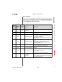
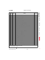
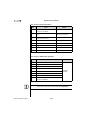
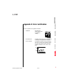
1
Appendix B Error rectification
2
Errors in operation are signalled as follows:
• CDD3000:
Red LED (H1)
flashes (flash code
see Table A.2
“LEDs”)
• DRIVEMANAGER
Possible causes of the error and measures
to remedy it are displayed in a window.
• KEYPAD KP200:
The display is backlit in red and indicates
the error (1) and an error location number
(2). The error location number provides
detailed localization of the cause of the
error.
(2)
VAL
3
4
5
(1)
A
DE
EN
CDD3000 Application Manual
A-17
Appendix B Error rectification
Error response
When an error occurs the servocontroller responds with a specific function sequence. This is allocated to a corresponding response number.
Responseno.
Function
0
Signal error only, no further response (warning).
1
Signal error and disable power stage.
2
Signal error, quick-stop and wait for cancellation of start signal.
3
Signal error, disable power stage and secure against restarting 1).
Signal error, quick-stop, wait for cancellation of start signal and secure
4
against restarting 1).
Signal error, disable power stage and wait for error reset; error reset only
possible by complete cutting of power.
5
1) Only relevant with programmed autostart function.
Table A.1
Error response
LEDs
At the top right of the servocontroller there are three status LEDs colored
red (H1), yellow (H2) and green (H3).
Device status
Red LED (H1)
Power on
❍
❍
●
Servocontroller ready (ENPO set)
❍
●
●
Control enabled
❍
✳
●
✳ (flash code)
❍
●
Warning (in “ready” condition)
●
●
●
Warning (in “control enabled”
condition)
●
✳
●
Error
❍ LED off, ● LED on, ✳ LED flashing
Table A.2
CDD3000 Application Manual
Yellow LED (H2) Green LED (H3)
Meanings of LEDs
A-18
Appendix B Error rectification
Error messages
If an error occurs in operation it is indicated by a flash code from LED H1
(red) on the servocontroller. If a KP200 is connected the KP200 indicates
the error type as an abbreviation. When the DRIVEMANAGER is active the
error is additionally reported in plain text.
Flash
code of
red LED
H1
Display
KEYPAD
1x
Various
messages
0-5
2x
E-OFF
1
3x
Response
Explanation
No.
E-OC
3
Cause/Remedy
1
2
see Table A.2
Undervoltage shut-off
Check power supply. Also occurs briefly in response to
normal power-off.
Current overload shut-off
Short-circuit, ground fault: Check cabling of connections,
check motor coil, check neutral conductor and grounding
(see also section 3, Installation).
Device setup not correct: Check parameters of control loops.
Check ramp setting.
4x
E-OV
3
Voltage overload shut-off
Voltage overload from mains: Check mains voltage. Restart
device.
Voltage overload resulting from feedback from motor
(regenerative operation): Slow down braking ramps. If not
possible, use a braking resistor.
5x
E-OLM
3
Motor protection shut-off
Motor overloaded (after I x t monitoring): Slow down process
cycle rate if possible. Check motor dimensioning.
6x
E-OLI
3
Device protection shut-off
Device overloaded: Check dimensioning. Possibly use a
larger device.
7x
E-OTM
3
Motor PTC correctly connected?:
Motor PTC evaluation correctly set?
Motor temperature too high
Motor overloaded?
Allow motor to cool down. Check dimensioning.
8x
E-OTI
3
Overheating in
servocontroller
Table A.1
Ambient temperature too high: Improve ventilation in switch
cabinet.
Load too high during driving/braking: Check dimensioning.
Possibly use a braking resistor.
3
4
5
A
Error messages/flash code
DE
EN
CDD3000 Application Manual
A-19
Appendix B Error rectification
Bus
DM/KP
Error
location
no.
0
Meaning
Comment
No error
1
E-CPU
Processor defective
1
2
E-OFF
1
Undervoltage in DC link
3
E-OC
19
Max. permissible output current exceeded (software shut-off)
3
E-OC
34
Current overload shut-off of servo resulting from fast Ixt, effective to 5Hz output
frequency
3
E-OC
35
Short-circuit detected during self-test
3
E-OC
41
Max. permissible output current exceeded (hardware shut-off)
4
E-OV
1
Overvoltage in DC link
5
E-OLM
1
Current overload shut-off: IxIxt monitoring of motor, dependent on parameter MOI2T
6
E-OLI
1
Current overload shut-off: Ixt monitoring of servo
7
E-OTM
1
Motor overheating
8
E-OTI
31
Servo heat sink overheating
8
E-OTI
32
Servo interior overheating
9
E-PLS
Plausibility check detected invalid parameter or program sequence
1
10
E-PAR
7
Value range infringement of a parameter setting detected. Parameter ERPAR
contains number of incorrect parameter
1
10
E-PAR
8
After reinitialization of the parameter list in the device startup phase an invalid
parameter value was found. Parameter ERPAR contains the number of this
parameter.
1
10
E-PAR
9
Error initializing a parameter with its permanent memory value. Parameter ERPAR
contains the number of the parameter.
1
10
E-PAR
13
The combination of function selector settings for one of the analog inputs and the
reference selector are mutually contradictory.
1
10
E-PAR
16
Error initializing factors for analog output to digital outputs.
1
10
E-PAR
101
Setting of number of resolver pole pairs not possible
1
11
E-FLT
Global error in floating point calculation
1
12
E-PWR
6
No power stage, or power stage unknown: No valid power stage ID detected
1
12
E-PWR
8
No power stage, or power stage unknown: No valid power stage ID detected
1
13
E-EXT
1
Error request received via digital input with function E-EXT
Note:
1 = If this error is repeated please contact your local Service Partner
2 = See description of field bus (user manual)
Table A.2
CDD3000 Application Manual
Error messages
A-20
Appendix B Error rectification
Bus
DM/KP
Error
location
no.
14
E-USR
1
15
E-OP1
Error in option module at slot 1 (X8)
2
16
E-OP2
Error in option module at slot 2 (X9)
2
11
Meaning
Comment
18
E-SIO
19
E-EEP
SIO watchdog tripped (LustBus)
25
E-HWE
47
Hardware limit switches interchanged
30
E-ENC
1
Encoder wire break detection
30
E-ENC
123
Hiperface: Communication error signalled by encoder
30
E-ENC
124
Hiperface: Communication error signalled by dSMC
30
E-ENC
125
Hiperface: Unknown encoder type
30
E-ENC
126
Hiperface: Error signalled by encoder (but communication is OK)
30
E-ENC
127
Hiperface: Communication parameters not found
31
E-TIM
32
E-FLW
34
E-VEC
35
E-BRK
1
36
E-POS
210
Pos. hardware limit switch approached
36
E-POS
211
Neg. hardware limit switch approached
36
E-POS
212
Pos. software limit switch approached
36
E-POS
213
Neg. software limit switch approached
36
E-POS
214
Positioning job with no defined reference point
36
E-POS
215
Error accessing optional hardware
36
E-POS
216
Selected program not available
36
E-POS
217
Jump to non-existent record number
36
E-POS
218
Called subroutine not available
36
E-POS
219
Position outside positioning range
36
E-POS
220
Division by zero
36
E-POS
221
Max. subroutine nesting depth exceeded
36
E-POS
223
Destination position not reached
36
E-POS
224
No feed hold (only positioning commands)
Error accessing EEPROM
1
Runtime monitor error
1
1
Error executing a customer-specific software function
2
3
1
Tracking error
Initialization error
1
Monitoring unit for brake output (OSD03) signals error
4
5
A
Note:
1 = If this error is repeated please contact your local Service Partner
2 = See description of field bus (user manual)
Table A.2
CDD3000 Application Manual
Error messages
DE
EN
A-21
Appendix B Error rectification
Bus
DM/KP
Error
location
no.
36
E-POS
225
Selection (Auto/Referencing/Jog) not permitted
36
E-POS
226
ProgPos: Index overflow in indexed addressing, TabPos: table index faulty
(1<=Index<=31)
36
E-POS
233
Error writing a parameter in sequence program
36
E-POS
234
Error executing a positioning command with positioning travel by Touchprobe
36
E-POS
235
Impermissible command in this status
36
E-POS
236
Hardware limit switches interchanged
37
E-FLH
38
E-HW
45
Hardware limit switch left (all control modes)
38
E-HW
46
Hardware limit switch right (all control modes)
39
E-HWE
47
Hardware limit switches interchanged (all control modes)
40
E-WRN
59
Torque limit (TCMMX) automatically limited
40
E-WRN
60
Cycle time of status report via field bus too short
40
E-WRN
61
Position reference / travel scaling outside value range
40
E-WRN
62
Speed limit (SCSMX) automatically limited
40
E-WRN
63
Position reference / velocity or acceleration scaling outside value range
Meaning
Comment
Error in data flash memory
1
Note:
1 = If this error is repeated please contact your local Service Partner
2 = See description of field bus (user manual)
Table A.2
Service Hotline
Error messages
If you need further assistance, our specialists at the LUST Service Center
will be glad to help.
You can reach us:
CDD3000 Application Manual
Mon.-Thur.: 8 a.m. - 5 p.m.
Tel. +49-6441/966-136, Fax -211
Fri.:
8 a.m. - 4 p.m.
Tel. +49-6441/966-136, Fax -211
E-mail:
[email protected]
A-22
Appendix B Error rectification
Resetting errors
(after eliminating the cause)
Resetting errors with response number 1 to 4:
• In control via terminals:
rising edge at input ENPO
(attention: control is shut off!)
or:
1
with input Ixxx, to which the function FIxxx = RSERR (Reset Error)
is assigned.
• In control via KEYPAD: press
Starting the drive after an error
stop/return key on KEYPAD for
approx. 3 seconds
• In control via DRIVEMANAGER:
click on “Reset error” button.
• In control via field bus:
set “Reset error” bit in bus control
word.
• Cancel start signal and reapply it.
3
• With programmed auto-start function:
−
−
2
In error responses 1 and 2 the drive automatically restarts when
the error is reset.
In error responses 3 and 4 the drive does not restart until the
start signal has been withdrawn and re-sent.
4
Resetting errors with response number 5:
Errors with response number 5 are serious device errors. They can only
be reset by switching all supply voltages (mains, possibly 24V) off and
back on again.
Errors in power switching
Error
Power on. Servocontroller
shows no response (LEDs
off).
Cause
If switching is too frequent,
the device protects itself by
means of high-resistance
isolation from the system.
Remedy
5
After a rest phase of a few
minutes the device is ready
to start once again.
A
DE
EN
CDD3000 Application Manual
A-23
Appendix B Error rectification
User errors in KEYPAD operation
Error
Cause
Remedy
ATT1
Parameter cannot be changed at current
user level or is not editable.
Select user level 1-MODE higher.
ATT2
Motor must not be controlled via the CTRL
menu.
Cancel start signal from a
different control location.
ATT3
Motor must not be controlled via the CTRL
menu because of error state.
Reset error.
ATT4
New parameter value impermissible
Change value.
ATT5
New parameter value too high
Reduce value.
ATT6
New parameter value too low
Increase value.
ATT7
Card must not be read in current state.
Reset start signal.
ERROR
Invalid password
Enter correct password.
Table A.3
KEYPAD user error
User errors in SMARTCARD operation
Error
ERR91
SMARTCARD write-protected
ERR92
Error in plausibility check
ERR93
SMARTCARD not readable, wrong servocontroller type
ERR94
SMARTCARD not readable, parameter not compatible
ERR96
Connection to SMARTCARD broken
ERR97
SMARTCARD DATA invalid (checksum)
ERR98
Insufficient memory on SMARTCARD
ERR99
Selected area not present on SMARTCARD, no parameters
transferred to SMARTCARD
Table A.4
Note:
CDD3000 Application Manual
Meaning
Remedy
Use different
SMARTCARD
SMARTCARDerror
KeyPad user errors can be reset with start/enter.
SMARTCARD user errors can be reset with stop/return.
A-24