1
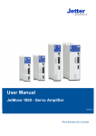
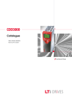
EN
EN
CDF3000
Operation Manual
Positioning Drive
Rated current 8 A
Mains 24 ... 48 V DC
Positioning Drive
Rated current 8 A
Mains 24 ... 48 V DC
CDF3000 Operation Manual
D
ID no.: 1040.20B.0-00 • 11/2005
Valid from software version CDF V1.0
We reserve the right to make technical changes.
Overview of documentation
Document
Order designation
Purpose
Operation Manual
CDF3000
1040.20B.x-xx
Installation and initial commissioning
Application Manual
CDE/CDB/CDF3000
1001.22B.x-xx
Project planning and function description
Communications
Manual CANopen
Project planning and function description
Communications
Manual PROFIBUSDP
Project planning and function description
Table of contents
1
Safety
1
2
Mechanical installation
2
3
Electrical Installation
3
4
Commissioning
4
5
Diagnosis/Troubleshooting
5
Appendix :
CDF3000 Operation Manual
Technical data, ambient conditions
UL approval
A
DE
EN
FR
IT
Pictograms
Attention! Misoperation may damage the drive or
cause it to malfunction.
Danger from electrical tension! Improper conduct
may endanger human life.
Danger from rotating parts! Drive may start up
automatically.
Note: Useful information
CDF3000 Operation Manual
Table of contents
CDF3000 Operation Manual
1
Safety
1.1
For your safety ........................................................1-1
1.2
Intended use ............................................................1-3
1.3
Responsibility ..........................................................1-3
2
Mechanical installation
2.1
Notes for operation .................................................2-1
2.2
Mounting, devices end-to-end ...............................2-2
3
Electrical Installation
3.1
Connections .............................................................3-2
3.2
Position plan ............................................................3-3
3.3
3.3.1
Connecting the power packs ..................................3-4
Cable cross-section for X1 and X3 .......................3-6
3.4
Motor connection ....................................................3-7
3.5
3.5.1
3.5.2
3.5.3
3.5.4
Encoder connection for Lust motors ......................3-8
Specification of interface X6 ................................3-8
Connection of a second encoder to X6 ...............3-10
Motor temperature monitoring ...........................3-10
Project planning notes for encoder connection ...3-11
3.6
Serial interface (SIO) .............................................3-12
3.7
CANopen interface X5 .............................................3-14
3.8
Multi-axis operation ..............................................3-15
3.9
Braking resistor (RB) ............................................3-17
3.10
3.10.1
Control connections ..............................................3-18
Specification of control connections ...................3-19
DE
EN
FR
IT
ES
FR
3.11
3.11.1
3.11.2
CDF3000 Operation Manual
3.11.3
3.11.4
Safe Standstill ....................................................... 3-22
Function description .......................................... 3-22
Additional safety instructions for the
“Safe Standstill” function .................................. 3-23
Wiring and commissioning ................................. 3-24
Testing .............................................................. 3-26
4
Commissioning
4.1
Choice of commissioning ....................................... 4-1
4.2
4.2.1
4.2.2
Serial commissioning .............................................4-2
Serial commissioning with KEYPAD ....................... 4-2
Serial commissioning with DRIVEMANAGER ............ 4-4
4.3
4.3.1
4.3.2
4.3.3
4.3.4
Initial commissioning .............................................4-5
Preset solutions .................................................. 4-7
Setting the motor and encoder ............................. 4-9
Making basic settings ........................................ 4-13
Saving the settings ............................................ 4-14
4.4
Test run .................................................................4-15
4.5
Operation with KEYPAD KP200XL ..........................4-19
4.6
Operation with DRIVEMANAGER ..............................4-22
5
Diagnosis/Troubleshooting
5.1
LEDs ........................................................................ 5-1
5.2
Error messages ....................................................... 5-2
5.3
User errors in KEYPAD operation .............................5-4
5.4
User errors in SMARTCARD operation ....................... 5-4
5.5
Reset ....................................................................... 5-5
A
Appendix
A.1
Technical data ........................................................ A-2
A.2
Ambient conditions ................................................ A-3
A.3
UL approbation ....................................................... A-4
B
Index
DE
EN
FR
IT
ES
FR
CDF3000 Operation Manual
CDF3000 Operation Manual
1
1 Safety
1.1
For your safety
The instructions set out below should be read through prior to initial
commissioning in order to prevent injury and/or damage to property. The
safety instructions must be followed at all times.
Read the Operation Manual first!
• Follow the safety instructions!
2
3
Electric drives are
dangerous:
• Rotating parts
4
• Hot surfaces
• Electrical tension
Protection against magnetic and/or electromagnetic
fields during installation and operation.
• Persons fitted with heart pacemakers, metallic implants
and hearing aids etc. must not be allowed access to the
following areas:
−
−
Note:
CDF3000 Operation Manual
Areas where drive systems are installed, repaired
and operated.
Areas where motors are installed, repaired and
operated. Motors with permanent magnets pose a
particular hazard.
5
A
If it is necessary to accss such areas, suitability
to do so must be determined beforehand by a
doctor.
1-1
DE
EN
FR
IT
ES
FR
1 Safety
Your qualification:
• In order to prevent personal injury or damage to
property, only personnel with electrical engineering
qualifications may work on the device.
• The said qualified personnel must be familiar with the
contents of the Operation Manual (cf. IEC364,
DIN VDE0100).
• Awareness of national accident prevention regulations
(e.g. VBG 4 in Germany)
During installation observe the following instructions:
• Always comply with the connection conditions and
technical specifications.
• Comply with the standards for electrical installations,
such as regarding cable cross-section, PE conductor
and earth connections.
•
Do not touch electronic components and contacts
(electrostatic discharge may destroy components).
Pictograms used
The safety instructions detail the following hazard classes.
The hazard class defines the risk posed by failing to comply with the
safety notice.
Warning
symbols
General explanation
Hazard class to ANSI Z 535
Attention! Misoperation may damage the drive or
cause it to malfunction.
Injury or damage to property
may occur.
Danger from electrical tension!
conduct may endanger human life.
Improper
Death or serious injury will
occur.
Danger from rotating parts! Drive may start up
automatically.
Death or serious injury will
occur.
CDF3000 Operation Manual
1-2
1 Safety
1.2
Intended use
Drive controllers are components that are intended for installation in
electrical systems or machines.
The drive controllers may not be commissioned (i.e. it may not be put to
their intended use) until it has been established that the machine
complies with the provisions of EC Directive 98/37/EC (Machinery
Directive); EN 60204 is to be observed.
1
Commissioning (i.e. putting the device to its intended use) is only
permitted in compliance with the EMC Directive (89/336/EEC).
The CDF3000 conforms to the EMC Directive 89/336/EEC.
2
The harmonized standards EN 61800-3 and EN 61800-5-1 are applicable
to the drive controllers.
If the drive controller is used for special applications (e.g. in areas
subject to explosion hazard), the required standards and regulations
(e.g. EN 50014, “General provisions” and EN 50018 “Pressurized
enclosure”) must always be observed.
3
Repairs may only be carried out by authorized repair workshops.
Unauthorized opening and incorrect intervention could lead to death,
physical injury or damage to property. The warranty provided by LUST
would thereby be rendered void.
1.3
Responsibility
Electronic devices are fundamentally not fail-safe. The company setting
up and/or operating the machine or plant is itself responsible for ensuring
that the drive is rendered safe if the device fails.
EN 60204-1/DIN VDE 0113 “Safety of machines”, in the section on
“Electrical equipment of machines”, stipulates safety requirements for
electrical controls. They are intended to protect personnel and machinery,
and to maintain the function capability of the machine or plant concerned,
and must be observed.
An emergency off system does not necessarily have to cut the power
supply to the drive. To protect against danger, it may be more beneficial to
maintain individual drives in operation or to initiate specific safety
sequences. Execution of the emergency off measure is assessed by
means of a risk analysis of the machine or plant, including the electrical
equipment to DIN EN 1050, and is determined with selection of the circuit
category in accordance with DIN EN 954-1 “Safety of machines – Safetyrelated parts of controls”.
CDF3000 Operation Manual
1-3
4
5
A
DE
EN
FR
IT
ES
FR
1 Safety
CDF3000 Operation Manual
1-4
1
2 Mechanical installation
2
2.1
2.1
Notes for operation .................................................2-1
2.2
Mounting, devices end-to-end ...............................2-2
3
Notes for
operation
Please ensure that ...
•
•
•
•
no damp enters the device
no aggressive or conductive substances are in the immediate vicinity
no drill chippings, screws or foreign bodies drop into the device
the vent openings are not covered over.
4
The device may otherwise be damaged.
5
A
CDF3000 Operation Manual
2-1
DE
EN
FR
IT
ES
FR
2 Mechanical installation
2.2
Mounting,
devices end-toend
Important: In accordance with EN 61800-5-1, the device is suitable only
for cabinet installation.
Step
Action
Comment
1
Mark out the position of the tapped holes
on the backing plate.
Cut a tap for each fixing screw in the
backing plate.
Dimensional drawings/hole
spacing see Table 2.1.
The tapping area will provide
you with good, full-area contact.
2
Pay attention to the mounting
Mount the positioning drive vertically on clearances!
The contact surface must be
the backing plate.
metallically bright.
3
Mount the other components, such as
the braking resistor etc., on the backing
plate.
4
Continue with the electrical installation in
section 3.
G
F
E
F
Figure 2.1 Mounting clearances (see Table 2.1)
CDF3000 Operation Manual
2-2
2 Mechanical installation
CDF30.008
Weight [kg]
W (width)
H (height)
D (depth)
0,8
55
143
121
A
C
C1
D
E
F
G
H1
27,5
157
5,2
4,8
15
100
> 150
167,5
1
2
T
3
B
4
C
H
H1
5
D
C1
A
1) For flat mounting
Table 2.1
Dimensional drawings for vertical mounting (dimensions in mm)
A
Note the following points:
• Air must be able to flow unhindered through the device.
• For mounting in switch cabinets with convection (= heat loss is
discharged to the outside via the cabinet walls) an internal air
circulation fan must always be fitted.
• The backing plate must be well earthed.
CDF3000 Operation Manual
2-3
DE
EN
FR
IT
ES
FR
2 Mechanical installation
CDF3000 Operation Manual
2-4
1
3 Electrical Installation
Connections .............................................................3-2
3.2
Position plan ............................................................3-3
3.3
3.3.1
Connecting the power packs ..................................3-4
Cable cross-section for X1 and X3 .......................3-6
3.4
Motor connection ....................................................3-7
3
3.5
3.5.1
3.5.2
3.5.3
3.5.4
Encoder connection for Lust motors ......................3-8
Specification of interface X6 ................................3-8
Connection of a second encoder to X6 ...............3-10
Motor temperature monitoring ...........................3-10
Project planning notes for encoder connection ...3-11
4
3.6
Serial interface (SIO) .............................................3-12
3.7
CANopen interface X5 .............................................3-14
3.8
Multi-axis operation ..............................................3-15
3.9
Braking resistor (RB) ............................................3-17
3.10
3.10.1
Control connections ..............................................3-18
Specification of control connections ...................3-19
3.11
3.11.1
3.11.2
Safe Standstill .......................................................3-22
Function description ..........................................3-22
Additional safety instructions for the
“Safe Standstill” function ...................................3-23
Wiring and commissioning .................................3-24
Testing ..............................................................3-26
3.11.3
3.11.4
Important: Installation must only be carried out by qualified electricians
who have undergone instruction in the necessary accident
prevention measures.
CDF3000 Operation Manual
2
3.1
3-1
5
A
DE
EN
FR
IT
ES
FR
3 Electrical Installation
Connections
X5
BCD
CAN_HIGH
CAN_LOW
CAN_GND
CAN_+24V
CAN_Sync_H
CAN_Sync_L
CDF3000
1
EF 2
S1
56
CAN master
X4
34
7
2
3
9
8
4
RS232
890A
3
COM1 / COM2
7
3.1
SSI encoder
X2
Open-loop control
Analog setpoint 1
Analog setpoint 2
+24V against I/O GND
ver
10 OSD00
20
OSD05
19
Digital0
KRY2-CDF-KSxxx
X3
16 ISDSH
18
RSH
17
Safe Standstill request
Safe Standstill checkback
X1
GND
+
4
5
+24V
* with power drivers 2 A
11
2
1
Power driver 0,5 A
U
U
V
V
W
W
PE
Motor
3
KM2-KSxxx
3
I/O GND
for control section
8
incl. temperature sensor
8
Resol-
12 ENPO
13
ISD00
14 ISD01
15
ISD02
Safety circuit
Power pack 24V DC/ 0,9 A*
X6
7
ISA00+
6
ISA009
ISA01+
8
ISA01-
Braking resistor
BR+ BR+
BR- BRPE PE
PE PE
L+ L+
L- L-
OSD03
OSD04
(*)
Power driver 0,5 A
Power pack 24/48V DC/10 A*
for
power section
+
Brake+
Brake-
* at overload up to 20 A/30s
Figure 3.1 Terminal diagram, CDF3000 (overview)
* Power pack must be protected against voltage overload in regenerative operation (e.g. by
a protective diode).
Key
CDF3000 Operation Manual
Explanation
Continue
X1
Power connection (6-pole plug-in terminal)
Page 3-4
X2
Control connection (2 x 10-pole plug-in terminal)
Page 3-18
X3
Motor connection (4-pole plug-in terminal)
Page 3-7
X4
RS232 connection, for operation with NOTEBOOK/DRIVEMANAGER
see section 4.5/4.6 (9-pole Sub-D socket)
Page 3-12
3-2
3 Electrical Installation
Key
Explanation
X5
CANopen interface with DS402 profile (9-pole Sub-D pins)
S1
Rotary code switch, CAN address
X6
Resolver/ SSI encoder connection (15-pole HD Sub-D socket)
Continue
Page 3-14
Page 3-8
1
PE connection
Important: Please be sure to refer to section 3.3
“Connecting the power packs”.
Page 3-4
2
Table 3.1
3.2
Key to CDF3000 terminal diagram
Position plan
3
X6
X3
X5
X4
4
5
A
S1
X2
X1
Figure 3.2 CDF3000 position plan
CDF3000 Operation Manual
3-3
DE
EN
FR
IT
ES
FR
3 Electrical Installation
3.3
Connecting the
power packs
The positioning drive may only be connected to power packs (stabilized
and smoothed) conforming to the requirements of a functional extra-low
voltage with safe isolation to EN 50178.
S1
DC system (PELV)
24/48 V =
X2
AC system
230 V ~
X2
AC system
230 V ~
X1
X1
L+
LPE
Safe isolation
Safe isolation
5
4
S1
X2
X2
X1
X1
Power pack 48 V DC
for power section
+
L1
Power pack
24 V DC for
power section
L+
LPE
5
4
+
-
N
-
PE
L1
N
PE
Figure 3.3 Connections of the DC network
Note:
Power side 24/48 V DC: Each device must be provided with
its own dedicated maximum fuse protection of 16 AgG!
Power the control units and power packs from their own
dedicated power supply units!
CDF3000 Operation Manual
3-4
3 Electrical Installation
Note the following points:
• The power packs must have energy recovery capability (e.g. in
regenerative operation). The threshold for use of the braking
chopper is 58 V DC.
1
• In view of the high dynamics of the DC link, the power supply unit of
the power pack (supplied of X1) should be used only for operation
of the CDF3000 (no other consumers permitted).
• Appropriate cable protection must be provided within the DC
network. The cables must be protected by suitable fuses.
2
• The PE conductor must be laid out in star configuration to conform
to the EMC standards.
• The motor cable, mains lead and control cable must be laid
separately from each other.
• Avoid loops, and lay cable over short distances.
• The (–) poles of the power packs should be earthed at the feed-in
point, as shown in figure 3.3.
Important: +24 V Supply voltage (X2)
To protect the device against fire, a 7 A rating fuse is
integrated into the voltage supply cable inside the device. The
shut-off capacity of the fuse is limited to 30 A. If you use a
voltage source with a higher maximum current, fit a 6 A backup fuse with a switching capacity appropriate to the maximum
current of the power supply unit. Always ensure the cable is
protected!
3
4
5
A
CDF3000 Operation Manual
3-5
DE
EN
FR
IT
ES
FR
3 Electrical Installation
3.3.1 Cable crosssection for X1
and X3
Positioning drive
Device connected load [kVA]
Cable cross-section [mm²]
CDF30.008
0,55
1.5 ... 2.5
Table 3.2
Cable cross-section (ensure compliance with VDE0298)
The CDF3000 has no precharging circuit. It therefore does not limit the
charging current when the supply voltage is switched on. To utilize the
current limitation of the power supply unit, the power should be switched
upstream of the power supply unit (see Figure 3.4).
Incorrect:
Correct:
L1
L1
+
L+
N
PE
-
L-
PE
PE
Figure 3.4 Connection of supply voltage
CDF3000 Operation Manual
+
L+
-
L-
N
3-6
PE
3 Electrical Installation
3.4
Motor
connection
Info: The CDF3000
positioning drives are
short-circuit-proof
at
the terminals during
operation. In the event
of a short-circuit in the
motor cable, the power
stage is disabled and
an error message is
delivered.
LUST synchronous servomotors are optimally attuned to the CDF3000
positioning drive. Prefabricated motor and encoder cables are also
available. For more information on motors of the LSH series and on
accessories refer to the “Servomotors Order Catalogue ID no.
0814.05B.x-xx”.
Step
Action
1
Comment
Three motors are available
(LST-037, LSH-050, LSH074).
1
Select your desired synchronous motor.
2
Wire the motor phases U, V, W by way of
Use the prefabricated motor
a screened cable and earth the motor to
cable of type KM2-KSxxx
X3/PE.
3
The connection of the PTC or KTY
temperature sensor is integrated in the
encoder cable (see section 3.x).
2
Use the prefabricated encoder
cables:
KRY2-CDF-KSxxx (resolver)
3
W
V
U
PE
U
U
V
W
V
W
M
3~
PE
X3
KM2-KSxxx
4
Figure 3.5 Connection of motor
X3
CDF3000 Operation Manual
Important: Motor phases U,V and W must never be reversed! If the
motor phases are reversed the positioning drive has no
control over the motor. The motor may buck or accelerate in
an uncontrolled manner (“race”).
5
Important: The device is then not earth fault-proof at the motor
terminals!
A
3-7
DE
EN
FR
IT
ES
FR
3 Electrical Installation
3.5
Encoder
connection for
Lust motors
Step
Action
Comment
1
Select the correct encoder type
2
Wire the encoder connection with a
screened wire
Use the prefabricated encoder
cables:
KRY2-CDF-KSxxx (resolver)
Matching motor - encoder cable - servocontroller connection
Compare the name plates of the components. Be sure to use the right
components!
Earth the motor cable screen on the backing plate as close as possible to
the CDF3000.
KRY2-CDF-KS xxx
X3
X6
The encoder cable
must not be split, for
example to route the
signals via terminals in
the switch cabinet.
Ensure that the knurled
screws on the D-sub
connector plug are
secured!
KM2-KS-xxx
Resolver
Motor LSH/LST
Figure 3.6 Matching motor/encoder cable
3.5.1 Specification of
interface X6
The electrical specification of the interface is given in Table 3.3, the
terminal assignment in Table 3.4.
Resolver
Connection
Miniature D-SUB 15-pole socket (high-density)
Interface
-
RS422 (differential)
Wave terminating resistance
-
DATA: 120 Ω (internal)
CLK: No termination required
Max. signal frequency fLimit
Table 3.3
CDF3000 Operation Manual
SSI encoder
500 kHz
Specification of encoder interface X6
3-8
3 Electrical Installation
Resolver
SSI encoder
Voltage supply
-
+ 5.2 V ±5%, max. 150 mA
Not isolated from the power
potential (+48 V)
Sampling rate
8 kHz
4 kHz
Interface log
-
SSI (Graycode)
Lines per revolution /
resolution
-
13 bit (single-turn)
25 bit (multi-turn)
Max. cable length
20 m (longer lengths on request)
Table 3.3
1
2
Specification of encoder interface X6
The cable type for SSI encoders should be selected according to the
encoder manufacturer's specification, bearing in mind the following:
• Use only screened cables. Apply the screening on both sides.
• Connect the differential track signals A, B or CLK, DATA to each
other via twisted cable strands.
3
• Do not separate the encoder cable, for example to route the signals
via terminals in the switch cabinet.
15 14 13 12 11
5 4 3 2 1
Resolver/
SSI
10 9 8 7 6
X6
X6 pin
Resolver function
SSI function
1
Sine- (S4)
-
2
Sine+ (S2)
-
3
-
+5V (150 mA)
+ 5 V (150 mA)
4
-
DATA+
A+
5
-
DATA-
A-
6
Cosine- (S3)
-
7
REF- (R2) (excitation-)
-
8
-
GND
9
PTC- (KTY / Klixon)
PTC- (KTY / Klixon)
PTC+ (KTY / Klixon)
PTC+ (KTY / Klixon)
11
Cosine+ (S1)
-
12
REF+ (R1) (excitation+ [8 kHz,
approx. 7 V AC])
-
13
n.c.
-
14
-
CLK+
B+
15
-
CLK-
B-
Assignment of encoder interface X6
3-9
4
5
GND
10
Table 3.4
CDF3000 Operation Manual
TTL function
A
DE
EN
FR
IT
ES
FR
3 Electrical Installation
3.5.2 Connection of a
second encoder
to X6
Parallel to the resolver connection (see section 3.5), an SSI encoder can
be evaluated at X6.
When using simultaneously, as described in Figure 3.7 the
SSI encoder should be used only for position control. The motor
commutation and secondary speed control is then performed by way of
the resolver.
DRIVE
position
speed
X6
M
Resolver
SSI
Figure 3.7 Drive with two measuring systems
3.5.3 Motor
temperature
monitoring
For thermal monitoring of the motor coil, a thermistor (PTC) can be
connected to X6/9 and 10 over the encoder cable. The type used must be
set during commissioning in parameter 330-MOPTC (factory default
setting is “off”).
Sensor
No PTC
used
Standard
PTC
Linear voltage
evaluation
TSS,
Thermal circuitbreaker
–
PTC to
DIN 44082
KTY84-130,
(tolerance band
yellow)*
Klixon
Parameter
330-MOPTC =
OFF
DIN
KTY
TSS
Measurement
voltage UMAX
–
Tech. data
Usable type
Error message
5V
–
E-OTM
* In KTX evaluation the cut-out temperature can be selected within limits (150 °C ... 250 °C)
Table 3.5
Motor temperature monitoring specification
Important: When using third-party motors, it must be ensured that the
motor temperature sensor used provides adequate insulation
to the motor coil.
CDF3000 Operation Manual
3-10
3 Electrical Installation
3.5.4 Project
planning notes
for encoder
connection
The maximum number of lines per revolution of the encoder can be
calculated by the following formula.
LRmax =
60 . f limit
LR max =
n max
Maximum number of lines of encoder in
pulses per rev.
nmax =
Maximum speed of motor in rpm
flimit=
Maximum input signal frequency of
interface
Example of nmax = 6000 1/min, fGrenz = 150 kHz:
Calculated:
Selected:
Minimum motor speed
LR max =
60 . 150.000
= 1500
6000
1
2
pulses/rev.
An encoder with 1024 pulses per rev.
3
Formula for calculating the minimum displayable motor speed nmin,
depending on the lines per revolution of the encoder:
n min =
Note:
3000 . 1
min
LR
LR =
Number of lines of encoder in pulses per rev.
nmin =
Minimum speed of motor in rpm
A speed <nmin cannot be measured. In this range the actual
speed is constant = 0 rpm. In the range 0 < n < nmin the
gain of the speed controller is reduced.
4
5
A
CDF3000 Operation Manual
3-11
DE
EN
FR
IT
ES
FR
3 Electrical Installation
3.6
Serial interface
(SIO)
The serial interface (SIO, X4) is used to connect a KEYPAD with a
SMARTCARD or a notebook on which the DRIVEMANAGER PC tool is
installed. This enables the CDF3000's parameters to be set.
ER
NAG
EMA
RIV
T D
LUS
C:\Pro
gramm
e\L
Dri
\LUST
GmbH en:
nik
ung
bstech llte Lös
gang
leich
Antrie eingeste
ust
Vor
Eil-/Sch
veM
ana
ger\us
Grun
ungen..
deinstell
e...
X
rt >>
Erweite
rieb,
Taktant
.
..
Erstinbe
trieb
nahme.
Hilfe
arnu
Fehler/W
Istwerte
X4
Eins
Important: The RS232
interface may only be
used for service and
commissioning. Control
via this interface is not
permitted.
RS232
ng ...
Abbbre
chen
...
in
tellung
Date
i spe
ichern
3mm
ax.
RS232
CCD-SUB90X
Parameter
VAL
Hz
start
enter
stop
return
Figure 3.8 Terminal X4
Please use the prefabricated RS232 cable CCD-SUB 90X (maximum
length 3 m) to connect the positioning drive.
Pin assignment X4
Pin no.
9 8 7 6
SIO
5 4 3 2 1
X4
1
+15 V DC for operation panel KP200XL
2
TxD, send data
3
RxD, receive data
4
Do not use
5
GND for +15 V DC of operation panel KP200XL
6
Do not use
7
Do not use
8
Do not use
9
Do not use
Table 3.6
CDF3000 Operation Manual
Function
Pin assignment of serial interface X4
3-12
3 Electrical Installation
Important: The RS232 interface is connected to the potential of the (–)
pole of the power electronics. Possible differences in potential
between the earth of the (–) pole and of the notebook may
cause a PE loop via the screen and the signal wires of the
interface cable and the screen earth on the notebook. This
may destroy the RS232, the notebook and the CDF3000! We
therefore recommend using an opto-isolator in the interface
cable.
1
2
ER
NAG
EMA
RIV
T D
LUS
CDF3000
C:\P
rogram
me\Lu
st Ant
T Dri
bH\LUS
ik Gm ngen:
stechn lte Lösu gang
rieb
stel
inge
Schleich
Vore
eb, Eil-/
Grun
Erstinbet
riebn
24/48 V DC
+
-
-
ngen
ana
ger\us
e...
Erwe
itert
X
>>
...
3
Hilfe
rte ...
Einstellu
+
deinstellu
ahme...
Fehler/W
Istwe
veM
Taktantri
ng in
Date
i spei
cher
arnu
ng ...
Abbbrec
hen
n
RS232 (X4)
2
RS232
PE
4
CDF3000
±
Notebook
PE
Figure 3.9 Serial interface connection
5
A
CDF3000 Operation Manual
3-13
DE
EN
FR
IT
ES
FR
3 Electrical Installation
3.7
CANopen
interface X5
The CANopen interface is built into the positioning drive. The connection is
made via connector X5. The power supply to the isolated connection is
provided by the customer.
Connection
Miniature D-Sub 9-pin plug
120 Ω (internal)
to be wired by customer via jumper
(pin 1-2)
Wave terminating resistance
- Bus termination Max. input frequency
1 MHz
+ 24 V +10%
(floating to the drive controller)
Ext. voltage supply
Table 3.7
CANopen interface connection
Assignment of connection X5:
Pin
9 8 7 6
CANopen
5 4 3 2 1
X5
Function
1
Wave terminating resistance 120 Ω internal for CAN
by jumper between pins 1 and 2
2
CAN_LOW
3
CAN_GND
4
CAN-SYNC_LOW This pin can be optionally switched by the microcontroller
as an input or output.
5
Wave terminating resistance 120 Ω internal for CAN-SYNC
by jumper between pins 4 and 5
6
CAN_GND
7
CAN_HIGH
8
CAN-SYNC_HIGH This pin can be optionally switched by the microcontroller
as an input or output.
9
CAN_+24 V (24 V ±10%)
Table 3.8
Pin assignment, connection X5
The CAN bus node address is set via the coding switch S1.
CDF3000 Operation Manual
3-14
3 Electrical Installation
3.8
Multi-axis
operation
The positioning drives running in regenerative operation (braking) in a
multi-axis network feed power into the network which is consumed by the
motor-driven positioning drives.
Networked operation of several positioning drives minimizes the power
consumption from the mains and external braking resistors can be
eliminated where appropriate.
1
2
3
4
5
A
CDF3000 Operation Manual
3-15
DE
EN
FR
IT
ES
FR
-
CDF3000 Operation Manual
+
+
Figure 3.10 CDF3000 network diagram
3-16
Power pack
24/48V DC for
power section
U
V
W
PE
BR+
BR-
PE
L+
L-
ISDSH
RSH
RSH
GND
OSD04
+24V
GND
ENPO
ISD00
ISD01
ISD02
OSD00
OSD05
OSD05
8
Brake
Braking resistor
4
13
14
15
10
20
19
16
18
17
3
1
5
12
9
2
3
7
1
Resolver
Motor
LSH
CAN master
X6
X3
X1
X2
U
V
W
PE
BR+
BR-
PE
L+
L-
ISDSH
RSH
RSH
GND
OSD04
+24V
GND
ENPO
ISD00
ISD01
ISD02
OSD00
OSD05
OSD05
CAN_LOW
CAN_GND
CAN_+24V
CAN_HIGH
X5
CDF3000
8
Brake
Braking resistor
19
16
18
17
3
1
5
4
12
13
14
15
10
20
9
2
3
7
1
Resolver
Motor
LSH
GND CNC
X6
X3
X1
X2
CAN_LOW
CAN_GND
CAN_+24V
CAN_HIGH
X5
CDF3000
Power pack
24V DC for
control section
-
X6
X3
X1
X2
U
V
W
PE
BR+
BR-
PE
L+
L-
ISDSH
RSH
RSH
GND
OSD04
+24V
GND
ENPO
ISD00
ISD01
ISD02
OSD00
OSD05
OSD05
CAN_HIGH
CAN_LOW
CAN_GND
CAN_+24V
X5
CDF3000
8
Brake
Braking resistor
12
13
14
15
10
20
19
16
18
17
3
1
5
4
9
2
3
7
1
Resolver
Motor
LSH
3 Electrical Installation
Safe Standstill
Ready
GND CNC
GND CNC
3 Electrical Installation
3.9
Braking resistor
(RB)
Important: Braking the drive is important to the safety of the
machine or system!
Commissioning should include a test for safe functioning of
the braking system! Incorrect dimensioning (overload) could
lead to destruction of the braking resistor or the braking
electronics, and damage to the machine or system. Overload
(failure of the braking device) can also lead to serious or fatal
physical injury to human beings, for example in lifting
applications!
In regenerative operation, e.g. braking the drive, the motor feeds energy
back into the positioning drive. This increases the voltage in the DC-link. If
the voltage exceeds a threshold value, the internal braking transistor is
activated and the regenerated power is converted into heat by way of a
braking resistor.
1
2
3
The switching transistor is installed as standard. The design of the
external braking resistor depends on a number of drive factors: for
example the load to be moved, the required dynamics of the drive or the
braking and cycle duration.
4
L+
GND
PE
The RB+ and RBterminals are not shortcircuit and overload proof.
PE
RB+
RB
RB-
5
X1
Figure 3.11 Braking resistor connection
Note the following points:
• The design of the braking resistor must be clarified at the project
planning stage.
A
• For details of the permissible minimum ohmic resistance of an
externally installed braking resistor for the individual positioning
drives refer to Appendix A.2.
For further information please consult your project engineer.
CDF3000 Operation Manual
3-17
DE
EN
FR
IT
ES
FR
3 Electrical Installation
Important: The braking resistor should be mounted such that in the
event of failure of the chopper transistor (e.g. if it shorts) no
fire risk is posed by the braking resistor and measures are
put in place to cut power to the resistor.
3.10 Control
connections
Step
Action
Comment
1
Check whether you already have a
SMARTCARD or a DRIVEMANAGER data
set with a complete device setup, i.e.
the drive has already been planned as
required.
2
If this is the case, a special control
terminal assignment applies. Please
contact your project engineer to obtain
the terminal assignment!
Bulk customers
For details of how to load the data
set into the positioning drive refer
to section 4.2.
3
Choose a terminal assignment.
Initial commissioning
There are various preset solutions
available to make it easier to
commission the device.
4
Wire the control terminals with
screened cables.
The only essential signals are the
ENPO and ISDSH signals and a start
signal (for control via terminal).
Earth the cable screens over a wide
area at both ends.
Cable cross-section maximum
1.5 mm² or two strands per
terminal at 0.5 mm²
5
Keep all contacts open
(inputs inactive).
6
Check all connections again!
Continue with commissioning in
section 4.
Note the following points:
• Always wire the control terminals with screened cables.
• Lay the control cables separately from the mains lead and motor
cable.
• The CDF3000 Application Manual presents more preset drive
solutions.
• A cable type with double copper braiding with 60 – 70% coverage
must be used for all screen connections.
CDF3000 Operation Manual
3-18
3 Electrical Installation
3.10.1 Specification of
control
connections
Control terminal X2 is located on the underside of the device.
Des.
Terminal
X2
Specification
floating
1
S1
Analog inputs differential
X2
20
ISA00+
ISA00-
7
6
ISA01+
ISA01-
9
8
X1
10
UIN = ± 10 V DC
RIN=101 kΩ
Resolution 10-bit
Scan cycle on terminal = 1ms
Tolerance: U = ±1% of final value
no
no
2
Digital inputs
Note: In the range >4.8 V/<18 V the behaviour of the inputs is undefined.
1
ISD00
ISD01
ISD02
13
14
15
• Cut-off frequency 500 Hz
3
• Switching level Low/High: <4.8 V / >18 V DC
• Imax at 24 V = typ. 3 mA
yes
• Internal signal delay time ≈ 100µs
X2
Des.
20 OSD05
• Terminal scan cycle = 1ms
ENPO
12
19 OSD05
• Power stage enable = High level
• Imax at 24 V = typ. 7.5 mA
17 RSH
• RIN = 3 kΩ
16 ISDSH
• Internal signal delay time ≈ 10ms
15 ISD02
• Terminal scan cycle = 1ms
14 ISD01
4
• Switching level Low/High: <4.8 V / >18 V DC
18 RSH
yes
5
Digital outputs
13 ISD00
12 ENPO
OSD00
10
• Short-circuit-proof
• Imax = 50 mA
11 +24 V
• Internal signal delay time ≈ 250µs
10 OSD00
• Terminal scan cycle = 1ms
9
ISA01+
• Protection against inductive load
8
ISA01-
• High-side driver
7
ISA00+
6
ISA00-
5
+24 V
4
GND
3
GND
2
OSD03
1
OSD04
CDF3000 Operation Manual
Table 3.9
yes
A
Specification of control connections
3-19
DE
EN
FR
IT
ES
FR
3 Electrical Installation
Des.
OSD03
OSD04
Terminal
X2
2
1
Specification
floating
• Short-circuit-proof
• Imax = 500 mA
• Internal signal delay time ≈ 250µs
yes
• Terminal scan cycle = 1ms
• High-side driver
• for actuation of up to two motor holding
brakes
Safe Standstill
Note: For more information see section 3.11 “Safe Standstill”
ISDSH
16
"Safe Standstill" request
• Cut-off frequency 500 Hz
• PLC-compatible
• Switching level Low/High: <4.8 V / >18 V DC
yes
• Imax at 24 V = typ. 3 mA
• RIN = 3 kΩ
• Internal signal delay time ≈ 100µs
• Terminal scan cycle = 1ms
RSH
18
17
"Safe Standstill" checkback
• Relay, 1 NO contact
• 24 V / 0,2 A AC, usage category
AC1, cos ϕ = 1 (ohmic load)
X2:18
• 30 V / 0,2 A DC, usage category
DC1, cos ϕ = 1 (ohmic load)
X2:17
yes
• Operating delay approx. 10 ms
Relay output
OSD05
20
19
• 24 V / 1 A AC, usage category
AC1, cos ϕ = 1
X2:20
• 30 V / 1 A DC, usage category
DC1, cos ϕ = 1
X2:19
• Operating delay approx. 10 ms
Table 3.9
CDF3000 Operation Manual
Specification of control connections
3-20
yes
3 Electrical Installation
Des.
Terminal
X2
Specification
floating
1
Voltage supply
+24 V
5
11
• Ext. +24 V + 2 V feed for control electronics
• essential for operation of CDF3000
• Imax_in = 0,9 A + currents of outputs OSD00,
OSD03 and OSD04
GND
Table 3.9
3
4
• Reference point for control electronics
–
2
Specification of control connections
3
4
5
A
CDF3000 Operation Manual
3-21
DE
EN
FR
IT
ES
FR
3 Electrical Installation
3.11 Safe Standstill
3.11.1 Function
description
The CDF3000 positioning drive supports the “Safe Standstill” safety
function, providing protection against unexpected start-up, in accordance
with the requirements of EN 954-1, category 3.
“Safe Standstill” to EN 954-1 designates a protective measure as an
interlocking or control function. Category 3 signifies that when a single
fault occurs the safety function is maintained. The safety-related parts
must be designed such that:
• a single fault in any of the said parts does not result in loss of the
safety function and
• whenever feasible in an appropriate manner, the single fault is
detected.
For the “Safe Standstill” function to EN954-1, category 3, the drive
controllers are fitted with an integrated circuit with a checkback contact.
The logic cuts the power supply to the pulse amplifiers to activate the
power stage. Combined with the “ENPO” controller enable, a two-channel
block is placed on the occurrence in the power circuit of a pulse pattern
suitable to generate a rotating field in the motor.
This variant offers the following advantages over the solution with a motor
contactor:
• No need for the external motor contactor
• So less wiring
• Space-saving
• Improved EMC based on full screening of the motor cable.
CDF3000 Operation Manual
3-22
3 Electrical Installation
3.11.2 Additional
safety
instructions for
the “Safe
Standstill”
function
Installation/commissioning
Always draw up a validation plan. The plan details the tests and analyses
you employed to establish the compliance of the solution (e.g. the
proposed circuit diagram) with the requirements arising from your
particular application case.
1
Action in case of emergency to EN 13850
Emergency Stop for shutdown in case of emergency
Emergency stop is an emergency action designed to bring a hazardous
process or motion to a stop (EN60204-1).
Emergency Off for switch-off in case of emergency
Emergency off is an emergency action designed to shut off the power
supply sources if there is a risk of electric shock or other electrical risk
(EN60204-1).
2
3
Danger:
• When the positioning drive is in “Safe Standstill” mode, the motor
cable and mains power lead, the braking resistor and the DC link
voltage cables route voltages to the PE conductor.
4
• “Emergency off” is not possible with the “Safe Standstill” function
without additional measures. There is no electrical isolation between
the motor and the positioning drive! This means there is a risk of
electric shock or other electrical risk.
5
A
CDF3000 Operation Manual
3-23
DE
EN
FR
IT
ES
FR
3 Electrical Installation
Danger:
• If introduction of force from an external source, such as from a
suspended load, is expected when the “Safe Standstill” safety
function is active, this motion must be prevented by additional
measures, such as a mechanical brake or a balance weight.
• Shorts in two remote branches of the power pack may activate a
short-time axis movement dependent on the number of poles of the
motor.
Example – synchronous motor: With a 6-pole synchronous motor the
movement may be a maximum of 30 degrees. For a directly driven
ball screw, e.g. 20 mm per revolution, this corresponds to a one-time
maximum linear movement of 1.67 mm.
• The “Safe Standstill” function does not replace the “Safe Shutdown”
function to EN 60204 part 1.
“Safe Shutdown” is not a separate function, but rather describes a
process which can be realised by means of the control.
3.11.3 Wiring and
commissioning
For the “Safe Standstill” function to EN954-1, the drive controllers are
fitted with an integrated electronic circuit with a checkback contact. The
logic cuts the power supply to the pulse amplifiers to activate the power
stage. Combined with the “ENPO” controller enable, a two-channel block
is placed on the occurrence in the power circuit of a pulse pattern suitable
to generate a rotating field in the motor.
The internal function inside the device and the connection for the
CDF3000 is shown in Figure 3.12.
CDF3000 Operation Manual
3-24
3 Electrical Installation
DC system
1
X2
12
11
2
ENPO
12
Channel 1
18
17
16
ISDSH
2
Channel 2
24 V+
3
M
3~
3
Relay 1)
RSH
4
Figure 3.12 Connection example with Emergency Off button
ENPO
Safe
Standstill
ISDSH
Controller
state
L
L
ON3)
Power stage disabled over two channels.
Hardware restart lockout active.
L
(L) ➜ H
ON
Power stage disabled over two channels.
Hardware restart lockout active.
(H) ➜ L
H
OFF
Power stage disabled over one channel.
H
L
ON
Power stage disabled over two channels.
Hardware restart lockout active.
H
(L) ➜ H
ON
Power stage disabled over two channels.
Hardware restart lockout active.
(L) ➜ H2)
H2)
OFF3)
A
Power stage ready.
( ) Preceding state
1) 3 x 10⁶ switching cycles at 200 mA (rest: NO contact)
2) To deactivate the restart lockout, the control signals must be set simultaneously (max. error 5 ms) to High (H) or ISDSH must be
set safely before ENPO to High (H).
3) Switching combination for Safe Standstill, category 3
Table 3.10
CDF3000 Operation Manual
5
Logic table for operation of Safe Standstill
3-25
DE
EN
FR
IT
ES
FR
3 Electrical Installation
3.11.4 Testing
The applied control signals “ISDSH” and “ENPO” must always be tested
by the operator or a higher-level control for plausibility to the SH
checkback.
If an implausible state occurs, this indicates an error in the system
(installation or positioning drive). In this case the drive must be switched
off and the error eliminated.
Important: You must always check the correct functioning of the “Safe
Standstill, protection against unexpected start-up” function:
CDF3000 Operation Manual
•
on initial commissioning
•
after any modification of the system wiring
•
after any replacement of one or more items of system
equipment.
3-26
4 Commissioning
4 Commissioning
1
4.1
Choice of commissioning .......................................4-1
4.2
4.2.1
4.2.2
Serial commissioning .............................................4-2
Serial commissioning with KEYPAD .......................4-2
Serial commissioning with DRIVEMANAGER .............4-4
2
4.3
4.3.1
4.3.2
4.3.3
4.3.4
Initial commissioning .............................................4-5
Preset solutions ..................................................4-7
Setting of motor and encoder .............................4-10
Making basic settings ........................................4-13
Saving settings ..................................................4-14
3
4.4
Test run .................................................................4-15
4.5
Operation with KEYPAD KP200XL ...........................4-19
4.6
Operation with DRIVEMANAGER ...............................4-22
Important: Commissioning must only be carried out by qualified
electricians who have undergone instruction in the necessary
accident prevention measures.
4.1
5
Choice of
commissioning
Mode of commissioning
Commissioning steps
• Project planning and commissioning are
already complete.
Continued
on
Serial commissioning
Page 4-2
• Initial project planning and commissioning
Initial commissioning
of the drive system
Page 4-5
• Project planning and basic setting of the
drive system have been carried out.
Page 4-15
• Loading of an existing data set.
CDF3000 Operation Manual
4
4-1
Test run
A
DE
EN
FR
IT
ES
FR
4 Commissioning
4.2
Serial
commissioning
Apply this mode of commissioning if you want to put several identical
drives into operation (serial commissioning). The same positioning drive
type and the same motor must be used for each drive in an identical
application.
If you already have a complete data set, skip the subsection headed
“Save data set to SMARTCARD” (with KP200XL) or “Save data set from
device to file” (with DRIVEMANAGER).
4.2.1 Serial
commissioning
with KEYPAD
Precondition:
• All positioning drives are fully connected.
• The first drive is already fully commissioned into operation.
• KEYPAD connected to positioning drive (X4) via a RS232 interface
cable.
Important: The CARD menu can only be selected when the drive is not
active!
Save data set to SMARTCARD
Step
Action
Comment
1
Connect the KEYPAD to the positioning drive of the
first drive, insert a SMARTCARD and switch on the
power.
2
Select the CARD menu.
Presentation
CARD
= load/save with
SMARTCARD
CARD
start
enter
3
Choose WRITE.
4
Choose ALL and
= Complete data set
start the save operation with
is saved
the Start/Enter key.
= Save data set
CARD
start
enter
stop
return
CARD
start
enter
5
READY appears.
= Save operation
completed without
error
stop
return
By this procedure you have written your data set to a SMARTCARD.
CDF3000 Operation Manual
4-2
CARD
4 Commissioning
Download data set from
SMARTCARD to next positioning
drive
Step
1
Action
Comment
Presentation
Connect the KEYPAD to the positioning drive of the
next drive, insert the SMARTCARD with the desired
data set and switch on the power.
1
CARD
2
Select the CARD menu.
= load/save with
SMARTCARD
CARD
start
enter
3
Choose READ.
= Load data set
2
CARD
start
enter
4
Choose ALL and
= Complete data set
start the load operation with
is loaded
the Start/Enter key.
stop
return
CARD
3
start
enter
stop
return
5
READY appears.
= Load operation
completed without
error
Repeat this procedure on each of the other drives.
Note:
CARD
4
Data set is automatically stored in positioning drive.
5
A
CDF3000 Operation Manual
4-3
DE
EN
FR
IT
ES
FR
4 Commissioning
4.2.2 Serial
commissioning
with
DRIVEMANAGER
Precondition:
• All positioning drives are fully connected.
• The first drive is already fully commissioned into operation.
• A notebook running the DRIVEMANAGER user software is connected.
Step
Save data set from device to
file
1
2
3
4a
4b
5
6
Download data set from file
into device
7
Remember to save the
setting.
Action
Comments
Connect your notebook to the
Use a standard serial cable (9-pin
positioning drive of the first drive and
D-SUB, plug-and-socket) and an optoswitch on the power to the
isolator.
positioning drive (X4).
Automatically connects to the linked
Start DRIVEMANAGER.
positioning drive.
If the connection fails, check the settings in the Tools>Options
menu and try again by way of icon.
Save the current data set
with icon, either in the
With the icon the current data set of
parameter database
the connected device is always saved.
(directory: c:/../userdata) of the
Give the file a name of your choice.
DRIVEMANAGER or to a floppy disk (a:/).
Disconnect from all devices
with icon
Connect your notebook to the positioning drive of the next drive and switch on
the power to the positioning drive.
With icon establish a link
between the DRIVEMANAGER
and the newly connected
device.
With icon load the data set
saved in step 4 into the
device.
With icon select the main
window.
Save the setting with
button
->
Repeat steps 4 ... 7 on each of the other drives.
For more information on the DRIVEMANAGER refer to the DRIVEMANAGER
manual.
CDF3000 Operation Manual
4-4
4 Commissioning
4.3
Initial
commissioning
Preconditions:
• The positioning drive is fully connected; see Section 3
• Installed DRIVEMANAGER version V3.4 or higher
• Motor database for motors is installed on notebook
1
• Device is connected to notebook via RS232 interface (X4)
Important: Never wire or disconnect electrical connections while they are
live!
Connect input ENPO = low level at terminal X2/12 to prevent
unintentional start-up of the motor (power stage disabled, positioning
drive power on).
2
3
Preparations:
• Switch on the CDF3000 positioning drive.
A self-test is carried out.
• Start the DRIVEMANAGER.
DRIVEMANAGER
Connect
or:
Communication>Connect...
Set up the connection to the device.
4
5
A
CDF3000 Operation Manual
4-5
DE
EN
FR
IT
ES
FR
4 Commissioning
DRIVEMANAGER or:
Active device >
Change settings
Open the main “CDF3000 Setup” window:
Figure 4.1 Main window for the various settings in the DRIVEMANAGER.
Continue with:
CDF3000 Operation Manual
4-6
4 Commissioning
4.3.1 Preset solutions
Preset solutions are complete parameter data sets which are provided to
handle a wide variety of typical application movement tasks.
1
2
3
Figure 4.2 Initial commissioning
Loading a preset solution into the RAM automatically configures the
positioning drive. The parameters are set for the following:
4
the control location of the drive controller,
• the setpoint source
• the assignment of the inputs and outputs for the signal processing
and
5
• the control mode.
Using a preset solution makes commissioning of the positioning drive
much quicker and easier. By changing individual parameters, the preset
solutions can be adapted to the needs of the specific task. Preset
solutions modified in this way are stored in the device as user data sets.
In this way you can arrive more rapidly at your desired movement
solution.
CDF3000 Operation Manual
4-7
A
DE
EN
FR
IT
ES
FR
4 Commissioning
A total of 20 preset solutions covers the typical application areas with the
CDF3000 controller.
Abbrevia
tion
Start control via/
Setpoint source
Bus control profile
TCT_1
+/-10V-analog - torque
I/O terminals
SCT_1
+/-10V-analog
I/O terminals
SCT_2
Fixed speed table
I/O terminals
SCC_2
Fixed speed table
SCB_2
Fixed speed table
SCC_3
CANopen field bus interface
SCB_3
Field bus option module
(Profibus)
Field bus option module (Profibus)
SCP_3
PLC
PLC
SCT_4
PLC
I/O terminals
SCC_4
PLC
SCB_4
PLC
PCT_2
Tables driving set
PCC_2
Tables driving set
PCB_2
Tables driving set
PCC_1
CANopen field bus interface
- DSP402-profile position mode
- DSP402-profile velocity mode
PCB_1
Field bus option module
(Profibus)
Field bus option module (Profibus)
PCP_1
PLC
PLC
PCT_3
PLC
I/O terminals
PCC_3
PLC
PCB_3
PLC
CANopen field bus interface
- EasyDrive profile “Basic”
Field bus option module (Profibus)
- EasyDrive profile “Basic”
CANopen field bus interface
- EasyDrive profile “Basic”
- EasyDrive profile “Basic”
CANopen field bus interface
- EasyDrive profile “Basic”
Field bus option module (Profibus)
- EasyDrive profile “Basic”
I/O terminals
CANopen field bus interface
- EasyDrive profile “TabPos”
Field bus option module (Profibus)
- EasyDrive profile “TabPos”
CANopen field bus interface
Table 4.1
- EasyDrive profile “DirectPos”
CANopen field bus interface
- EasyDrive profile “PlcPos”
Field bus option module (Profibus)
- EasyDrive profile “PlcPos”
Preset solutions for speed control with CDF3000
All preset solutions have their own individual basic setting window in the
DRIVEMANAGER.
CDF3000 Operation Manual
4-8
4 Commissioning
Select the preset solution matching your application.
1
2
Figure 4.3 Selection of preset solution
3
Note:
For detailed information on preset solutions and on terminal
assignment refer to the CDF3000 Application Manual.
4.3.2 Setting the
motor and
encoder
4
5
A
Figure 4.4 Motor and encoder setup
CDF3000 Operation Manual
4-9
DE
EN
FR
IT
ES
FR
4 Commissioning
Setting up the motor data via
the motor database
This setting should be made if a suitable motor data set or a complete
motor database is available. Using the correct motor data set ensures
• that the electrical parameters of the motor are correctly set,
• that the motor protection (“Motor protection” tab) is correctly set and
• that the control circuits of the drive are preset.
Note:
The torque controller is set up optimally, so no further
adjustments are necessary.
The setting of the speed controller is based on the
assumption that the machine moment of inertia reduced onto
the motor shaft is equal to the motor moment of inertia.
The speed and position controllers offer a high degree of
damping, and so are also suitable for loop control of elastic
mechanisms.
For special settings to optimize the speed and position control loops,
please use the CDF3000 Application Manual.
Setting of the encoder
CDF3000 Operation Manual
The encoder connected to the motor is set up on the Encoder tab. It is
also possible to work with two encoders. The first encoder is used for
commutation and speed control of the motor (motor encoder) and the
second for position control. Both functions can also be implemented with
just one encoder.
4-10
4 Commissioning
1
2
3
4
Figure 4.5 Encoder configuration
Every encoder combination has a special setup screen.
5
For more information on setting up the encoders, refer to the CDF3000
Application Manual.
A
CDF3000 Operation Manual
4-11
DE
EN
FR
IT
ES
FR
4 Commissioning
Checking the encoder
To check the encoder the motor shaft is rotated by hand.
Important: Before touching the shaft with your hands, make sure the
CDF3000 is set to “Safe Standstill” mode.
The viewing angle when checking is from the front onto the shaft end
(flange). The “CDF3000 setpoint and actual values” status display, under
“nist, Actual speed”, must indicate a positive speed in clockwise rotation
and a negative speed in counter-clockwise rotation. If the speed is
incorrect, check the following points:
• Is the encoder cable correctly connected to the motor and the
positioning drive?
• Is the encoder cable in use the correct one for the type of encoder?
CDF3000 Operation Manual
4-12
4 Commissioning
4.3.3 Making basic
settings
Custom setup screens are provided for fine adjustment of each preset
solution. You can use them to adapt the drive to your application. For a
detailed description of the individual functions, refer to the CDF3000
Application Manual.
1
2
3
Figure 4.6 Flux control
4
5
A
Figure 4.7 Analog input options
CDF3000 Operation Manual
4-13
DE
EN
FR
IT
ES
FR
4 Commissioning
4.3.4 Saving the
settings
Saving the settings in the device
Any changes which are to be stored permanently in the device must be
saved by way of the CDF3000 setup screen.
DRIVEMANAGER
CDF3000 setup
or:
Active device > Change
settings
The changes made can also be saved to a file.
Saving the settings to a file
<
DRIVEMANAGER
CDF3000 setup
or:
Active device > Save device
settings to >file
Choose the file name (e.g. mydata). All parameters are saved under the
chosen file names (e.g. mydata) with the appropriate extension (*.00D).
The device data can be assigned a description prior to saving.
Continue with: “Test run”, see section 4.4.
CDF3000 Operation Manual
4-14
4 Commissioning
4.4
Test run
Important: Test run with installed motor:
In this case it must be ensured that the test does not damage
the system! In particular, pay attention to positioning range
limits.
Please note that you yourself are responsible for safe
operation. Lust Antriebstechnik GmbH cannot be held
responsible for any damage incurred.
Danger to life from uncontrolled rotation!
Before motors with a feather key at the shaft end are
commissioned, the feather key should be secured against
being ejected, if this cannot be prevented by drive elements
such as pulleys, couplings, or the like.
Preset solution, torque control:
In this preset solution the drive must not be run without load
torque, otherwise the motor shaft would accelerate
uncontrolled up to the preset speed limit.
1
2
3
4
Important: Destruction of the motor:
The motors are intended for operation on the positioning
drive. Direct connection to the mains may lead to destruction
of the motor.
High surface temperatures may occur on the motors.
Temperature-sensitive items should therefore not be placed
on top of or attached to the motors. Protective measures may
be needed to prevent touching.
The temperature sensor installed in the coil is to be
connected to the direct drive controller in order to prevent
overheating of the motor by the temperature monitor.
The motor brake (if installed) should be checked for fault-free
functioning before installation of the motor.
The optionally installed standstill holding brake is only
designed for a limited number of emergency brakings. Use as
a working brake is prohibited.
CDF3000 Operation Manual
4-15
5
A
DE
EN
FR
IT
ES
FR
4 Commissioning
The drive is tested without the coupled mechanism. The test run is
carried out in speed controlled mode, independently of the chosen preset
solution.
A test run is still possible even if the motor is already coupled to the
system:
1. Enable Safe Standstill
High level at terminal X2/16
2. Set ENPO power stage enable
High level at terminal X2/12
Safe Standstill input
Safe Standstill enable
≥ 2 ms ENPO
ENPO input
≥ 2 ms Start
Start
4 ms ... 1 s*
Device status: “Technology ready”
t
Pay attention to the time response of the inputs.
* After controller initialization resulting from a parameter change
3. Control with DRIVEMANAGER:
Select “Speed control” and start the drive, e.g. with setpoint 100 rpm.
DRIVEMANAGER
Open-loop control
or:
Active device > Open-loop
control> Basic operation
modes
Figure 4.8 Open-loop control
CDF3000 Operation Manual
4-16
4 Commissioning
DRIVEMANAGER
Digital scope
or:
Active device > Monitoring >
Quickly changing digital scope
values
Check the drive response
Now you can assess the drive response with the aid of step responses,
which can be recorded using the DRIVEMANAGER digital scope function.
Select the following four recording variables:
- 0:
Speed:Setpoint
- 1:
Speed:Actual
- 2:
Torque:Setpoint
- 3:
Torque:Actual
1
Trigger condition:
Channel 0; rising edge, pretrigger 10%; level: 30 rpm
2
3
4
5
Start the drive with a setpoint value of 100 rpm for example
.
Compare the step response of your drive with the diagram. With resolvers
the overshoot of the actual speed should be around 20 %; with sin/cos
incremental encoders around 30 % (referred to the setpoint value). Make
sure the drive system exhibits small signal response (the torque setpoint
value must be less than the maximum).
If the torque setpoint reaches its maximum, reduce the speed step.
The time response (rise time, correction time) of the speed control loop is
independent of the speed step.
CDF3000 Operation Manual
4-17
A
DE
EN
FR
IT
ES
FR
4 Commissioning
Result:
If the step response of your drive more or less matches the diagram, you
can be sure that the motor phases are correctly wired, the encoder is
correctly connected, and the CDF3000 parameters are set to the correct
motor.
If the step response deviates severely from the diagram, it is to be
assumed
• that the motor data set was selected incorrectly, or
• that the cabling is faulty.
Check the individual steps from Section 3 “Electrical Installation” and
Section 4.3 “Initial commissioning” and repeat the test run.
The step response may also deviate if the ratio of the machine moment of
inertia reduced onto the motor shaft relative to the motor moment of
inertia is very high. Here the loop control settings must be optimized. For
special settings to optimize the speed and position control loops, please
use the CDF3000 Application Manual.
CDF3000 Operation Manual
4-18
4 Commissioning
4.5
Operation with
KEYPAD
KP200XL
The KEYPAD can be connected to positioning drive (X4) via a RS232
interface cable.
1
Overview - KEYPAD KP200XL
SM ART
CARD
(1)
Important:
The RS232 interface may
only be used for service
and commissioning.
(2)
(1)
SMARTCARD chipcard to save and
transfer settings
(2)
3-digit display, e.g. for parameter
number
(3)
Current menu
(4)
5-digit display for parameter name and
value
(5)
Acceleration or braking ramp active
(6)
Bar graph display, 10-character
(5)
(3)
(4)
VAL
2
Hz
3
(6)
start
enter
Control of the CDF3000
via this interface is not
permitted!
stop
return
start
enter
Call up menu branches or parameters; Save changes;
Start in “Control drive” mode
stop
return
Quit menu branches; Cancel changes; Stop in “Control drive” mode
4
Select menu, subject area or parameter; Increase setting
Select menu, subject area or parameter; Reduce setting
Table 4.2
Menu structure
Operating and display elements of the KEYPAD KP200XL
5
The KEYPAD KP200XL offers a user-friendly menu structure.
VAL
CTRL
PARA
CARD
A
Actual values
• - select
• - display
Subject area
• - select
Drive
• - control
• Write
protection
• - change
Initial
commissioning
Figure 4.1 Functions of the menus
CDF3000 Operation Manual
• - read
• - write
Parameter
• - select
Capacity indicator
SMARTCARD
4-19
DE
EN
FR
IT
ES
FR
4 Commissioning
Example - parameter setting
(PARA menu)
• The parameters in the PARA menu are grouped into subject areas
according to their functions, in order to provide a clearer overview.
• Only the parameters to which the current user level permits access
can be changed.
PARA
1. Select PARA menu.
start
enter
stop
return
PARA
2. Select desired subject area with cursor
keys and confirm with Start/Enter.
start
enter
stop
return
PARA
3. Select desired parameter with cursor
keys (user level 1-MODE = 2).
start
enter
stop
return
4. The current value is displayed, with the
last character flashing. Switch to the
next character using the down key.
Use the up key to change the flashing
character. The fifth character at the
extreme left indicates the preceding
sign: (–) = minus.
The last character can be entered as an
exponent.
Save new value with Start/Enter or
cancel (without saving) with Stop/
Return.
CDF3000 Operation Manual
4-20
start
enter
PARA
0...9
PARA
4 Commissioning
CARD MENU
Read from/write to SMARTCARD:
• In this menu positioning drive settings can be saved to the
SMARTCARD and transferred to other positioning drives.
• In every storage operation, all parameters are always saved to the
SMARTCARD. For read operations, either all parameters or only
parameters from one subject area (per read operation) can be readin.
Function
READ > ALL
READ > _27RS
WRITE
LOCK
UNLOCK
Meaning
Read all parameters from SMARTCARD
Read-in parameters from subject area,
e.g. B. _27RS (setpoint structure)
Store all parameters on the SMARTCARD
Write-protect the SMARTCARD
Cancel the write protection
1
2
3
For more information on operation with the KEYPAD refer to the KEYPAD
KP200XL Operation Manual.
4
Important: The RS232 interface may only be used for service and
commissioning. Control via this interface is not permitted.
5
A
CDF3000 Operation Manual
4-21
DE
EN
FR
IT
ES
FR
4 Commissioning
4.6
Operation with
DRIVEMANAGER
Precondition:
• DRIVEMANAGER user software version V3.2 or higher installed on the
notebook.
• The CDF3000 has been installed in accordance with the instructions
in section 3.
Important: Make sure that both the enclosure of the CDF3000 and the
GND connection (control voltage 0V) are connected to PE
conductor potential. Otherwise the serial interface of the
CDF3000 may be destroyed by shifts in potential
(see section 3.3).
ER
NAG
EMA
RIV
T D
LUS
C:\Pro
gramm
e\Lust
\LUST
GmbH en:
nik
ung
bstech llte Lös
gang
leich
Antrie eingeste
Vor
Eil-/Sch
rieb,
Taktant
Grun
deinstell
DriveM
ana
ger\us
e...
Erweite
X
rt >>
.
ungen..
..
Erstinbe
Important: The RS232
interface may only be
used for service and
commissioning. Control
via this interface is not
permitted.
nahme.
trieb
Hilfe
Fehler/W
Istwerte
X4
Einstellu
RS232
arnu
ng ...
Abbbre
chen
...
ng in
Date
i spe
ichern
3mm
ax.
RS232
CCD-SUB90X
Figure 4.2 Positioning drive connection to notebook/DRIVEMANAGER
CDF3000 Operation Manual
4-22
4 Commissioning
Important: The RS232 interface is connected to the potential of the (–)
pole of the power electronics. Possible differences in potential
between the earth of the (–) pole and of the notebook may
cause a PE loop via the screen and the signal wires of the
interface cable and the screen earth on the notebook. This
may destroy the RS232, the notebook and the CDF3000! We
therefore recommend using an opto-isolator in the interface
cable.
1
2
ER
NAG
EMA
RIV
T D
LUS
CDF3000
C:\P
rogram
me\Lu
st Ant
T Dri
bH\LUS
ik Gm ngen:
stechn lte Lösu gang
rieb
stel
inge
Schleich
Vore
eb, Eil-/
Grun
Erstinbet
riebn
24/48 V DC
+
-
-
ngen
ana
ger\us
e...
Erwe
itert
X
>>
...
3
Hilfe
rte ...
Einstellu
+
deinstellu
ahme...
Fehler/W
Istwe
veM
Taktantri
ng in
Date
i spei
cher
arnu
ng ...
Abbbrec
hen
n
RS232 (X4)
2
RS232
PE
4
CDF3000
±
Notebook
PE
Figure 4.3 Serial interface connection
5
A
CDF3000 Operation Manual
4-23
DE
EN
FR
IT
ES
FR
4 Commissioning
The key functions
Icon
Function
Change setting of active
device
Active device > Change settings
Print
parameter data set
Active device > Print settings
Digital scope
Active device >m Monitoring > Quickly
changing digital scope values
Control drive
Active device > Open-loop control >
Basic operation modes
Connect to device
Bus initialization,
Change setting
Disconnect all devices
CDF3000 Operation Manual
Menu
Communication > Connect > Single
device
Communication> Bus configuration
Communication> Disconnect
Save data set of active device
to file
Active device > Save device settings to
Data set transfer from file to
active device
Active device > Load device settings
from
4-24
1
5 Diagnosis/Troubleshooting
5.1
LEDs
5.1
LEDs ........................................................................5-1
5.2
Error messages .......................................................5-2
5.3
User errors in KEYPAD operation .............................5-4
5.4
User errors in SMARTCARD operation .......................5-4
5.5
Reset ........................................................................5-5
2
3
At the top right of the positioning drive there are three status LEDs
colored red (H1), yellow (H2) and green (H3).
Device status
H1
H2
H3
Power* on
Ready to start
1)
Red LED (H1)
Yellow LED (H2) Green LED (H3)
-
-
●
❍
●
●
In service/Auto-tuning active
❍
✳
●
Warning
●
● /✳
●
✳ (flash code)
❍
●
Error
4
5
❍ LED off, ● LED on, ✳ LED flashing
+ 24 V at control terminal X2
1)
Precondition: "Safe Standstill" and ENPO set one after the other.
A
CDF3000 Operation Manual
5-1
DE
EN
FR
IT
ES
FR
5 Diagnosis/Troubleshooting
5.2
Error messages
Flash code of
red LED H1
Display
KEYPAD
1x
2x
If an error occurs during operation it is indicated by a flash code from LED
H1 (red) on the positioning drive. The code indicates the type of error. If a
KP200XL is adapter-connected, the KP200XL indicates the error type as
an abbreviation.
Explanation
Cause/Remedy
E-CPU
Collective error
The exact error code can be read from the KEYPAD or DRIVEMANAGER.
E-OFF
Undervoltage shut-off Check power supply. Also occurs briefly in response to normal power-off.
3x
E-OC
Current overload
shut-off
Short-circuit, earth fault: Check cabling of power connections, check
motor coil (see also section 3, Electrical Installation).
Device setup not correct: Check parameters of control circuits. Check ramp
setting.
4x
E-OV
Voltage overload
shut-off
Voltage overload from mains: Check mains voltage. Restart device.
Voltage overload resulting from feedback from motor (regenerative
operation): Slow down braking ramps. If not possible, use a braking resistor.
5x
E-OLM
Motor protection
shut-off
Motor overloaded (after I x t monitoring): Slow down process cycle rate if
possible. Check motor dimensioning.
6x
E-OLI
Device safety
shut-off
Device overloaded: Check dimensioning
7x
E-OTM
Motor temperature
too high
Motor PTC correctly connected?
Parameter MOPTC correctly set(type of motor PTC evaluation)?
Motor overloaded? Allow motor to cool down. Check dimensioning.
8x
E-OTI
Positioning drive
overheated
Ambient temperature too high: Improve ventilation in cabinet.
Load too high during driving/braking: Check dimensioning
1) For more information see also CDE/CDB/CDF3000 Application Manual
Table 5.1
CDF3000 Operation Manual
Error messages
5-2
5 Diagnosis/Troubleshooting
Helpline
If you have any technical queries about project planning
commissioning of the drive device, please contact our Helpline.
or
You can reach us:
1
Mon.-Thur.: 8 a.m. - 4.30 p.m.
Fri.:
8 a.m. - 4 p.m.
Tel.:
Fax:
+49 (0) 6441/966-180
+49 (0) 6441/966-177
2
e-mail: [email protected]
Service/Repairs
If you need further assistance we – the Lust Service specialists – will be
glad to help.
You can reach us:
3
Mon.-Thur.: 8 a.m. - 4.30 p.m.
Fri.:
8 a.m. - 4 p.m.
Tel.:
Fax:
+49 (0) 6441/966-171
+49 (0) 6441/966-211
e-mail: [email protected]
4
5
A
CDF3000 Operation Manual
5-3
DE
EN
FR
IT
ES
FR
5 Diagnosis/Troubleshooting
5.3
User errors in
KEYPAD
operation
Error
User errors in
SMARTCARD
operation
Parameter cannot be changed at current
user level or is not editable.
Select user level 1-MODE higher.
ATT2
Motor must not be controlled via the CTRL
menu.
Cancel start signal from a
different control location.
ATT3
Motor must not be controlled via the CTRL
menu because of error state.
Reset error.
ATT4
New parameter value impermissible
Change value.
ATT5
New parameter value too high
Reduce value.
ATT6
New parameter value too low
Increase value.
ATT7
Card must not be read in current state.
Reset start signal.
ERROR
Invalid password
Enter correct password.
Error
KeyPad USER ERROR: Reset with Start/Enter
Meaning
ERR91
SMARTCARD write-protected
ERR92
Error in plausibility check
ERR93
SMARTCARD not readable, wrong positioning drive type
ERR94
SMARTCARD not readable, parameter not compatible
ERR96
Connection to SMARTCARD broken
ERR97
SMARTCARD DATA invalid (checksum)
ERR98
Insufficient memory on SMARTCARD
ERR99
Selected area not present on SMARTCARD, no parameters
transferred to SMARTCARD
Table 5.3
CDF3000 Operation Manual
Remedy
ATT1
Table 5.2
5.4
Cause
SMARTCARDerror: Reset with Stop/Return
5-4
Remedy
Use different
SMARTCARD
5 Diagnosis/Troubleshooting
5.5
Reset
The reset function is divided into two areas with differing effects.
Parameter reset restores to the last value stored in the device. Device
reset restores the entire data set to the factory setting (delivery defaults).
Parameter reset with KEYPAD
If you are in the setup mode of a parameter and press the two cursor keys
simultaneously, the parameter you are currently editing will be reset to the
last setting stored (= saved with parameter 150-SAVE).
Factory setting with KEYPAD
Press both cursor keys simultaneously during positioning drive power-up
to reset all parameters to their factory defaults and the system is
reinitialized.
Factory setting with
DRIVEMANAGER
In the “Active device” menu, the “Reset to factory setting” option can be
used to restore the delivery defaults of the device.
1
2
3
4
Note:
Important! The factory setting also resets the selected preset
solution. Check the terminal assignment and functionality of
the positioning drive in this operation mode, or load your own
user data set.
5
A
CDF3000 Operation Manual
5-5
DE
EN
FR
IT
ES
FR
5 Diagnosis/Troubleshooting
CDF3000 Operation Manual
5-6
1
A
Appendix
2
A.1
Technical data ........................................................ A-2
A.2
Ambient conditions ................................................ A-3
A.3
UL approbation ....................................................... A-4
3
4
5
A
CDF3000 Operation Manual
A-1
DE
EN
FR
IT
ES
FR
A.1
Technical data
CDF30.008
Technical data
CDF30.008
Output, motor side
Voltage
16.5 V ... 33 V AC
Continuous current (RMS) (IN)
8.0 A
Peak current 2 x IN for 5 s
16 A
Rotating field frequency
0 ... 400 Hz
Switching frequency of power stage
8, 16 kHz
Input, mains side
Mains voltage
1 x 24 VDC -10 %/ 48 VDC +10 %
Device connected load
480 VA
Power loss
25 W
Braking chopper power electronics
3.9 Ω -10 % at 48 V DC
2.2 Ω -10 % at 24 V DC*
Minimum ohmic resistance of an
externally installed braking resistor
* Important: set Parameter DCIN!
Table A.1
CDF3000 Operation Manual
Technical data
A-2
A.2
Ambient
conditions
Characteristic
Positioning drive
in operation
Temperature
in storage
range
in transit
-10..0.40 °C
-25 ... +55 °C
-25 ... +70 °C
Relative air humidity
15 ... 85 %, condensation not permitted
Protection
IP20 (NEMA 1)
Device
Touch protection
VBG 4
Mounting height
up to 1000 m above MSL, above 1000 m above MSL
with power reduction 1% per 100 m, max. 2000 m
above MSL
Voltage load on the motor
winding
Typical voltage steepness 3 - 6 kV/μs
Maximum contamination
2 (to EN 61800-5-1)
Table A.2
1
2
3
4
Ambient conditions
Important: Do not install the drive controller in areas where it subject to
continuous vibration/shaking.
5
A
CDF3000 Operation Manual
A-3
DE
EN
FR
IT
ES
FR
A.3
UL approbation
Additional measures to achieve compliance with the UL
approval:
• The devices must be installed in a control cabinet.
• Contamination level 2
• Fusing of each individual device by means of UL-approved Branch
Circuit Breaker, max. 16 A.
• Mains connection: Tightening torque for mains terminals (X1): 5 ...7
LbIn
• Copper conductor, UL approved, AWG14, min. 75 °C
• The short circuit ability of the supply network (upstream of the power
supply unit) may be max. 5000 A.
CDF3000 Operation Manual
A-4
Appendix B Index
Appendix B Index
H
H1 flash code ..................................... 5-2
Helpline ............................................ 5-3
Holding brake
Plug connection .............................. 3-8
1
A
Additional safety instructions for the
“Safe Standstill” function .................. 3-23
Air humidity, relative .............................. A-3
I
Inputs
Specification ................................. 3-19
Installation ........................................ 3-23
2
B
Braking resistor
.................................. 3-17
C
Cable cross-section ............................... 3-6
Commissioning ................................... 3-23
Connecting the power packs ..................... 3-4
Connections of the DC network .................. 3-4
Control connections ...................... 3-18, 3-19
K
KeyPad ........................................... 4-19
KeyPad (KP200XL) ............................... 4-19
KeyPad operation ................................ 4-19
KP200 display ..................................... 5-2
KP200 user error .................................. 5-4
KP200XL display ................................. 4-19
L
D
Danger (symbols) ................................. 1-2
Dangers ........................................... 1-1
Digital scope function ............................ 4-17
Disconnect ....................................... 4-24
DriveManager icon ............................... 4-24
During operation ................................. 3-24
LED ................................................ 5-1
LEDs ............................................... 5-1
LEDs (H1,H2,H3) .................................. 5-1
Line choke ....................................... 3-14
Logic table for operation of Safe Standstill ..... 3-25
Low Voltage Directive ............................. 1-3
3
4
5
M
E
EMC (Electromagnetic Compatibility) ............ 1-2
EMC Directive ..................................... 1-3
Emergency off system ............................ 1-3
Encoder connection ............................... 3-8
ENPO ..................................... 3-18, 4-16
Error messages ................................... 5-2
F
Factory setting .................................... 5-5
Feather key ....................................... 4-15
Functions of the menus .......................... 4-19
CDF3000 Operation Manual
Measures for your safety ......................... 1-1
Motor connection ................................. 3-7
Motor temp. mon. PTC ........................... 3-10
Mounting clearances ............................. 2-2
Multi-axis network ............................... 3-15
A
O
Operation with KeyPad KP200XL ................ 4-19
Outputs
Specification ................................. 3-19
Overview .......................................... 3-2
Overview - KeyPad KP200XL .................... 4-19
Overview - menu structure of KP200 ........... 4-19
A-5
DE
EN
EN
FR
IT
ES
Appendix B Index
P
U
PARA menu ...................................... 4-20
Pin assignment of serial interface X4 ........... 3-12
Power stage enable ............................. 4-16
Project planning notes, encoder connection ... 3-11
Protection .......................................... A-3
User errors in SmartCard operation
Q
W
Qualification, users
................................ 1-2
V
Voltage supply, specification
....................
3-21
Wall mounting ..................................... 2-2
Write protection ................................. 4-21
R
Reinitialization ..................................... 5-5
Relay output ..................................... 3-20
Repairs ............................................. 1-3
Reset ............................................... 5-5
Reset, parameter .................................. 5-5
Resolver ............................................ 3-8
Responsibility ...................................... 1-3
S
Safety .............................................. 1-1
Save data set from device to file ................. 4-2
Save data set to SmartCard ..................... 4-21
Serial commissioning - DriveManager ........... 4-4
Serial commissioning - KeyPad ................... 4-2
Setting parameters .............................. 4-20
Shaft end ........................................ 4-15
Specification
Control connections ........................ 3-19
Specification of interface X6 ...................... 3-8
Standards .......................................... 1-3
Step response ................................... 4-18
T
Technical data ..................................... A-2
Temperature range ................................ A-3
Terminal box ..................................... 3-10
Terminal X4 ...................................... 3-12
Test run .................................... 4-1, 4-16
Testing ........................................... 3-26
Touch protection .................................. A-3
Trigger condition ................................ 4-17
CDF3000 Operation Manual
.............. 5-4
A-6
Hinweis zur EN 61000-3-2 DE
Notes on EN 61000-3-2 EN
(rückwirkende Netzbelastung durch Oberwellen)
Unsere Positionierregler und Servoregler sind im Sinne der
EN61000 "professionelle Geräte", so daß sie bei einer Nennanschlußleistung ≤1kW in den Geltungsbereich der Norm fallen.Beim direkten Anschluß von Antriebsgeräten ≤1kW an das
öffentliche Niederspannungsnetz sind entweder Maßnahmen
zur Einhaltung der Norm zu treffen oder das zuständige Energieversorgungsunternehmen muß eine Anschlußgenehmigung
erteilen.
Sollten Sie unsere Antriebsgeräte als eine Komponente in ihrer
Maschine/ Anlage einsetzen, dann ist der Geltungsbereich der
Norm für die komplette Maschine/ Anlage zu prüfen.
(limits for harmonic current emissions)
Our frequency inverters and servocontrollers are "professional
devices" in the sense of the European Standard EN 61000, and
with a rated power of ≤1kW obtained in the scope of this standard.
Direct connection of drive units ≤1kW to the public low-voltage
grid only either by means of measurements for keeping the
standard or via an authorization of connection from the responsible public utility.
In case our drive units are used as a component of a machinery/
plant, so the appropriate scope of the standard of the
machinery/plant must be checked.
Lust Antriebstechnik GmbH
Gewerbestrasse 5-9 • 35633 Lahnau • Germany
Tel. +49 (0) 64 41 / 9 66-0 • Fax +49 (0) 64 41 / 9 66-137
www.lust-tec.de • [email protected]
D RIVET RONICS
Lust Drive Tronics GmbH
Heinrich-Hertz-Str. 18 • 59423 Unna • Germany
Tel. +49 (0) 23 03 / 77 9-0 • Fax +49 (0) 23 03 / 77 9-397
www.lust-drivetronics.de • [email protected]
ID no.: 1040.20B.0-00 • 11/2005
We reserve the right to make technical changes.