1
80-NET
UNINTERRUPTIBLE POWER SUPPLY
USER HANDBOOK
10H52167UM01 - rev. 8
CHLORIDE 80-NET
All rights, including rights of translation,
reproduction by printing, copying or similar
methods, even of parts, are reserved.
Offenders will be liable for damages.
All rights, including rights created by patent
grant or registration of utility model or design,
are reserved.
Delivery subject to availability. Right of technical
modification reserved.
80-NET may differ from the one displayed on
the front cover.
2
User Handbook 10H52167UM01 - Rev. 8 - 10/2008
CHLORIDE 80-NET
1. SAFETY.................................................................................................................
1.1. Intended use.......................................................................................................
1.2. Warning notice ...................................................................................................
1.3. Safety Notices ....................................................................................................
1.4. Overheating ........................................................................................................
1.5. Emergency measures.........................................................................................
1.6. Danger areas ......................................................................................................
1.7. Leakage currents ................................................................................................
1.8. Radio frequency interference .............................................................................
1.9. Batteries - (EXTERNAL ONLY)............................................................................
1.10. Re-packaging ....................................................................................................
2. INTRODUCTION...................................................................................................
2.1. Notes to the EC Declaration of Conformity ........................................................
2.2. Symbols and pictograms ....................................................................................
2.3. Terms used ........................................................................................................
2.4. Documentation structure....................................................................................
3. PREPARATION FOR USE.....................................................................................
3.1. Transport ............................................................................................................
3.2. Delivery and storage...........................................................................................
3.3. Unpacking...........................................................................................................
3.4. Environmental conditions ...................................................................................
3.5. Access to area ....................................................................................................
3.6. Installation site....................................................................................................
3.7. Floor ...................................................................................................................
4. INSTALLATION ....................................................................................................
4.1. Electrical preparations ........................................................................................
4.2. Currents and suggested cable sizes...................................................................
4.3. Physical appearance ...........................................................................................
4.4. External protection devices ................................................................................
4.5. Backfeed protection ...........................................................................................
4.6. External electrical connections ...........................................................................
4.7. Power connections.............................................................................................
4.8. Connecting the batteries ....................................................................................
4.9. Connections between battery cubicles and UPS ...............................................
4.10. Handling the batteries ......................................................................................
5. INTERFACES ........................................................................................................
5.1. RS232 Service port - X3......................................................................................
5.2. RS232 Life.net port - X6 .....................................................................................
5.3. Computer relay interface - (Output - X7).............................................................
5.4. Emergency Power Off (E.P.O.) - (Input - X8) ......................................................
5.5. External Battery Temperature sensor - (input - XT1) ..........................................
5.6. External Battery Switch status - (input - XT2) .....................................................
5.7. E.P.O. Active - (output - XT3)..............................................................................
5.8. Backfeed Protection Active - (output - XT4)........................................................
5.9. Service Interface - (AP10-X4)..............................................................................
User Handbook 10H52167UM01 - Rev. 8 - 10/2008
5
5
5
5
6
6
7
7
7
7
8
9
9
9
10
10
11
11
11
11
12
12
13
14
15
15
15
16
19
24
25
25
28
30
31
33
34
34
34
35
35
35
36
36
36
3
CHLORIDE 80-NET
5.10. Customizable Output contacts - (AP10-XT5) ..................................................... 37
5.11. Customizable Input contacts - (AP10-XT6) ........................................................ 39
5.12. Signal cables ..................................................................................................... 40
6. NORMAL AND SAFE OPERATION ...................................................................... 43
6.1. Function .............................................................................................................. 43
6.2. Special features................................................................................................... 44
6.3. Block diagram...................................................................................................... 45
6.4. Maintenance bypass ........................................................................................... 46
6.5. Operating modes ................................................................................................ 47
6.6. Commissioning ................................................................................................... 48
6.7. UPS switching procedures.................................................................................. 49
6.8. Inverter STOP/START procedures....................................................................... 50
7. CONTROL PANEL AND DISPLAY........................................................................ 51
7.1. Control Panel....................................................................................................... 51
7.2. Display................................................................................................................. 53
7.3. Guided Procedures.............................................................................................. 55
7.4. Sample guided procedure - Manual Bypass........................................................ 56
7.5. Warning messages ............................................................................................. 60
7.6. Warning and Fault indications ............................................................................. 61
7.7. Troubleshooting .................................................................................................. 67
8. MAINTENANCE .................................................................................................... 69
8.1. Maintenance intervals ......................................................................................... 69
8.2. Disposal of batteries ........................................................................................... 69
8.3. Service addresses ............................................................................................... 69
8.4. Decommisioning ................................................................................................. 69
9. PARALLEL OPERATION ....................................................................................... 71
9.1. Commissioning ................................................................................................... 71
9.2. System configurations ........................................................................................ 71
9.3. Communication between the UPS blocks .......................................................... 71
9.4. Parallel switching procedures ............................................................................. 72
10. OPTIONS ............................................................................................................. 77
10.1. Remote alarm unit............................................................................................. 77
10.2. External battery circuit breaker ......................................................................... 77
10.3. Battery management modules.......................................................................... 77
10.4. Top cable entry.................................................................................................. 77
10.5. Dust filters......................................................................................................... 77
10.6. Empty battery cubicle ....................................................................................... 77
10.7. Empty options cubicle....................................................................................... 78
10.8. Frequency converter application ....................................................................... 78
10.9. MopUPS shutdown and monitoring software................................................... 78
10.10. ManageUPS adapter ....................................................................................... 79
10.11. Profibus protocol ............................................................................................. 79
10.12. Connectivity .................................................................................................... 79
11. TECHNICAL DATA .............................................................................................. 81
11.1. UPS devices ...................................................................................................... 81
4
User Handbook 10H52167UM01 - Rev. 8 - 10/2008
CHLORIDE 80-NET
Safety
1. SAFETY
1.1. INTENDED USE
This device serves as an uninterruptible power supply (UPS) for connected loads. The device is in compliance with all relevant safety regulations concerning information technology equipment, including electronic appliances for use in an office environment.
1.2. WARNING NOTICE
Warning
CHLORIDE considers the safety of personnel to be of paramount importance. For this reason it is essential that procedures relating to safety be
studied before commencing work and properly adhered to thereafter.
•
•
•
The user or Operator may only intervene in the operation of the UPS provided that
the instructions laid out in “Normal and safe operation” on page 43 are strictly
adhered to.
Installation, (see “Installation” on page 15), may only be carried out by qualified
technicians.
Even when all switches are off and isolators are open, hazardous voltages are
present within the UPS; any operation that requires protection panels to be opened
and/or removed may be carried out by authorized technical personnel only.
1.3. SAFETY NOTICES
Warning
Carefully read the following safety notices! Failure to observe the indications may endanger your life, your safety, the reliability of your device or
the security of your data.
•
•
•
•
•
•
•
Use only suitable packaging to transport the device (protect against jolts and
shocks).
If the equipment is moved from a cold environment to the operating room, moisture
condensation may occur. Before commissioning the device, it must be completely
dry. Therefore, an acclimatisation period of at least two hours is required.
The equipment must be installed in accordance with the environmental conditions
specified in “Environmental conditions” on page 12 and “Technical data” on
page 81
There is no button on the panel and no switch inside the UPS that isolates completely the device (UPS) from the mains. To do this, the power cables must be disconnected.
In case of interruption of the mains voltage, the external battery maintains the power
supply of the user equipment.
Lay the cables in such a way that no one can stand on or trip over them. When connecting the device to the power supply, follow the instructions in “Installation” on
page 15 It must be ensured that the live input source cannot accidentally
become connected to the UPS during installation - see “Electrical preparations” on page 15 and “Normal and safe operation” on page 43
No objects such as pins, necklaces, paper clips, etc. must be left inside the device.
User Handbook 10H52167UM01 - Rev. 8 - 10/2008
5
Safety
•
•
•
•
•
•
•
•
•
•
CHLORIDE 80-NET
In emergencies (e.g. damaged case, controls or power cables, penetration of liquids
or foreign matter) switch off the device, disconnect the power cables and contact
the appropriate customer service representative.
Do not connect equipment that may overload the UPS (e.g. laser printers) or
demand DC-current (e.g. half-wave rectifiers).
The sum of the leakage currents (protective conductor current) of the UPS and the
connected devices may exceed 3.5 mA for all ratings. Earth connection is essential
before connecting supply.
Do not connect or disconnect data transmission lines during thunderstorms.
Emergency Power Off (E.P.O.) input - X8 - is located on the Connectivity Panel (see
Fig. 13 on page 33). When this connection is open, the logic circuit will immediately
shut down the UPS output (see “Emergency Power Off (E.P.O.) - (Input - X8)” on
page 35). In order that the wiring installation safety complies to the European Harmonized Document HD384-4-46 S1, an Emergency Switching Device (E.S.D.) shall
be fitted downstream of the UPS.
UPS not suitable for use with permanent IT grounding systems.
Dedicated components, which remain live even with all UPS switches in “OFF”
must be labelled accordingly.
This device is not equipped with its own mains separation device. You are, therefore,
required to provide a mains separation device at the installation site.
In order to guarantee safe working conditions, ensure all voltage sources are isolated
before carrying out the power connections. ENSURE CORRECT POLARITY!
The mains separation device for the mains supply must be provided with a warning
plate on which the following is stated: “Switch off the UPS supply prior to working
on this system!”.
1.4. OVERHEATING
Warning
To avoid overheating inside the UPS, do not operate the unit with the rectifier running, the Inverter switched off and the Bypass switch open for
extended periods.
1.5. EMERGENCY MEASURES
In order to conform to the European Standard EN62040-1-1 (par. 5.1.5) , a
UPS must be fitted with an Emergency Power Off device (E.P.O.) that can
be used to shut down the unit completely in the event of an emergency.
80-NET is equipped with a dedicated user input which is default configured to execute the EPO function. Refer to “Emergency Power Off (E.P.O.)
- (Input - X8)” on page 35 for instructions on how to install an E.P.O. button
on this UPS.
6
User Handbook 10H52167UM01 - Rev. 8 - 10/2008
CHLORIDE 80-NET
Safety
In the event of an emergency, press the EPO button immediately in
order to shut down the entire system.
If, for any reason, the EPO fails to switch off the UPS, proceed as follows:
• Open the external mains separation device.
• Switch off the load
• NEVER ATTEMPT TO OPEN OR CLOSE THE UPS BATTERY SWITCH
UNDER EMERGENCY CONDITIONS
• In case of fire, call the emergency personnel/fire brigade, who must
put out any flames using an extinguisher appropriate to the batteries in
use.
• NEVER ATTEMPT TO EXTINGUISH A FIRE USING WATER AS BATTERIES CARRY LIVE VOLTAGE AT ALL TIMES.
1.6. DANGER AREAS
After removing the cabinet front door and safety panel, the connection terminals and
bars, as well as exposed metal parts and other components carrying dangerous voltages
are no longer protected against accidental contact!
Warning
The UPS contains capacitors which continue to store energy for a period
of time after the device has been disconnected from the mains supply(ies) and battery. This voltage (> 400 V DC) is present at the battery
terminals. For this reason, check that the UPS and the external mains separation device are switched off and the battery fuses removed. Before
continuing work, measure the voltage at the battery terminals and at the
mains input filter and wait until this has dropped to 0 V or wait at least
5 min. after disconnecting. Failure to do this can lead to severe electrical
shock and even death.
1.7. LEAKAGE CURRENTS
Warning
The PE safety conductor shall be connected before any other cables.
1.8. RADIO FREQUENCY INTERFERENCE
Warning
80-NET complies with EMC product standard CEI EN 62040-2 class RS.
To avoid interference, installation restrictions may apply or additional
measures may be required.
1.9. BATTERIES - (EXTERNAL ONLY)
Battery maintenance must be carried out by authorised personnel.
User Handbook 10H52167UM01 - Rev. 8 - 10/2008
7
Safety
•
•
•
•
•
•
•
•
CHLORIDE 80-NET
During the turn on and turn off procedures QS9 is operated only when the inverter is
OFF.
The batteries installed in the battery extension kits contain electrolytic substances.
Under normal conditions the containers are dry, but a damaged battery may leak
electrolyte which can be dangerous in contact with the skin and cause irritation to
the eyes. Should this happen wash the affected part with copious amounts of water
and seek immediate medical advice.
Voltage is present on the battery contacts at all times.
Even when discharged a battery has the capacity to supply a high short circuit current, which, in addition to causing damage to the battery itself and associated
cables, may expose the operator to the risk of burns.
Battery voltages can be hazardous. The voltage of a single cell is not dangerous,
however a number of such blocks, connected in series, can produce dangerous voltages. During maintenance, disconnect the battery blocks so that not more than five
batteries are connected in series.
Periods of storage or disuse may not exceed 6 months, at 20°C, without the batteries being recharged. If this period is exceeded it is essential that the battery be
recharged, which requires that the UPS be switched on. Guarantee is void if these
instructions are not followed. However, it is advised that recharging be carried out at
least once every 4 months.
Since new batteries often do not provide full capacity after an initial charge it may be
necessary to carry out a number of discharge/recharge cycles before optimum performance is achieved.
In order to protect the environment batteries must be disposed of in accordance
with the regulations governing disposal of toxic and harmful waste.
1.10. RE-PACKAGING
To re-package, proceed as follows:
Do not pack the equipment until at least six hours have elapsed since the
last recharge.
Place the equipment in bags made of a material sufficiently porous to
allow it to breathe (e.g. 100μm polyethylene).
Do not remove air from the packaging.
8
User Handbook 10H52167UM01 - Rev. 8 - 10/2008
CHLORIDE 80-NET
Introduction
2. INTRODUCTION
This User’s Manual contains information regarding the installation, operation and use of
the Uninterruptible Power System (UPS) 80-NET.
It is advised that this document be consulted before installation of the equipment, whose
operation shall only be carried out by qualified personnel.
Thereafter, it shall be kept and referred to whenever it is necessary to carry out work on
the UPS.
2.1. NOTES TO THE EC DECLARATION OF CONFORMITY
80-NET conforms to the following European directives:
2006/95/EC
Directive of the council for adaptation of the legal regulations of the member states regarding electrical equipment for use within specific voltage limits (superseding the 73/
23/EC and successive amendments).
89/336/EC
Directive of the council for adaptation of the legal regulations of the member states regarding electromagnetic compatibility, modified by directive 91/263/EC, 92/31/EC and
93/68/EC.
Conformity is established through compliance with the following standards:
• CEI EN 62040-1
• CEI EN 62040-2
Additional information regarding adherence to these directives is included in the appendices NSR and EMC of the EU Declaration of Conformity. If needed, the EU Declaration
of Conformity can be requested from CHLORIDE.
2.2. SYMBOLS AND PICTOGRAMS
The following symbols and pictograms are used in this handbook:
Warning
Indicates instructions which, if not observed, may result in danger to life,
safety, the reliability of your device or data security.
Notice
Indicates additional information and tips.
Indicates a step that you must carry out.
User Handbook 10H52167UM01 - Rev. 8 - 10/2008
9
Introduction
CHLORIDE 80-NET
2.3. TERMS USED
2.3.1. Service bypass
The switch that allows continuous supply to the load via the bypass input mains during
maintenance work; also referred to as the maintenance bypass.
2.3.2. Electronic bypass
A thyristor switch which connects the load directly to mains in event of inverter overload;
also referred to as a static switch or static bypass.
2.3.3. Qualified personnel
Personnel who are familiar with the installation, assembly, commissioning and operation
of the product and are qualified to carry out the respective activities.
2.3.4. Display
The control panel comprises a liquid crystal, alphanumeric display, which provides diagnostic and operational information about the UPS.
2.4. DOCUMENTATION STRUCTURE
These instructions may be supplemented with additional sheets, describing specific extensions or options.
10
User Handbook 10H52167UM01 - Rev. 8 - 10/2008
CHLORIDE 80-NET
Preparation For Use
3. PREPARATION FOR USE
3.1. TRANSPORT
The equipment must be kept upright at all times and handled with care, damage may be
caused if dropped or subjected to severe impact. When moving the equipment with a
forklift, secure it against tilting.
3.2. DELIVERY AND STORAGE
The goods have been checked thoroughly before dispatch. On receipt check the packaging and ensure that the contents are undamaged. Any damage or missing parts must be
reported to the supplier within 8 days of delivery.
3.3. UNPACKING
The utmost care shall be taken when removing the packaging in order to avoid damaging
the equipment. Check all packaging materials to ensure that no items are discarded.
Once the packaging has been removed, the UPS shall be taken off the pallet by removing
the retaining screws, as illustrated in Fig. 1, and lifting it off using a fork lift (max width
between forks - 540mm - Ref EN 1757). Note that the retaining brackets must not be
unscrewed from the UPS feet. Note also, that when moving the pallet, the maximum distance between forks is 690mm.
Figure 1 - Unpacking
If it is not intended that the UPS be used within seven days of delivery, attention shall be
paid to the storage conditions.
• If the batteries or the equipment are to be stored they must be kept in a clean, dry
environment and away from extremes of temperatures.
User Handbook 10H52167UM01 - Rev. 8 - 10/2008
11
Preparation For Use
CHLORIDE 80-NET
3.4. ENVIRONMENTAL CONDITIONS
The UPS must be installed vertically, on a level and even surface and in an area protected
from extremes of temperature, water and humidity. Do not stack units and do not place
objects on top of them.
The operating temperature range of the UPS is 0 °C to 35 °C (40°C for maximum 8 hours
continuous operation).
The ideal environmental temperature range is 15 °C to 25 °C.The battery life is defined
at 20°C. Each increment of 10 °C above 25 °C reduces the expected life by 50%.
3.4.1. Installation altitude
Load in %
The maximum operating altitude of the UPS, without derating, is 1000 m. At higher
altitudes the load must be reduced according to Fig. 2.
Installation altitude in m
Figure 2 - Permissible load dependent on installation altitude
3.5. ACCESS TO AREA
The area must have sufficient space for installation manoeuvres to be carried out. Access
doors must be wide enough to permit unobstructed transport of the device (“Installation” on page 15).
12
User Handbook 10H52167UM01 - Rev. 8 - 10/2008
CHLORIDE 80-NET
Preparation For Use
3.6. INSTALLATION SITE
The external dimensions of the UPS are as follows:
Rating
(kVA)
Width
(mm)
60/80
570
100/120
845
160
1120
200
1245
Depth
Front panel
Height
(mm)1
(mm)
(mm)2
550
825
858
550+560
1780
550+685
1
This figure includes the handle and front panel - without them the depth is 830mm.
Leave a minimum distance of 500mm between the top of the cabinet and the ceiling
of the installation area.
• No rear wall-distance is required, unless the power cables are routed from above, in
which case the distance must at least equal to the bending radius of the cables in
use.
• There are no limits on either side of the device, although it should be noted that the
front door has an aperture of 180°
The cable entry glandplates are illustrated below:
2
60/80 kVA
100/120/160/200 kVA
USABLE
AREA
769 - 100/120 kVA
1044 - 160 kVA
1169 - 200 kVA
494
109
53
118.5
53
50
138
25
50
147
25
25
550
25
825 - 100/120 kVA
1100 - 160 kVA
1225 - 200 kVA
Figure 3 - Glandplates
User Handbook 10H52167UM01 - Rev. 8 - 10/2008
13
Preparation For Use
CHLORIDE 80-NET
3.7. FLOOR
The floor where the UPS is installed must be even and level, its load-carrying capacity
must also be sufficient to support the floor loading of the UPS - the UPS footprints are
illustrated in Fig. 4 and Fig. 5, the weight may be found in the Data Tables in “Technical
data” on page 81.
50
Ø 11
800
750
50
53
447
25
25
25
550
Figure 4 - Footprint 60/80 kVA
50
Ø 11
750
53
800
25
50
722 - 100/120 kVA
997 - 160 kVA
1122 - 200 kVA
25
25
825 - 100/120 kVA
1100 - 160 kVA
1225 - 200 kVA
Figure 5 - Footprint 100/120/160/200 kVA
14
User Handbook 10H52167UM01 - Rev. 8 - 10/2008
CHLORIDE 80-NET
Installation
4. INSTALLATION
4.1. ELECTRICAL PREPARATIONS
In order to guarantee safe working conditions, ensure all voltage sources are isolated before carrying out the power connections. ENSURE CORRECT POLARITY!
Ensure that the live input source cannot accidentally be connected to the UPS during installation.
Notice
Installation may only be carried out by qualified technicians and in conformity with the applicable safety standards.
For electrical installation, the nominal current rating of the source must be
observed.
4.2. CURRENTS AND SUGGESTED CABLE SIZES
Use cable cross section and fuses according to Table 1 on page 21. Connect the mains
supply cables to the UPS terminals U, V, W and U1, V1, W1, N. Connect the load to UPS
terminals U2, V2, W2, N.
In the absence of a separate Bypass mains Supply, connect jumpers between U and U1,
V and V1, W and W1. The conductor cross sections apply for maximum currents:
1). For PVC-insulated copper cables (at 70 °C).
2). When routed in conduits for electrical installations.
3). When air temperature surrounding the conduits does not exceed 30°C.
4). For cable lengths up to 30 m.
5). For stranded wires up to 35 mm2 and for single wires above 35 mm2.
Notice
Should there be any variation in the conditions it will be necessary to
verify whether the cable dimensions satisfy the requirements of IEC287 and DIN VDE 0298. In cases where the cables are so long that they
cause a drop in voltage of >3%, a larger dimension shall be selected.
If mainly non-linear loads are present in your system, the neutral conductor (N) carries 1.7 times the current of the other conductors and
should be dimensioned accordingly.
Routing of cables (e.g. mains cables, communication or data lines) to
other equipment should be kept separate from that of the UPS (I/P, O/P,
and external battery cables).
User Handbook 10H52167UM01 - Rev. 8 - 10/2008
15
Installation
CHLORIDE 80-NET
4.3. PHYSICAL APPEARANCE
Connectivity panel
Display
Display
QS1
QS1
QS2
QS2
QS4
QS4
QS3
QS9
QS3
QS9
60/80kVA
100/120kVA
Figure 6 - Front view - 60-120 kVA
Legend:
•
•
•
•
•
16
QS1 = MAINS INPUT SWITCH
QS2 = ELECTRONIC BYPASS SWITCH
QS3 = MAINTENANCE BYPASS SWITCH
QS4 = OUTPUT SWITCH
QS9 = BATTERY SWITCH
User Handbook 10H52167UM01 - Rev. 8 - 10/2008
CHLORIDE 80-NET
Installation
Display
Connectivity panel
QS1
QS4
QS2
QS3
QS9
160 kVA
Figure 7 - Front view - 160 kVA
Legend:
•
•
•
•
•
QS1 = MAINS INPUT SWITCH
QS2 = ELECTRONIC BYPASS SWITCH
QS3 = MAINTENANCE BYPASS SWITCH
QS4 = OUTPUT SWITCH
QS9 = BATTERY SWITCH
User Handbook 10H52167UM01 - Rev. 8 - 10/2008
17
Installation
CHLORIDE 80-NET
Display
Connectivity panel
QS1
QS2
QS4
QS3
QS9
QS14
200 kVA
Figure 8 - Front view - 200 kVA
Legend:
•
•
•
•
•
•
18
QS1 = MAINS INPUT SWITCH
QS2 = ELECTRONIC BYPASS SWITCH
QS3 = MAINTENANCE BYPASS SWITCH
QS4 = OUTPUT SWITCH
QS9 = BATTERY SWITCH
QS14 = NEUTRAL BREAKER
User Handbook 10H52167UM01 - Rev. 8 - 10/2008
CHLORIDE 80-NET
Installation
4.4. EXTERNAL PROTECTION DEVICES
This device is equipped with manual switches intended only for Service Bypass and Internal Service operations. It is, therefore, essential that the customer install external protection devices at the installation site. These must be installed near the unit and labelled
as the mains separation device for the UPS.
Warning
The following label must be displayed on all switching devices installed in
the same electrical system as the UPS, even when these are located at a
distance from the area in which it is located (according to European standard EN 62040-1):
ENSURE THAT THE UNINTERRUPTIBLE POWER SYSTEM IS ISOLATED BEFORE
WORKING ON THIS CIRCUIT
4.4.1. Use of differential protection devices
Notice - Differential current breakers
The UPS does not require differential protection devices connected
upstream, however, when these are fitted in order to comply with local
regulations it must be remembered that separate DCBs in the mains and
bypass supply lines may trip spuriously, interrupting the power supply to
the unit. Therefore, if unavoidable, only one differential protection should
be used for both primary and bypass input
A differential device installed on the input bypass supply senses the sum of all earth leakage currents in both the UPS and the load it supplies.
To avoid spurious operation, the following must be taken into consideration when selecting differential protection devices for installation on input lines:
1
2
3
The nominal value of ID must take into account the earth leakage current of the UPS
and the load, in normal operating conditions: ID = IDUPS + load leakage current.
N.B. The maximum limit for UPS earth leakage current is 5% of the nominal input
current (see EN62040-1-1, Art. 4.5.13.)
Be of a delayed operation type (greater than 300mS);
The type of differential switch used must conform to product regulation EN62040-11, Art. 4.5.12.
In the case of parallel distributed systems a single, common differential protection device
shall be fitted upstream of the point at which the line divides to supply the bypass inputs
of the UPS. Installation of separate devices in divers configurations can result in spurious
operation.
User Handbook 10H52167UM01 - Rev. 8 - 10/2008
19
Installation
CHLORIDE 80-NET
In order to guarantee correct current distribution in the neutral cables, installation personnel shall ensure that their lengths be as equal as possible.
If, however, the bypass lines are drawn from sources that are galvanically isolated from
each other, a differential protection device may be installed on each line.
N.B. In this case, and in cases when the load is supplied from the Bypass via the Bypass
Static Switch, the isolated sources are connected in parallel. It should be evaluated, on
an individual basis, whether any resultant imbalance between the currents on the Bypass
lines is compatible with the respective protection devices.
4.4.2. Primary mains input
These should be capable of protecting the primary AC mains supply up-line of the UPS,
and should take into account the maximum current drain of each UPS as shown in
Table 1 on page 21.
4.4.3. Bypass mains supply
Bypass mains input protection devices must have the following characteristics:
1 A max. current rating in accordance with the values in Table 1 on page 21;
2 A I2t rating lower than that of the thyristor (see “Static bypass” on page 85 for prearc I2t ratings) in order to protect it in the event of an output short circuit - in order to
allow for component tolerances, the external protection device pre-arc I2t rating
should not exceed 80% of the SCR I2t rating;
3 A pre-arc I2t rating higher than that of the Inverter fuse (already fitted inside the UPS
- see “Static bypass” on page 85 for pre-arc I2t ratings) so that the Inverter fuse
blows in the event of an overcurrent caused by an internal failure. In this case the
load is supplied by the Bypass - in order to allow for component tolerances, the
external protection device pre-arc I2t rating should be at least 20% higher than that
of the Inverter fuse
4.4.4. Battery input
These should be capable of protecting the battery against short-circuits, and should take
into account the maximum current drain (in discharge at 1.8V per cell), see Table 1 on
page 21. These devices should be fitted as close as possible to the battery.
4.4.5. UPS Output line
As load(s) can be supplied through the Uninterruptible Power System from two sources,
the protection system on the output line should take into account the ratings of the following supplies:
Supply from inverter:
see Table 1 on page 21 and Table 11.1.4 on page 83
Supply from bypass static switch and maintenance bypass static switch:
see Table 1 on page 21 and Table 11.1.5 on page 85
N.B. If a single differential breaker is installed upstream of the UPS, any fault in the installation earthing system will result in the interruption of power to both the mains input
and the direct line.
20
User Handbook 10H52167UM01 - Rev. 8 - 10/2008
CHLORIDE 80-NET
Installation
Table 1 indicates cable dimensions and the protection devices (fuses) which must be
installed by the user to protect both these and the equipment.
Table 1: Conductor cross sections and fuses of standard UPS
UPS devices nominal power kVA
Primary Mains
Max. current [A]
min. conductor cross section [mm²]
recommended fuse/breaker [A]
Screw size
60
80
100
120
160
200
94
35
100
M8x25
125
50
130
M8x25
312
250
185
156
2 x 70
120
95
70
320
260
200
160
M10x30 M10x30 M10x25 M10x25
87
35
100
M8x25
116
50
130
M8x25
290
232
174
145
2 x 70
2 x 50
95
70
320
260
200
160
M10x30 M10x30 M10x25 M10x25
Bypass Mains/Load
Nominal current [A]1)
min. conductor cross section [mm²]
Recommended fuse/breaker for loads [A]
Screw size
Battery, external +, Max. current (at 1.8V/cell - 240 cells) [A]
min. conductor cross section [mm²]
388
310
2 x 95
2 x 70
400
320
125
160
200
250
recommended fuse/breakera) [A]
Screw size M10x25 M10x25 M10x30 M10x30 M10x25 M10x25
117
35
155
70
194
95
233
120
Neutral (N) from mains/ to load N, N2
oversize if non-lin. load[coefficient]
Screw size
1.7
M8x25
1.7
M10x30
1.7
M10x25
Earth
min. conductor cross section [mm²]
Screw size
35
M8x25
70
M10x30
M10x25
Type of connector
1)
busbars
For a nominal voltage of 380V multiply the current value by 1.05; for 415V, multpily by 0.95
Table 2: Tigthening torque
Screw size
Nm (+/-10%)
M8
20
M10
39
M12
68
User Handbook 10H52167UM01 - Rev. 8 - 10/2008
21
Installation
CHLORIDE 80-NET
Information about the presence of foreign materials in the vicinity of UPS
equipment installations
The purpose of this note is to provide information and warning regarding a potential risk
to the operational integrity of an installed UPS system, posed by the presence of foreign
material inside or in the vicinity of the UPS module and the associated auxiliary equipment/components.
This risk is especially high if conductive materials find their way inside the UPS module
or the associated auxiliary equipment/components.
The risk potentially involves damage to the installed UPS equipment, and subsequently
degradation or loss of power to the connected critical site-load.
CHLORIDE employs the highest safety standards in equipment design, to ensure that no
live parts are exposed to external contact, and also to ensure that the equipment is protected against the introduction of foreign bodies when operational (built to IP20 with optional filters available for specific conditions).
However, it is not practically possible for CHLORIDE to ensure that foreign bodies will
not be introduced during the site installation works, when the UPS doors & covers are
"open" and the electrical-terminals are exposed for power-line connections to be made
by the electrical contractor/installer.
It is also not uncommon to have other trades working in the same (UPS equipment) room
during the site-installation period, sometimes involving working above the UPS equipment and associated auxiliary equipment/components.
To avoid the possibility of a major disruption to site operations, and risks to property and personnel, including the possibility of a fatality, it must be the responsibility of each site's facility manager or construction manager, to ensure that the
introduction of foreign bodies to the UPS module and associated auxiliary equipment/components is prevented.
UPS modules and their associated auxiliary equipment/components are all thoroughly inspected by CHLORIDE engineers prior to any commissioning and testing works being
performed on site. Our engineers are instructed to abort all live work upon identification
of conductive foreign bodies until the equipment and area has been thoroughly cleaned
of any contaminants.
However, the person responsible for the site must ensure that the UPS module and associated auxiliary equipment/components, and the immediate surroundings is kept clean
22
User Handbook 10H52167UM01 - Rev. 8 - 10/2008
CHLORIDE 80-NET
Installation
and free of any possible conductive material such as metallic foil, food wraps, cable
shields, washers and other hardware, scrap metal, swarf and dust.
If the UPS system is shutdown after the commissioning & testing works are completed,
the UPS room must be kept clean to avoid the possibility (during restart) of the considerable volume of air-flow produced by UPS operation to dislodge &/or drag any foreign bodies into the equipment resulting in system failure and possible supply interruption to the
critical site-load, and several hours of downtime occasioned by the damage typically associated with such events.
If the UPS is left running/operational at the completion of the commissioning and testing
works, the room similarly needs to be kept clean to avoid ingress of any foreign bodies
into the UPS module via the UPS forced air-flow.
CHLORIDE will not accept any liability or expenditure associated with incidents caused
by the presence of introduced conductive foreign bodies in the UPS module or associated auxiliary equipment/components originated during pre-commissioning or post-commissioning activities within the UPS environment.
User Handbook 10H52167UM01 - Rev. 8 - 10/2008
23
Installation
CHLORIDE 80-NET
4.5. BACKFEED PROTECTION
In order to avoid electric shock hazard, that may be caused by backfeed of energy via the
electronic static switch, an external disconnector must be installed in conformity with the
Product Standard EN 62040-1 para. 5.1.4. The UPS generates a logic command at XT4
(see Fig. 13 on page 33) to ensure that the disconnector operates correctly.
N.B. In case of single-line feeder, the disconnector must be installed upstream of the
UPS primary and bypass inputs. When this disconnector is activated, the UPS switches
to Battery Mode.
N.B. The PE and N terminals must be connected in accordance with the requirements
of the local mains distribution system (TN-C, TN-S, TN-C-S, TT etc.) For instance, in TNC installations the PEN conductor from the supply transformer must be connected to the
UPS PE and N terminals. See para. 4.6 on page 25 and Fig. 25 on page 75.
Mains Supply
Bypass Mains Supply
External
protection
External
protection
Backfeed
Protection
disconnector
U
V
W
U1
N
V1
W1
Battery
C+
D-
XT4
External
protection
U2
External
protection
V2
W2
N
To loads
Figure 9 - External protection devices
24
User Handbook 10H52167UM01 - Rev. 8 - 10/2008
CHLORIDE 80-NET
Installation
4.6. EXTERNAL ELECTRICAL CONNECTIONS
In order to access the external electrical connections it is necessary to open the front
door of the UPS and remove the secondary access panel (see para. 6). Connect the earth
cable (PE) first at
.
Notice
In case of a TN-C distribution system, connect an insulated jumper between UPS ground
and the UPS Neutral connector.
Refer to local Standards and regulations for the correct jumper cross
section.
Connect the mains supply PEN cable to the UPS Neutral connector (N).
Notice
Ensure that the mains and load conductors are connected to the UPS as a
clockwise (right hand) 3 phase system.
Ensure that the UPS is isolated before removing panels.
4.7. POWER CONNECTIONS
The power connections (see para. 10) on the front of the UPS are:
• U, V, W - MAINS INPUT
• U1, V1, W1 - BYPASS MAINS SUPPLY (only at the standard UPS type)
• N - NEUTRAL BAR (PEN/N) (PRIMARY AND BYPASS MAINS INPUT NEUTRALS)
• U2, V2, W2 , N - UPS OUTPUT TO LOAD
• D-, C+ - BATTERY TERMINALS
•
EARTH
User Handbook 10H52167UM01 - Rev. 8 - 10/2008
25
Installation
CHLORIDE 80-NET
V
U
N U1 V1 W1
W
U2 V2 W2
N
C+
D-
338
328
60/80kVA
U
V
W
N
U1
V1 W1
U2
V2
W2
N
C+
D-
338
328
100/120kVA
Figure 10 - Power connections standard UPS - 80 to 120kVA
26
User Handbook 10H52167UM01 - Rev. 8 - 10/2008
CHLORIDE 80-NET
Installation
U V W
U2 V2 W2 N
N U1 V1 W1
C+ D-
361
328
160 kVA
U V W
N
U1 V1 W1
U2 V2 W2 N
C+
D-
394.5
358
200 kVA
Figure 11 - Power connections standard UPS - 160/200 kVA
User Handbook 10H52167UM01 - Rev. 8 - 10/2008
27
Installation
CHLORIDE 80-NET
4.8. CONNECTING THE BATTERIES
The UPS is equipped with a separating device for the battery DC power connection.
Before connecting the batteries, please read the notice and warning
label on the UPS or battery cubicle.
Notice
Full safety instructions concerning the use and maintenance of UPS batteries are provided in the appropriate battery manufacturers' manuals.
The battery safety information contained in this section relates to key considerations which must be taken into account during the installation
design process, and may affect the design outcome, depending on localised conditions.
Warning
Special care should be taken when working with the batteries associated
with the 80-NET. When all batteries are connected together the overall
voltage exceeds 500V.
It is most important to ensure that the batteries are installed separately, in
a purpose-designed, lockable, dedicated battery cabinet or battery room.
Battery cabinet specifications can be found in “Empty battery cubicle” on
page 77 of this manual.
Warning
In the event of malfunction, the battery shelves and/or cabinet chassis or
battery frames may become live!
Notice
The requirements of the EC directives are satisfied when battery cubicles
are used with original accessories. If alternative batteries are used, you
must ensure that the applicable EC directives are met and declare conformity. The UPS must still be parameterised with the service software
and fitted with an all-pole disconnecting device and fuses, according to
table 1 “Conductor cross sections and fuses of standard UPS”. When
dimensioning your battery cables, note the connection tolerances at terminals +/-.
28
User Handbook 10H52167UM01 - Rev. 8 - 10/2008
CHLORIDE 80-NET
Installation
Warning
ENSURE CORRECT POLARITY !
Notice
The most common battery type used in UPS installations is the valve
regulated battery.
Valve regulated cells are not sealed.
The amount of gas given off is less than for flooded cells, but when planning the battery installation, allowance must be made for adequate ventilation and heat dissipation.
Valve-regulated cells are not completely maintenance-free. They must
be kept clean and their connections checked periodically to ensure they
are tight, and that there is no evidence of corrosion.
It is inevitable that the batteries will lose some charge during transportation and storage; before attempting to carry out an autonomy test, ensure that the batteries are fully charged as this may take several hours.
Cell performance typically improves after a few discharge/recharge
cycles.
Notice
The battery charger is configured for 240 cells valve regulated battery
(2.27V/cell). The maximum recharge current setting is specified in tab.
10.1.3 (see: Max. batt. recharge current setting range: 240 cells @ Vi/p =
340 V and nominal load). Several charging methods, based on the type of
battery, are available and can be configured by authorized personal only.
User Handbook 10H52167UM01 - Rev. 8 - 10/2008
29
Installation
CHLORIDE 80-NET
4.9. CONNECTIONS BETWEEN BATTERY CUBICLES AND UPS
•
The battery cubicle should be installed adjacent to the UPS (note the battery terminals are located on the right hand side of the UPS).
•
Make the ground connections (PE).
•
Connect the batteries with cables as suggested in Table 1 to terminals + (positive
pole) and - (negative pole), and in accordance with the connection diagram.
•
Connect the cable for the temperature sensor between terminals XT1.1 and XT1.2 of
the UPS terminal block and terminals X1.1 and X1.2 of the battery cabinet (Fig. 12).
•
Shielded temperature sensor lines must be used between the UPS cabinet and the
battery cabinet for EMC interference suppression as specified by CEI EN 62040-2
Class RS. The shielding is to be connected to the UPS. Secure the sensor in the battery cabinet using a cable clamp or similar device.
•
The terminals XT2.1 and XT2.2 on the UPS connectivity panel (see Fig. 13 on page
33 and “External Battery Switch status - (input - XT2)” on page 35) can be used to
monitor the status of an external auxiliary battery switch (not supplied).
•
Before the system starts, ensure that the UPS battery connections polarity is correct. Wrong connections can damage the system and endanger operator safety.
XT1
QS9
C+
D-
X1
Figure 12 - External Battery Connections
30
User Handbook 10H52167UM01 - Rev. 8 - 10/2008
CHLORIDE 80-NET
Installation
4.10. HANDLING THE BATTERIES
Warning
Batteries are a potential source of danger due to their electrical charge
and chemical composition. Therefore observe the battery handling
instructions of the manufacturer. These usually can be found in the material which accompanies the shipment.
4.10.1. Recharging batteries
Notice
When recharging, observe the indications on the packaging
4.10.2. Exchanging batteries
Notice
Before exchanging batteries, both the batteries in the cubicle, as well as
those to be installed must be fully charged.
4.10.3. Connecting external batteries
Warning
If a battery has been disconnected and is to be reconnected, the battery
isolator may only be reconnected after you have made certain that voltage
with the correct polarity is present in the intermediate circuit (see Connecting the Batteries).
User Handbook 10H52167UM01 - Rev. 8 - 10/2008
31
Installation
32
CHLORIDE 80-NET
User Handbook 10H52167UM01 - Rev. 8 - 10/2008
CHLORIDE 80-NET
Interfaces
5. INTERFACES
80-NET is equipped with two slot card bays:
• a slot available for use with a connectivity option, typically ManageUPS Net SNMP
Adapter. Refer to CHLORIDE Connectivity Solutions for more details about available
expansion slot cards (XS3);
• a slot for the LIFE.net slot modem (see LIFE.net Software and Installation Instructions - 10H52127PAMC), this is fitted as standard (user removable) (XS6);
two standard serial interfaces:
• a RS232 COM interface configured for use with PPVIS or external connectivity solutions (X3) - this is available when the XS3 slot is empty, or when the MUN card is
installed;
• a RS232 COM interface for data transfer protocol, modem or external connectivity
solutions (X6) - this is not available when the slot modem is installed;
Also available are:
• external Battery Temperature sensor (input - XT1);
• external Battery Switch status (input - XT2);
• EPO activated (output - XT3);
• Backfeed Protection activated (output - XT4);
• an AS400 compatible contact interface for signal exchange (output - X7);
• an interface to allow emergency shut down of the Bypass, Inverter and Rectifier
(EPO) (input - X8).;
All of which are located on the Connectivity Panel (see Fig. 13).
The optional I/O connectors (behind the cover on the Connectivity Panel) include
• 4 free parameterizable Input contacts (AP10 - XT6);
• 2 free parameterizable Output contacts (AP10 - XT5);
• Service Interface (AP10 - X4);
The interfaces can be used for:
• Direct communication between UPS and computer;
• Integration of the UPS as client into a network via MopUPS or ManageUPS (see
“MopUPS shutdown and monitoring software” on page 78)
• Transfer of operational states to external alarm systems
The required communication software and interface cables are available as options.
The interfaces can also be programmed via PPVIS (service software tool) for a wide range
of functions.
The serial interfaces are isolated and RS232 compatible.
The inputs are opto-isolated and can be driven by external dry-contacts (e.g. relay contacts); the outputs are 24VDC 1A/120VAC 1A rated relay contacts.
XT3
XT1
XT4
XT2
XS3
I/0
CONNECTIONS
INSIDE
X8
(N.C. EPO)
X7
X3
XS6
X6
Figure 13 - Connectivity panel
User Handbook 10H52167UM01 - Rev. 8 - 10/2008
33
Interfaces
CHLORIDE 80-NET
5.1. RS232 SERVICE PORT - X3
A 9-pin, D-type female connector for serial RDS232C communications.
Pin functions are as follows:
Pin
Signal
Explanation
2
RS232 TxD
Send RS232
3
RS232 RxD
Receive RS232
5
RS232 GND
Signal ground RS232
5.2. RS232 LIFE.NET PORT - X6
If the LIFE.net slot modem is removed from the XS6 slot, this 9-pin, D-type male connector may be used for other connectivity applications.
Pin functions are as follows:
Pin
Signal
Explanation
2
RS232 RxD
Receive RS232
3
RS232 TxD
Send RS232
5
RS232 GND
Signal ground RS232
5.3. COMPUTER RELAY INTERFACE - (OUTPUT - X7)
A 9-pin, D-type female connector comprising 24 V, 1 A rated potential-free contacts and
conforming to the requirements of IBM AS/400 and other computing systems
Pin functions are as follows:
Pin
Signal
Explanation
1
BYPASS ACTIVE (NC)
Bypass mode: contact open between pins 1 and 5
2
LOW BATTERY (NC)
Near end of discharge (in battery mode): contact
open between pins 2 and 5
3
SUMMARY ALARM (NC)
UPS alarm: contact open between pins 3 and 5
4
AC FAIL (NC)
Mains failure: contact open between pins 4 and 5
5
COMMON
Common connection for all floating contacts
6
BYPASS ACTIVE (NO)
Bypass mode: contact closed between pins 6 and 5
7
LOW BATTERY (NO)
Near end of discharge (in battery mode): contact
closed between pins 7 and 5
8
SUMMARY ALARM (NO)
UPS alarm: contact closed between pins 8 and 5
9
AC FAIL (NO)
Mains failure: contact closed between pins 9 and 5
34
User Handbook 10H52167UM01 - Rev. 8 - 10/2008
CHLORIDE 80-NET
Interfaces
5.4. EMERGENCY POWER OFF (E.P.O.) - (INPUT - X8)
Pin
Signal
Explanation
1-2
EPO ACTIVE (NC)
EPO active when open
For the Emergency Power Off switch function, connect a switch, having the properties
of an Emergency Off button, i.e. Normally Closed, held open mechanically when activated, max. connection length 50m, and min. wire cross section 0.75mm2 between the contacts of X8 (not supplied). The interface is a 2 pole screw terminal connector for wires up
to 0.75 mm2.
In order that the safety of the wiring installation comply to the European Harmonized
Document HD384-4-46 S1, an Emergency Switching Device (E.S.D.) shall be fitted
downstream of the UPS.
As soon as the cause for the emergency which triggered the switch is removed, switch
off all UPS switches (input, output, battery disconnector, and all external battery switches) and repeat the start-up procedure as described in Table 6 on page 49.
Notice
The interface cables must be shielded and located away from the power
cables (min. 20 cm). The shield must be connected at both ends. Control
and power cables must cross at a 90° angle.
5.5. EXTERNAL BATTERY TEMPERATURE SENSOR - (INPUT - XT1)
Pin
Signal
Explanation
1-2
TEMPERATURE SENSOR
Temperature sensor
For an external battery cabinet temperature measurement sensor, connect the temperature sensor to the XT1 interface.
The interface is a 2-pole screw terminal (Phoenix 1.5/2 STF) that accepts wires up to
0.75mm2.
5.6. EXTERNAL BATTERY SWITCH STATUS - (INPUT - XT2)
Pin
Signal
Explanation
1-2
BATTERY SWITCH (NC)
Closed when the battery is connected
To monitor the state of an external battery breaker (open or closed), connect an auxiliary
contact to the XT2 interface.
The interface is a 2-pole screw terminal (Phoenix 1.5/2 STF) that accepts wires up to
0.75mm2.
User Handbook 10H52167UM01 - Rev. 8 - 10/2008
35
Interfaces
CHLORIDE 80-NET
5.7. E.P.O. ACTIVE - (OUTPUT - XT3)
Pin
Signal
Explanation
1-2
EPO ACTIVE (NO)
Open when EPO is active
For a remote indication of the EPO status, connect the XT3 interface to the input contacts
of an external alarm system. External contact rating: 1A 110 Vac.
The interface is a 2-pole screw terminal (Phoenix 1.5/2 STF) that accepts wires up to
0.75mm2.
5.8. BACKFEED PROTECTION ACTIVE - (OUTPUT - XT4)
Pin
Signal
Explanation
1-2
BACKFEED PROTECTION
ACTIVE (NC)
Open when backfeed is detected
If the energy backfeed via the electronic static switch is detected, the UPS generates a
logic command at the XT4 interface; connect this interface to the auxiliary terminals of a
switch capable of isolating the UPS input supply. External contact rating: 1A 110 Vac.
The interface is a 2-pole screw terminal (Phoenix 1.5/2 STF) that accepts wires up to
0.75mm2.
5.9. SERVICE INTERFACE - (AP10-X4)
The AP10-X4 service interface is located behind the I/O cover (Fig. 14 on page 36). This
interface is for use by trained service personnel only.
Figure 14 - Service interface and I/O contacts
36
User Handbook 10H52167UM01 - Rev. 8 - 10/2008
CHLORIDE 80-NET
Interfaces
5.10. CUSTOMIZABLE OUTPUT CONTACTS - (AP10-XT5)
The two AP10-XT5 interface customer-defined, 2A 110 Vac output contacts are located
behind the I/O cover (see Fig. 14 on page 36). These contacts can be customized to perform various functions, by qualified technicians only.
The interface is a 12-pole screw terminal (Phoenix 1.5/12 STF) that accepts wires up to
0.75mm2.
Pin
Signal
Explanation
1
XT5-KM1 common
Common Ground KM1
3
XT5-KM1 NO
Normally Open
5
XT5-KM1 NC
Normally Closed
8
XT5-KM2 common
Common Ground KM2
10
XT5-KM2 NO
Normally Open
12
XT5-KM2 NC
Normally Closed
The other pins are not connected.
Table 3: List of individual output functions
No.
0
1
2
3
4
5
6
7
8
9
10
11
12
13
14
Function name
Description
Inv. On/Summary alarm Active with warning/fault present and inverter not running
Bypass On
Active when inverter is OFF
Battery low
Active in imminent shutdown condition with (W10)1)
present
Rect. Fail/Line fail
Active when rectifier mains not available (W3) or bypass
mains failure (W2)
On line
Active with inverter ON
Battery mode
Active with UPS in battery mode (W9)
Bypass On
Active with inverter OFF and load supplied by the Bypass
line (via the static switch or maintenance Bypass switch)
Service Bypass warn- Active with UPS in maintenance Bypass (W8)
ing
Self locked
Active with inverter ON but not synchronized with Bypass
line (transfer from Inverter to Bypass with delay)
Shutdown active
On when Shutdown input (8) is active
Fault
Active when a fault is present
Inverter fault
Active when an inverter fault is present
Bypass fault
Active when a by pass fault is present
BAC fault
Active when a rectifier fault is present
Warning
Active when a warning is present
User Handbook 10H52167UM01 - Rev. 8 - 10/2008
37
Interfaces
CHLORIDE 80-NET
Table 3: List of individual output functions
No.
15
16
Function name
Temperature warning
Battery bck time below
min.
17 C DC-Link low
18 Overload
20 RF Mains failure
21 Bypass Mains failure
22 Battery temperature
23 Diesel Gen. ON
24 U Batt./C
25 Battery 25
26 Battery 50
27 Battery 75
28 Battery 100
29 Load 25
30 Load 50
31 Load 75
32 Load 100
33 Load 105
Description
Active when an over temperature condition is present (W1)
Active in imminent shutdown condition (W10)
Active when DC link low (W11)
Active with output over load condition (W4, W6)
Active with primary input failure (W3)
Active with by pass mains failure (W2)
Active with batt. Overtemperature present (W9)
Active after a mains failure after following pre-defined delay
Active when battery voltage falls below a defined limit
Active when battery capacity > 12%
Active when battery capacity > 38%
Active when battery capacity > 62%
Active when battery capacity > 88%
Active when output load > 5%
Active when output load > 25%
Active when output load > 50%
Active when output load > 75%
Active when output load > 105%
1) For the meanings of the warning messages see Table 11 on page 62
38
User Handbook 10H52167UM01 - Rev. 8 - 10/2008
CHLORIDE 80-NET
Interfaces
5.11. CUSTOMIZABLE INPUT CONTACTS - (AP10-XT6)
The four AP10-XT6 interface customer-defined, digital input contacts are located behind
the I/O cover (Fig. 14 on page 36). These contacts can be customized to perform various
functions, by qualified technicians only.
The interface is a 8-pole screw terminal (Phoenix 1.5/8 STF) that accepts wires up to
0.75mm2.
Pin
Signal
Explanation
1-2
Input contact XT6_1-2
Input Contact 1
3-4
Input contact XT6_3-4
Input Contact 2
5-6
Input contact XT6_5-6
Input Contact 3
7-8
Input contact XT6_7-8
Input Contact 4
Table 4: List of individual input functions
No.
1
Function name
Description
7
8
generator When the UPS is supplied by a generator, this input can be
used to select: Inverter synchronised with Bypass; Bypass
enabled; battery charger enabled
Quick Stop
Shuts down both the Inverter and the Bypass when activated. The Load is no longer supplied
Manual Bypass switch Shuts down the Inverter and transfers the Load to Bypass
report
when activated; generates warning W8i11)
Start battery test
Sets the Battery test command when activated
Shutdown
This command shuts down the Inverter and Bypass after an
9
adjustable, pre-defined delay. When the command is deactivated, the Inverter restarts after another adjustable, predefined delay
Resets the fault condition when activated
3
4
Standby
operation
Reset
1) For the meanings of the warning messages see Table 11 on page 62
User Handbook 10H52167UM01 - Rev. 8 - 10/2008
39
Interfaces
CHLORIDE 80-NET
5.12. SIGNAL CABLES
The various signal cables (Connectivity panel, Service interface and I/O contacts, and Parallel signal connections) can be routed through the bottom (see Fig. 15 - C) or the top (see
Fig. 15 - A and B) of the UPS.
The Service interface and I/O are located behind the “I/O CONNECTIONS INSIDE” panel
(see Fig. 13), and to the right.
The P.O.B. (Parallel Operation Board), necessary for parallel operation, is installed in the
AP2 slot behind the upper panel (see Fig. 15 - D), and the signal cables are fed through
the access panel (see Fig. 15 - B and Fig. 16 - i).
Figure 15 - Signal cable routing
A
B
See Fig. 16 - i)
D
E
See Fig. 16 - ii)
C
40
User Handbook 10H52167UM01 - Rev. 8 - 10/2008
CHLORIDE 80-NET
Interfaces
5.12.1. Connectivity panel signals
Connect the signal cables (Fig. 16 - A) for the various options present, to the corresponding terminals on the connectivity panel (Fig. 16 - C). If the cables are to be routed through
the bottom of the UPS (Fig. 16 - ii), run them along the channel provided to the left of the
display - securing them to the pre-drilled holes in the frame (top and side, see Fig. 15 - E)
using the cable clips provided - and out via the cut-out panel (Fig. 16 - F) at the base of
the switch panel.
Alternatively, remove the roof panel (Fig. 16 - B) so that the cables can be routed through
the top of the UPS (Fig. 16 - i), securing them frame using the cable clips.
5.12.2. Optional I/O contacts
To access these contacts (AP10 - X4, AP10 - XT5 and AP10 - XT6), remove the “I/O CONNECTIONS INSIDE” cover (see Fig. 13), they are located immediately behind the opening
and to the right (Fig. 16 - D).
Connect the signal cables to the corresponding terminals and, if they are to be routed
through the bottom of the UPS, pass them through the opening and along the channel
to the left of the display, as described above.
Alternatively, they can be routed through the top, as described above.
5.12.3. Parallel signals
The Parallel Operating Board (POB) is installed in AP2, which is located behind the upper
panel (see Fig. 15 - D), the parallel cables must be secured to the underside of the panel
above using the clips provided. Remove the screws holding the plate (Fig. 16 - E) in place,
rotate and replace it in order to allow passage of the parallel signal cable/s (see Fig. 26
on page 76).
If the parallel signal cables are to be routed through the bottom of the UPS, pass them
through the opening and along the channel to the left of the display, as described above.
Alternatively, they can be routed through the top, as described above.
User Handbook 10H52167UM01 - Rev. 8 - 10/2008
41
Interfaces
CHLORIDE 80-NET
Figure 16 - Signal routing - details
A
i)
B
C
D
E
A
ii)
F
42
User Handbook 10H52167UM01 - Rev. 8 - 10/2008
CHLORIDE 80-NET
Normal and safe operation
6. NORMAL AND SAFE OPERATION
6.1. FUNCTION
The uninterruptible power supply (UPS) is connected between the mains and the electrical load. It protects the load from mains interruptions and power failures.
6.1.1. On-line Principle
80-NET operates according to the on-line principle. In on-line operation, the alternating voltage of the mains is converted into direct voltage. This DC voltage is used simultaneously to charge the battery
and supply the inverter. The inverter converts the direct voltage into
interference-free alternating voltage at a fixed frequency and ampliFigure 17 - UPS in
tude, from which are supplied the connected loads. This protects the on-line operation
load from mains supply disturbances and provides a secure supply
for electrical loads (PCs, network servers, multi-console systems).
In case of a mains failure, the batteries provides uninterrupted power to the loads for a
given period, dependent on battery capacity and connected load.
6.1.2. Battery management
The battery is charged and discharged, as well as monitored, using a dedicated microprocessor control. This ensures battery lifetime is maximised. For details, see para 6.2
“Special features”.
6.1.3. Overload capacity
In the event of an overload (e.g. > 150% of nominal load), the load is supplied by the Bypass.
In the event of an overload with no Bypass supply available, the Inverter will continue to
supply the Load for a limited period (see “Inverter output” on page 83), after which it
shuts down and the Load is no longer supplied. A fault message is displayed on the LCD
and a manual reset must be carried out before the UPS can be used to supply the Load
again - contact customer service for more information.
In the event of an Inverter fault, the Load is supplied by the Bypass, and the relevant fault
message is displayed on the LCD. The fault condition must be corrected and a manual
reset must be carried out before the Inverter can be used to supply the Load again - contact customer service for more information.
6.1.4. Communication
The UPS offers several interfaces for communication with computers. Further information is included in “Interfaces” on page 33.
Warning
To avoid overheating inside the UPS, do not operate the unit with the rectifier running, the Inverter switched off and the Bypass switch open for
extended periods.
User Handbook 10H52167UM01 - Rev. 8 - 10/2008
43
Normal and safe operation
CHLORIDE 80-NET
6.2. SPECIAL FEATURES
6.2.1. Safe and reliable operation
• Real on-line functioning, i.e. complete de-coupling of the load from all anomalies
in the mains supply
• Important features of the UPS, such as vector control and high flexibility, are supported by the Control Unit (internal processor - CU).
• Electronic bypass increases the reliability of the electrical supply
6.2.2. Easy installation and operation
• Parameterisation using bundled PC software
• No requirement for presence of Operator during normal operation
• Simple LCD provides clear indication of status, load and battery quality, clear
operating and display concept
• Event memory for fault analysis
• Fault display and audible signal
6.2.3. Battery management
•
•
•
Automatic battery management ensures maximum battery life
Automatic battery circuit test
Temperature-dependent charging
6.2.4. Environment, EMC
•
•
•
•
EMC limits values to comply with European regulations and standards
Energy savings due to high efficiency
Low noise level
Special EMC filter for higher demands (optional)
6.2.5. Modern technology
• Interfaces with software for all operating systems
• IGBT power transistors
• Highly integrated digital electronics (ASICs)
• Especially well suited for computer loads
The UPS can also be used as a frequency converter for 50/60 Hz or vice versa.
44
User Handbook 10H52167UM01 - Rev. 8 - 10/2008
CHLORIDE 80-NET
Normal and safe operation
6.3. BLOCK DIAGRAM
(see Fig. 18).
KEY TO SWITCHES:
• QS1 = MAINS INPUT SWITCH
• QS2 = ELECTRONIC BYPASS SWITCH
• QS3 = MAINTENANCE BYPASS SWITCH
• QS4 = OUTPUT SWITCH
• QS9 = BATTERY SWITCH
• QS14 = NEUTRAL ISOLATOR (Normally closed - for maintenance purposes only)
6.3.1. Components
The UPS consists of the following components:
• Rectifier - Provides regulated DC voltage supply to inverter and booster/charger.
• Inverter - Provides a controlled AC output voltage to the critical load
• Booster/charger - Charges the battery when the mains supply is present. Supplies the inverter using energy from the battery when mains supply is not present.
• Bypass static switch
• Maintenance Bypass - Disconnects the Power Module during servicing, without
interrupting the supply to the load
• EMC filter
Maintenance Bypass
Bypass static switch
QS3
IGBT
Rectifier
U1, V1,
W1
QS2
U2, V2, W2
U, V, W
QS4
IGBT
Inverter
Booster/Battery charger
QS1
QS14
Battery fuse
QS9
N
C+, D-
LIFE.net
Connectivity
bundled.
Basic signalling.
Battery system
N
Optional remote
Connectivity
(IP; SNMP; J-BUS;
PROFIBUS, etc.)
Figure 18 - UPS Overview
User Handbook 10H52167UM01 - Rev. 8 - 10/2008
45
Normal and safe operation
CHLORIDE 80-NET
6.4. MAINTENANCE BYPASS
If it is necessary to take the UPS out of service, for maintenance or repair, 80-NET is
equipped with a Maintenance Bypass switch (QS3), that enables transfer of the load to
a bypass mains supply without any interruption in the supply to the load. All serviceable
components, such as fuses, power modules etc. are isolated in this operating mode.
Transfer/retransfer of the load is achieved by synchronising the UPS automatically to the
bypass mains supply, paralleling it with the inverter, then opening or closing the Maintenance Bypass switch, as appropriate. The switch configuration during Maintenance Bypass is as follows:
• QS1 = OPEN
• QS2 = OPEN
• QS3 = CLOSED
• QS4 = OPEN
• QS9 = OPEN
(See Fig. 6 on page 16 and Fig. 18 on page GB- 45).
Warning
During parallel operation of UPS units, the load switching function of the
built-in service bypass must be carried out by an external switching
device (see “If the loads no longer need power, you may now open the
46
User Handbook 10H52167UM01 - Rev. 8 - 10/2008
CHLORIDE 80-NET
Normal and safe operation
6.5. OPERATING MODES
The UPS has four different operating modes. These are described below.
6.5.1. On-line operation
Normal UPS operating mode. The connected loads are supplied
from the mains via the Inverter. The batteries are charged as necessary. The inverter reliably filters mains disturbances and provides a
stable, interference-free supply to the load. On the control panel, the
“OK” LED is illuminated when the UPS is in on-line operation.
In this operating mode, the UPS switches to battery operation if a
mains failure occurs. If an overload or short circuit occurs at the UPS
output, or if there is a fault in the inverter, the UPS switches to bypass operation.
Figure 19 - Power flow
in on-line operation
6.5.2. Battery operation
In this operating mode, the connected load is supplied from the batteries via the inverter. In the event of power failure, battery operation
is automatically activated and supplies the loads withput interruption. If the power failure lasts longer than 30 s, the UPS signals a
fault condition. In battery operation, the “OK” (green) LED on the Figure 20 - Power flow
in battery operation
control panel and the “WARNING” (yellow) LED are flashing.
From this operating mode, the UPS automatically returns to on-line
operation within the backup time once the mains supply returns. If
the power failure lasts longer than the loads can be supplied by the battery, the UPS provides relevant information via its interfaces. Computers can be automatically powered
down with additional software (optional).
6.5.3. Bypass operation
In this operating mode, the connected loads are supplied from the
mains via the electronic bypass. The electronic bypass serves to further ensure power to the loads. If an overload or short-circuit at the
UPS output occurs, it is automatically activated to ensure uninterrupted power supply to the loads. The “WARNING” (yellow) LED on
the control panel illuminates. From this operating mode, the UPS automatically returns to on-line operation after the fault is corrected.
Bypass operation can also be specifically selected from the control
panel with the key switch.
Figure 21 - Power flow
in bypass operation
6.5.4. Maintnenance bypass
In this operating mode, the connected loads are supplied directly
from the mains supply. The Display/Control Panel is disabled.
Maintenance Bypass is used to supply the connected loads during
maintenance work on the UPS.
Figure 22 - Power flow
in service bypass
operation
User Handbook 10H52167UM01 - Rev. 8 - 10/2008
47
Normal and safe operation
CHLORIDE 80-NET
6.6. COMMISSIONING
6.6.1. Forming
If the UPS devices have not been used for a period of more than one year, the intermediate circuit capacitors must be reformed. If the UPS devices are commissioned within
one year after delivery (check nameplate), this action is not necessary.
Contact customer service if the intermediate circuit capacitors need
to be reformed.
Carry out commissioning as follows:
6.6.2. Switch on the UPS
• Check that the UPS is connected according to “Installation” on page 15. For parallel operation please check “If the loads no longer need power, you may now open
the external mains separation device for the UPS.” on page 69.
• ensure that the ventilation grilles are unobstructed
• ensure the earth connection is in place
• ensure that any external switches are in the OFF (0) position
• ensure that any external batteries are disconnected
Danger
Do not connect any devices that may overload the UPS or draw direct current from it.
Notice
If these instructions are not observed correctly, problems may be experienced with the electrical supply.
6.6.3. Connect the batteries
Before the system starts, ensure that the UPS battery connections polarity is correct.
Wrong connections can damage the system and endanger operator safety.
This operation must be carried out by authorized personnel. Check that
the LCD Warning 13 is active when the external battery isolator device is
open. After a few seconds, close the battery switch on the UPS (QS9).
Warning 13 no longer appears on the LCD. The voltage on the UPS side of
the external battery isolator device must have the same polarity as the
battery voltage. Once the polarity has been checked it is possible to close
the external battery isolator device.
6.6.4. Switch to on-line operation
• Set the UPS to On-line Operation (see para 6.7 on page 49).
The UPS is now in on-line operation and the loads are supplied from the inverter. Message 8 disappears from the display.
48
User Handbook 10H52167UM01 - Rev. 8 - 10/2008
CHLORIDE 80-NET
Normal and safe operation
6.7. UPS SWITCHING PROCEDURES
Procedures refer to Fig. 18.
Table 5: Switch On procedure (all switches in “OFF”)
Step
Action
Status
1
2
3
Switch QS1 to ON
Switch QS2 to ON - Await Bypass Mode ON
Switch QS4 to ON
4
5
Close external battery switches then switch QS9 to ON
Press Inverter ON button on Control Panel for approx. 5 Normal Mode
seconds (see Fig. 23 on page 51).
(On Line)
Bypass Mode - Output
voltage present
Table 6: Switch Off procedure (UPS in On Line Mode)
Step
1
Action
Status
Press Inverter OFF button on Control Panel for approx. Bypass Mode
5 seconds (see Fig. 23 on page 51).
Switch QS9 to OFF
Switch QS4 to OFF
Load not supplied
Switch QS2 to OFF
Switch QS1 to OFF
2
3
4
5
Table 7: Transfer from On-line to Maintenance Bypass operation
Step
1
2
3
4
5
Action
Press Inverter OFF on Control Panel for 5 sec (see Fig.
23 on page 51).
Switch QS9 to OFF
Switch QS3 to ON
Switch QS4 to OFF
Switch QS1 and QS2 to OFF
Status
Normal Mode
(Electronic bypass)
Service Mode
Maintenance Bypass
Mode
Table 8: Transfer from Maintenance Bypass operation to On-line mode
Step
1
2
3
4
5
Action
Status
Switch QS1 and QS2 to ON - Await Bypass Mode ON
Switch QS4 to ON
Service Mode
Switch QS3 to OFF
Switch QS9 to ON
Press Inverter ON on Control Panel for 5 sec (see Fig. 23 on Normal Mode
page 51).
(On Line)
User Handbook 10H52167UM01 - Rev. 8 - 10/2008
49
Normal and safe operation
CHLORIDE 80-NET
6.8. INVERTER STOP/START PROCEDURES
In the course of operating the UPS, it may become necessary, for example in an emergency situation, to switch off the Inverter, this is done by pressing the Inverter Stop button (see Fig. 23 - on page 51) and observing the following procedures:
6.8.1. Single UPS - Bypass normal
In this condition, press, and hold, the Inverter Stop button, for the first two seconds the
buzzer sounds (tone #1 - continuous "beep"), if the button is released during this period
the operation of the UPS is not affected and the Inverter remains on. After two seconds,
the buzzer stops, and an warning message is indicated (warning and fault messages may
be viewed by scrolling through the Display Menus as described in “Display” on page 53):
INVERTER
INVERTER OFF
at which point the Inverter is switched off, the load is
supplied by the Bypass and the Inverter Stop button
can be released
6.8.2. Parallel UPS - Normal operation - Stop inverter
To switch off the Inverters of the UPS in a parallel system, press, and hold, the Inverter
Stop button on each UPS control panel, one by one, the buzzer sounds (tone #1 - continuous "beep"), then, after two seconds, the message:
UPS xxxkVA
STOP IN STANDBY
may be viewed (see “Display” on page 53), and the
buzzer is silenced, while the Inverter continues to
supply the load
Once the last Inverter Stop button has been pressed for two seconds, all the Inverters in
the system switch off and the Load is transferred to the Bypass supply.
Until all the Inverters have switched off and the Load is transferred to the Bypass, the
"STOP IN STANDBY" command may be reset on any, or all, of the UPS, by pressing the
Inverter Start button on the control panel for a minimum of two seconds.
Refer also to para 7.2. on page 53
6.8.3. Parallel UPS - Start Inverter
To switch ON the Inverters of the UPS in a parallel system, press, and hold, the Inverter
Start button on each UPS control panel, one by one, after two seconds, the message:
UPS xxxkVA
START IN STANDBY
may be viewed (see “Display” on page 53).
Once the last Inverter Start button has been pressed, all the Inverters in the system
switch ON and the Load is supplied from the Inverters.
Until all the Inverters have switched ON the "START IN STANDBY" command may be reset on any, or all, of the UPS by pressing and holding the Inverter Stop button on the control panel for a minimum of two seconds.
Refer also to para 7.2. on page 53
50
User Handbook 10H52167UM01 - Rev. 8 - 10/2008
CHLORIDE 80-NET
Control Panel and display
7. CONTROL PANEL AND DISPLAY
7.1. CONTROL PANEL
DISPLAY
2
4
1
3
5
6
9
7
8
10
11
Figure 23 - Control Panel
LEGEND
1
Navigation button - Left soft key
3
Navigation button - Down
5
Inverter “ON” push button
7
System Normal LED
9
Alarm LED
11
Command keyboard lock
2
4
6
8
10
User Handbook 10H52167UM01 - Rev. 8 - 10/2008
Navigation button - Up
Navigation button - Right soft key
Inverter “OFF” push button
Warning LED
Reset push button
51
Control Panel and display
CHLORIDE 80-NET
7.1.1. Description of Control Panel Functions
• Start Inverter
Press the Inverter ON
button for 5 seconds.
• Stop Inverter
Press the Inverter OFF
button for 5 seconds, an audible alarm will sound during
this delay period.
The UPS can be manually switched between bypass and on-line operation using the keys
“Inverter ON” (I) and “Inverter OFF” (O).
• Silencing Buzzer
To silence the Buzzer press the Reset button momentarily
• Reset button
In order to restore normal operation of the UPS following a fault condition, after having
corrected the situation causing the fault, press the Reset button for at least one second.
The RESET button also serves as a function control for the control panel LEDs. All LEDs
on the control panel illuminate for approx. 1.5 s after pressing the button in normal operation (no warning or fault indicators present), followed by the last five warning indicators
appearing one after the other in the two-digit display. If a fault occurs, pressing the button
mutes the audible signal and, once the fault has been corrected, pressing the button
brings the UPS into operation again.
• Keyboard lock
The mimic panel is equipped with a front panel key that disables all the mimic panel commands when the lock is set to “OFF”.
In this state, if the operator attempts to perform any of the following actions, the message "COMMANDS DISABLED" appears in the LCD:
Start Inverter
Stop inverter
Reset Delay Call
Set/reset Battery Test
Set/reset Autonomy Test
Reset Fault
LIFE Manual Call
Set/reset Service Input
Set/reset I/O configuration
• General Status LED
Three LED indicators provide a quick, general understanding of the status of the UPS, as
described below:
OK LED (green)
52
Normal Operation
When this light is on (not flashing), the system is running normally and neither warnings nor alarms are present. During
mains failures (all other conditions at being nominal level), this
LED will flash.
User Handbook 10H52167UM01 - Rev. 8 - 10/2008
CHLORIDE 80-NET
Control Panel and display
Warning LED (yellow)
Warning Condition(s) present
This indication shall be activated by the presence of anomalous
conditions, which could affect the nominal functioning of the
UPS. These conditions are not originated with the UPS, but may
be caused either by the surrounding environment or by the
electrical installation (mains side and load side). It shall be possible to read the description of the active warning(s) by browsing the relevant LCD display menus.
Alarm LED (red)
Alarm Condition
When this light is on, immediate attention should be given to
the severity of the alarm, and service should be called promptly.
It shall be possible to read the description of the active alarm(s)
by browsing the relevant LCD display menus.
7.2. DISPLAY
The Display provides the user with a range of information and functions that can be accessed using the control panel navigation keys 1 to 4 (see Fig. 23 - on page 51).
UPS modifications and settings may only be carried out by appropriately qualified
technicians. Settings should be tested only if the loads supplied by the UPS are
non-critical.
The Main Page dispays a block diagram of the UPS, using standard technical symbols to
indicate the current operating state (e.g. on-line operation, battery operation, by-pass operation, etc.), load level, and remaining auonomy. To access the Main Menu page from
the Main (default) page, press the Right soft key (key 4 - see Fig. 23 - on page 51). From
here you can scroll through the various sub-menus by using the Up and Down soft keys
(2 and 3). Press the Right soft key to select any menu from the list, and the Left soft key
(1) to return to the Main Menu page.
After 30 seconds of inactivity (i.e. without buttons being pressed) the display reverts to
the default page.
The table on the following page provides a summary of the sub-menus.
When the UPS is not in normal operating mode, you can access the "Warning and Alarm"
summary page directly from the Main (default) page. Warnings and alarms are identified
by text strings and codes (see Table 11 on page 62 and Table 12 on page 65). When battery operation, the display switches between warning code and estimated backup time
(minutes).
User Handbook 10H52167UM01 - Rev. 8 - 10/2008
53
Control Panel and display
CHLORIDE 80-NET
Table 9: Display menu summary
Menu
Sub-menus
Information/Functions
Actual values
-
Mains Input
Bypass Input
DC Link
UPS Output
Battery
Provides information about the
input, bypass and output voltages
and frequencies; mains failures; output current and power; DC stage
parameters; inverter operation; and
battery conditions.
Status
-
Synchronisation1)
Rectifier
Battery
Inverter
Bypass
Load
Provides status information about
the main UPS blocks
LIFE.net
-
LIFE Status2)
LIFE Delayed
LIFE Manual
LIFE Service
Provides status information about
LIFE.net, and allows you to reset a
delayed call; perform a manual call;
and select service mode.
Display settings - Language
- Contrast
Allows you to select the display language from: English; German;
French; Italian; Spanish; Portuguese; Chinese; Turkish.
You can also adjust the display contrast by pressing the left and right
keys (1 and 4) to move the bargraph.
Battery test
- Test Status
- Perform a Test
Provides information about the battery status and allows you to carry
out a battery test. You can select
the length of the battery test from
the list that appears.
Guided
procedures
- See para 7.3 on page 55
Select this menu to carry out guided
UPS switching procedures.
About
-
Provides miscellaneous information
about the UPS, including the code,
revision and release date for the various firmware versions.
1)
2)
54
Manufacturer
Type of UPS
Rating in kVA
Website
Firmware Code/Rev./Date
Only if the Synchronisation option is installed - see Installation Manual 10H52160PUMC.
If LIFE.net is not installed/enabled, the message “LIFE is not activated on this UPS!!!” is displayed.
User Handbook 10H52167UM01 - Rev. 8 - 10/2008
CHLORIDE 80-NET
Control Panel and display
7.3. GUIDED PROCEDURES
For the following procedures, assume that the UPS is in one of the following operating
modes:
• Switched off: all network and power switches are open. The load is voltage free.
• Service bypass operation: the UPS is switched off, but the load is connected via the
service bypass switch supply line to the unprotected mains.
• Normal operation: all relevant mains and power switches are connected. The load is
supplied by the UPS.
Notice
The acoustic alarm may be activated at various times in this procedure. It
can be switched off by pressing the "Test/Reset" pushbutton.
Warning messages may appear briefly on the display. However, these may
be disregarded.
To access the guided procedures select “Guided Procedures” from the display Main
Menu (see Table 9 on page 54). The procedures available for the current UPS configuration are displayed. The following table lists the various procedures that can be carried out
for each configuration:
Table 10: UPS Guided procedures
Single UPS
Distributed Parallel
Manual Bypass
Manual Bypass
Return from Bypass
Return from Bypass
Start Up
System Start Up
Shutdown
System Shut Down
User Handbook 10H52167UM01 - Rev. 8 - 10/2008
55
Control Panel and display
CHLORIDE 80-NET
7.4. SAMPLE GUIDED PROCEDURE - MANUAL BYPASS
When the desired procedure has been selected from the Guided Procedures menu (in
this case the Single UPS Manual Bypass procedure), the following window appears in
the display, illustrating the principle UPS components and their current status:
Manual Bypass
Stop
Exit
Inverter
The various UPS switches are also represented - the Maintenance Bypass switch, QS3,
is shown in the open (OFF) position in the above example - these show the current status
of the switches, and flash to indicate the user must open, or close, the corresponding
switch.
In the event of a fault, a warning message is displayed (see “Warning messages” on
page 60 for full list of warning messages), exit the procedure, correct the fault condition
and reset before proceeding.
Pressing the button identified by the “Exit” message at any moment interrupts the procedure.
In this case, the message “Stop Inverter” appears in the bottom right of the display, and
the Stop
symbol flashes over the Inverter, indicating that the user must stop
the Inverter by pressing the corresponding button on the “Control Panel” on page 51.
(See “Instruction messages” on page 60 for full list of instruction messages).
56
User Handbook 10H52167UM01 - Rev. 8 - 10/2008
CHLORIDE 80-NET
Control Panel and display
PROCEDURE:
1
2
Press the Stop Inverter button
for at least 2 seconds.
The messge “Wait load on Res.” is displayed, indicating that the system is waiting
for the load to be transferred to the Bypass supply.
Manual Bypass
Wait load on Res
Exit
3
The message “Close QS3” is displayed, and the symbol representing QS3 on the
display begins to flash.
QS3
Exit
Manual Bypass
Close QS3
Close QS3 (Maintenance Bypass switch)
User Handbook 10H52167UM01 - Rev. 8 - 10/2008
57
Control Panel and display
4
CHLORIDE 80-NET
The message “Open QS4” is displayed, and the symbol representing QS4 on the
display begins to flash.
Manual Bypass
QS4
Open QS4
Exit
5
Open QS4 (Output switch).
The message “Open QS2” is displayed, and the symbol representing QS2 on the
display begins to flash.
Manual Bypass
QS2
Open QS2
Exit
6
Open QS2 (Bypass switch)
The message “Open QS9” is displayed, and the symbol representing QS9 on the
display begins to flash.
Manual Bypass
QS9
Exit
Open QS9
Open QS9 (Battery switch)
58
User Handbook 10H52167UM01 - Rev. 8 - 10/2008
CHLORIDE 80-NET
7
Control Panel and display
The message “Open QS1” is displayed, and the symbol representing QS1 on the
display begins to flash.
Manual Bypass
QS1
Open QS1
Exit
8
Open QS1 (Input switch).
The message “End of procedure” is displayed.
Manual Bypass
Exit
User Handbook 10H52167UM01 - Rev. 8 - 10/2008
End of procedure
59
Control Panel and display
CHLORIDE 80-NET
7.4.1. Instruction messages
Stop Inverter
Open QS1
Close QS1
Start Inverter
Open QS2
Close QS2
Press Exit
Open QS3
Close QS3
Reset Fault
Open QS4
Close QS4
Open QS5
Close QS5
7.5. Warning messages
Procedure not OK
Wait Vdc in range
Waiting Bypass ON
Wait Load on Bypass
Wait Load on Invert.
60
User Handbook 10H52167UM01 - Rev. 8 - 10/2008
CHLORIDE 80-NET
Control Panel and display
7.6. WARNING AND FAULT INDICATIONS
The UPS recognises and draws attention to a number of events occurring during operation. These events are divided into Warning and Fault indications. Whether the message
is a warning or fault can be determined from the number which appears in the Warning/
Fault Diagnosis page of the display, and the buzzer signals.
7.6.1. Buzzer
The buzzer has two different patterns, which indicate the tyre of warning active.
• Pattern 1: long intervals - This event is less serious. It is not essential that the
cause be rectified immediately, unless otherwise specified in table "Warning indicators".
• Pattern 2: short intervals - This is a serious event. The cause should be rectified
straight away to avoid a fault condition.
The buzzer is silenced automatically as soon as the cause of the event is rectified. It can
also be silenced manually by pressing the button TEST/RESET.
7.6.2. Warning indicators
If a warning indication appears, the UPS continues to operate. The yellow LED ALARM
illuminates on the control panel. A number between 1 and 32 appears in the display indicating the type of warning.
7.6.3. Displayed Warnings
The various possible warning indications are listed in the table on the following page:
User Handbook 10H52167UM01 - Rev. 8 - 10/2008
61
Control Panel and display
CHLORIDE 80-NET
Table 11: Warning indicators
Warning indicator
1
2
3
4
5
6
7
8
9
10
11
12
13
14
15
16
18
19
62
Cause
W1i1 “Inverter over-temperature”
W1i2 “Neutral-Booster stab. over-temperature”
W2i1 “Bypass switch open”
W2i2 “Bypass supply failure”
W2i3 “Parallel bypass not available”
W3i1 “Primary mains switch open”
W3i2 “Primary mains power failure”
W3i3 “Mains voltage low”
W4 “Inverter I2T”
W5i1 “DC Voltage low”
W5i2 “Pre-charge active”
W5i3 “Bypass disabled for DC low Voltage”
W6i1 “90% overload capacity reached”
W6i2 “Current limit”
W6i3 “Overload”
W7i1 “Bypass wrong phase rot.”
W7i2 “Primary mains wrong phase rot.”
W8i1 “Maintenance bypass switch closed”
W8i2 “SBS bypass switch closed”
W9 “Output load supplied by battery”
W10i1 “Imminent end of batt. aut. time”
W10i2 “Battery shutdown imminent”*
W11i1 “Battery end discharge”
W11i2 “Battery depleted”**
W12 “Commissioning or test mode”
W13 “Battery switch open”
W14 “Fan life exceeded”
W15 “CU1<->CU2 communication error”
W16 “CPU time slice override”
W18i1 “Battery discharging”
W18i2 “battery charger inhibited”
W19i1 “Temp. probe not responding”
W19i2 “Batt. temp. out of range”
W19I3 “High battery temperature”
User Handbook 10H52167UM01 - Rev. 8 - 10/2008
CHLORIDE 80-NET
Control Panel and display
Table 11: Warning indicators
Warning indicator
20
22
24
26
27
28
29
30
31
32
Cause
W20i1 “Inverter remotely stopped”
W20i2 “Inverter insufficient ventilation”
W20i3 “Inverter remotely inhibited”
W20i4 “I/O conflict”
W20i5 “Input air temp. sensor fault”
W20i6 “Input air temp. out of range”
W20i7 “Input air temp. user alarm”
W20i8 “SBS output switch open”
W20i9 “IIC bus error”
W22i1 “Output load not supplied”
W22i2 “Inverter Off”
W22i3 “Inverter inhibited due to DC low”
W24i1 “Rectifier not configured”
W24i2 “Mains voltage low”
W24i3 “Battery SCR over-temperature”
W26i1 “Inverter stop pending command”
W26i2 “Inverter start pending command”
W27 “Battery autonomy test”
W28 “Re-transfer inhibited”
W29 “External synchronisation error”
W30i1 “Do not insert battery”
W30i2 “Do not close output switch”
W31i1 “ DC voltage high”
W31i2 “DC voltage low”
W32 “Output switch open”
*A power failure will only be indicated when the minimum time has been
exceeded.
**These messages may also appear if battery data have not been
correctly entered. Call customer service.
Please inform customer service of the indicator number(s) and the
illuminated LEDs.
User Handbook 10H52167UM01 - Rev. 8 - 10/2008
63
Control Panel and display
CHLORIDE 80-NET
7.6.4. Fault indications
If a fault occurs, the affected UPS component is always switched off, and the UPS automatically switches to the best possible operating mode for supplying the loads; the red
FAULT LED illuminates on the control panel. A number between 33 and 183 appears in
the Warning/Fault Diagnosis page of the display indicating the type of fault. Fault indicators are also indicated by a continuous tone from the buzzer. If a fault occurs, proceed as
follows:
Acknowledge horn
First acknowledge the horn by pressing the TEST/RESET button
Correct fault
Next correct the fault by following the indications in Table 12 on page 65.
If the fault cannot be corrected:
Call Customer Service: The customer service addresses are given on the last page of this
manual.
Acknowledge fault
After the fault has been corrected, it must be acknowledged by pressing the TEST/RESET button again.
7.6.5. Displayed Faults
The various possible fault indicators are listed in the tabel on the following page:
64
User Handbook 10H52167UM01 - Rev. 8 - 10/2008
CHLORIDE 80-NET
Control Panel and display
Table 12: Fault Indications
Fault
33
34
35
36
37
39
40
43
44
46
47
48
50
51
52
53
54
55
56
57
58
59
60
61
Cause
F33i1 “Inverter over-temperature”
F33i2 “Inverter filter over-temperature”
F33i3 “Inverter temperature sensor fault”
F34 “CU program error”
F35 “Incorrect power class”
F36 “Inverter contactor defective”
F37 “Multiple inv. cutoff for overcurr.”
F39 “Inv. DC voltage high”
F40i1 “UPS fast turn off”
F40i2 “E.P.O.”
F43i1 “DC/AC desaturation ph. U”
F43i2 “DC/AC desaturation ph. V”
F43i3 “DC/AC desaturation ph. W”
F44 “Stop due to overcurrent”
F46i1 “Output over-voltage”
F46i2 “Output under-voltage”
F46i3 “Output frequency out of limits”
F46i4 “Output short circuit”
F46i5 “DC component phase U”
F46i6 “DC component phase V”
F46i7 “DC component phase W”
F47i1 “Inverter I2T phase U”
F47i2 “Inverter I2T phase V”
F47i3 “Inverter I2T phase W”
F47i4 “Inverter overload timeout”
F48 “Backfeed protection active”
F50 “Bypass ready signal failure”
F51 “Bypass failed during line support”
F52 “Bypass overload timeout”
F53 “Bypass transformer protection”
F54 “Fan system faulty”
F55 “CU2 EEPROM faulty”
F56 “CU2 communication failure with CU1”
F57 “CU2 EPROM checksum fault”
F58 “Bypass output voltage fault”
F59 “CU2 fault accessing dual port RAM”
F60 “Parallel bypass fault”
F61 “Parallel board signal failure”
User Handbook 10H52167UM01 - Rev. 8 - 10/2008
65
Control Panel and display
CHLORIDE 80-NET
Table 12: Fault Indications
Fault
62
72
73
83
84
101
133
139
140
141
142
143
145
155
157
159
162
173
182
183
Cause
F62 “Ambient temperature sensor fault”
F72i1 “Primary mains transf. protection”
F72i2 “Primary mains insulation”
F73i1 “Neutral Boost filter over-temp”
F73i2 “Neutral Boost over-temperature”
F73i3 “Neutral Boost filter desaturation”
F73i4 “Neutral Boost temp. sensor fault”
F83i1 “Battery fault”
F83i2 “Battery fuse blown”
F83i3 “Battery insulation failure”
F84i1 “Battery SCR shorted”
F84i2 “Battery SCR faulty”
F84i3 “Battery SCR sensor fault”
F101 “Rectifier and boost fault”
F133i1 “Rectifier filter over-temperature”
F133i2 “Rectifier over-temperature”
F133i3 “Rectifier temperature sensor fault”
F139 “Rectifier DC overvoltage”
F140 “E.P.O.”
F141 “CU1 DSP program error”
F142 “Rectifier pre-charge failure”
F143i1 “Rectifier desaturation phase U”
F143i2 “Rectifier desaturation phase V”
F143i3 “Rectifier desaturation phase W”
F145 “CU1 Power supply feedback failure”
F155 “CU1 EEPROM fault”
F157 “CU1 EPROM checksum fault”
F159 “CU1 fault accessing dual port RAM”
F162 “Battery temperature sensor fault”
F173i1 “Boost Charger filter over-temp”
F173i2 “Boost Charger over-temperature”
F173i3 “Boost Charger desaturation”
F173i4 “Boost Charger temp. sensor fault”
F182 “Rectifier DC closed loop fault”
F183 “Battery test fault”
Please inform customer service of the indicator number(s) and the
illuminated LEDs. Fault indicators not listed in the table can only be
corrected by customer service.
66
User Handbook 10H52167UM01 - Rev. 8 - 10/2008
CHLORIDE 80-NET
Control Panel and display
7.7. TROUBLESHOOTING
7.7.1 Rectification of Errors
If, in spite of the high reliability of this device, problems should occur, please check the
following points before contacting the responsible customer service representative:
Is the mains voltage present at the UPS input?
Is the input fuse defective or have circuit breakers tripped?
If you contact the responsible customer service representative, please have the following information ready:
• Device information = model, order no., series no. as per nameplate
• An exact description of the problem (what loads are being operated, does the
problem occur regularly or sporadically etc.)
Problem
Possible cause
No display
No alarm
(UPS switched off)
Main switch switched off
Switch on main switch
No mains voltage present
Have mains inspected by
qualified electrician
Input fuse defective or input
circuit breaker tripped
Replace with fuse of same
type or reset circuit breaker.
If the problem persists, contact the responsible customer service
representative.
Green “OK” LED
does not illuminate,
buzzer sounds at
intervals
No mains voltage present
UPS operation
Green “OK” LED
does not illuminate
when mains voltage present, buzzer
sounds at intervals
Input fuse defective or input
circuit breaker tripped
Replace with fuse of same
type or reset circuit breaker.
If the problem persists, contact the responsible customer service
representative.
ALARM indicator
illuminates, buzzer
sounds continuously
UPS error
Contact the appropriate customer service representative
Overheating
Reduce ambient temperature
User Handbook 10H52167UM01 - Rev. 8 - 10/2008
Action
67
Control Panel and display
Problem
Possible cause
Action
Backup time less
than that specified
The fuse switch of the battery extension(s) is in
"OPEN" position.
Move the fuse switch to the
"ON" position.
Batteries are not completely
charged
Charge batteries, and test
backup time. If the problem
persists, contact the appropriate customer service rep.
Batteries are defective
Contact customer service
No communication
between UPS and
PC
68
CHLORIDE 80-NET
Charging device is defective
Contact customer service
Wrong serial connection
cable
Check whether the correct
cable has been used (standard modem/null modem
cables are not permissible)
Interface on the PC is being
used by another process or
is defective.
Check whether other software/service is accessing the
interface on the PC; try
selecting a different serial
interface.
Interference on the data
cable
Lay cable differently.
User Handbook 10H52167UM01 - Rev. 8 - 10/2008
CHLORIDE 80-NET
Maintenance
8. MAINTENANCE
8.1. MAINTENANCE INTERVALS
CHLORIDE recommends that regular maintenance checks be carried out on site by an
authorized customer service. The UPS indicates when the end of a fan’s lifetime has expired (see Table 12 on page 65). A replacement fan is recommended.
8.2. DISPOSAL OF BATTERIES
When the useful lifetime of the batteries has expired, they must be replaced by the Customer Service representative responsible. Exhausted accumulator batteries are classified as “harmful toxic waste” and as such, within the EU, must be disposed of by a
certified disposal specialist. Outside the EU, disposal is to be performed in accordance
with the applicable regulations for the given country. The Customer service centre is fully
equipped to deal with such batteries in accordance with regulations and with the greatest respect for the environment.
The typical useful lifetime of the battery is 3 to 5 years at 25° C ambient temperature; it
is, however, dependent on the frequency and duration of mains failures.
8.3. SERVICE ADDRESSES
Onsite service is available world-wide. Service telephone and fax numbers can be found
on the last page of this manual.
8.4. DECOMMISIONING
8.4.1. Taking out of service
Switch to service bypass
Switch the UPS to Maintenance Bypass operation (see Table 6 on page 49)
Disconnect batteries
• Open the battery isolator or battery switch if other external batteries are used.
• Before continuing work, measure the voltage at the battery terminals and at the
mains input and wait until this has dropped to 0 V or wait at least 5 min. Failure to do
this can lead to severe electrical shock and possibly death.
The UPS is now in maintenance bypass operating mode. The only voltage present is at
the mains and load terminals. Qualified personnel may now carry out maintenance work
while observing the corresponding safety measures.
Disconnect mains
If the loads no longer need power, you may now open the external mains separation device for the UPS.
•
User Handbook 10H52167UM01 - Rev. 8 - 10/2008
69
Maintenance
70
CHLORIDE 80-NET
User Handbook 10H52167UM01 - Rev. 8 - 10/2008
CHLORIDE 80-NET
PARALLEL OPERATION
9. PARALLEL OPERATION
Uninterruptible power supplies can be connected in parallel to increase power capacity
or for additional safety (redundancy). If the UPS units are equipped with the additional
POB (Parallel Operation Board) assembly, up to 8 of the same UPS blocks can be operated in parallel for increased power capacity or redundancy. Your UPS units are equipped
with this option if the order number on the nameplate contains the letter “B” in the ninth
position: CH80 xx-xxBxx-xxxx.
This feature can also be added at a later time and is, therefore, available as an option.
A multiple-block system is automatically regulated and controlled via the controller of the
individual UPS blocks. The available electronic bypasses in the individual blocks work together just as all the corresponding inverters and divide the load current between them.
All necessary communication for parallel operation is carried out via a shielded 25 conductor cable. Each UPS block is shipped with a 5m long communication cable which is
sufficient for most installation requirements.
When planning the system and during installation, power cables having the same length
are to be used between the input distribution and the input terminals for the bypass and
rectifier (U, V, W, - U1, V1, W1, N), as well as from the UPS outputs (U2, V2, W2, N) to
the parallel connection point on the load side. Differences of 20% are allowed for power
cable lengths of up to 20 m. For larger distances, cable lengths may not vary by more
than 10%. The PE and N terminals must be connected in accordance with the requirements of the local mains distribution system (TN-C, TN-S, TN-C-S, TT etc.) For instance,
in TN-C installations the PEN conductor from the supply transformer must be connected
to the UPS PE and N terminals. See note to “External electrical connections” on page 25,
and Fig. 25 on page 75.
9.1. COMMISSIONING
Commissioning of multiple-block systems must be carried out by appropriately trained
technicians.
9.2. SYSTEM CONFIGURATIONS
Fig. 24 and Fig. 25 illustrate the schematic diagram of a multiple-block system with Service Bypass Switch (SBS) in various multiple-block systems - contact CHLORIDE Technical Support for more information. The SBS illustrated can be in 80-NET parallel systems
where units are of standard, 400V type.
9.3. COMMUNICATION BETWEEN THE UPS BLOCKS
UPS units exchange information between each other via the connector cable (25 pin connector) shipped with each unit. Fig. 26 displays the loop circuit. The communication cables are shielded and must be run separately to, and away from the power cables.
User Handbook 10H52167UM01 - Rev. 8 - 10/2008
71
PARALLEL OPERATION
CHLORIDE 80-NET
9.4. PARALLEL SWITCHING PROCEDURES
Procedures refer to Fig. 17 on page 43.
Table 13: Switch On procedure (all switches in “OFF”)
Step
Action
On each UPS:
Switch QS1 to ON
Switch QS2 to ON - Await Bypass Mode ON
Switch QS4 to ON
1
2
3
4
Status
Electronic
Bypass Mode
- Output voltage present
Close external battery switches then switch QS9 to ON
When the above steps have been completed for all the
UPS in the parallel system:
Press Inverter ON button on each UPS Display Panel (Fig. 22 Normal Mode
on page 47) for approx. 5 seconds, until all the Inverters are (On Line)
ON - at this point the Inverters synchronise and take over the
Load
5
Table 14: Parallel Switch Off procedure (UPS in On Line Mode)
Step
1
2
3
4
5
72
Action
Status
On each UPS:
Press Inverter OFF on each UPS Display Panel (Fig. 22 on
Electronic
page 47) for 5 sec, until all the Inverters are OFF - at this
Bypass Mode
point the Load is supplied by the Bypass
Carry out the following steps for all the UPS in the parallel system:
Switch QS9 to OFF
Switch QS4 to OFF
Load not
supplied
Switch QS2 to OFF
Switch QS1 to OFF
User Handbook 10H52167UM01 - Rev. 8 - 10/2008
CHLORIDE 80-NET
PARALLEL OPERATION
Table 15: Transfer from On-line to Maintenance Bypass operation
Step
Action
On each UPS:
Press Inverter OFF on each UPS Display Panel (Fig. 22 on
page 47) for 5 sec, until all the Inverters are OFF - at this
point the Load is supplied by the Bypass
Carry out the following steps for all the UPS in the
parallel system:
Switch QS3 to ON
Switch QS4 to OFF
Switch QS9 to OFF
Switch QS1 and QS2 to OFF
1
2
3
4
5
Status
Electronic Bypass
Mode
Service Mode
Maintenance
Bypass Mode
Table 16: Transfer from Maintenance Bypass operation to On-line mode
Step
Action
Status
On each UPS:
Switch QS1 and QS2 to ON - Await Bypass Mode ON
Switch QS9 to ON
Switch QS4 to ON
Service Mode
Switch QS3 to OFF
When the above steps have been completed for all
the UPS in the parallel system:
Press Inverter ON on Display Panel (Fig. 22 on page 47) Normal Mode
for 5 seconds, until all the Inverters are ON - at this point (On Line)
the Inverters synchronise and take over the Load
1
2
3
4
5
Table 17: Parallel Switch Off procedure (Bypass Mode)
Step
Action
1
2
On each UPS:
Switch QS9 to OFF
Switch QS4 to OFF
3
4
Switch QS2 to OFF
Switch QS1 to OFF
User Handbook 10H52167UM01 - Rev. 8 - 10/2008
Status
Load not
supplied
73
PARALLEL OPERATION
CHLORIDE 80-NET
Figure 24 - Schematic diagram of a multiple block system
1) See technical data chapter for fuse ratings
PE
2) Values determined by dimension of Service Bypass
3) Switch, fused switch or circuit breaker
System
Bypass
2)
To
Load
3)
1)
U1, V1, W1
N
3)
AP10 - XT6 *
BYPASS
1)
U, V, W
U2, V2, W2
PE
3)
BLOCK n
1)
U1, V1, W1
N
3)
AP10 - XT6 *
BYPASS
1)
U, V, W
U2, V2, W2
PE
Input power
distribution panel
BLOCK 1
Output
power
distribution panel
* - See “Customizable Input contacts - (AP10-XT6)” on page 39
74
User Handbook 10H52167UM01 - Rev. 8 - 10/2008
CHLORIDE 80-NET
PARALLEL OPERATION
Figure 25 - Schematic diagram of a multiple block system in a TN-C earthing system
PEN
LOAD
DISTRIBUTION
L1
L2
L3
1) See technical data chapter for fuse ratings
2) Values determined by dimension of Service Bypass
3) Circuit breaker or fuse
4) External Service Bypass (Ext.SB) - must be
a switch, a fused switch or a circuit breaker
4)
2)
AP10 - XT6
BYPASS
U2
V2
W2
U
V
W
1)
*
3)
N
PE
BLOCK n
AP10 - XT6
BYPASS
U
V
W
1)
*
U2
V2
W2
3)
N
PE
BLOCK 1
User Handbook 10H52167UM01 - Rev. 8 - 10/2008
75
PARALLEL OPERATION
CHLORIDE 80-NET
Figure 26 - Loop circuit for parallel UPS (25 pin connector)
BLOCK n
BYPASS
BLOCK 2
BYPASS
BLOCK 1
BYPASS
76
User Handbook 10H52167UM01 - Rev. 8 - 10/2008
CHLORIDE 80-NET
Options
10. OPTIONS
Some of the options listed in this section may modify the data in the standard technical
data tables (see “Technical data” on page 81). It may not be possible to use certain options simultaneously on the same UPS.
10.1. REMOTE ALARM UNIT
A remote alarm panel is available for displaying important individual UPS messages. The
connection cable must not exceed 300m.
10.2. EXTERNAL BATTERY CIRCUIT BREAKER
This option consists of a fully-rated circuit breaker, with an auxiliary contact which allows
the UPS to monitor its status via a dedicated input contact. The circuit breaker is housed
in a wall-mounted box and designed for use with rack-mounted battery systems. The circuit breaker also serves to protect the power cables connecting the battery to the UPS.
10.3. BATTERY MANAGEMENT MODULES
(available upon request)
With these modules connected to the battery blocks, the following enhanced battery
management features are available:
• Separate Battery Measuring Modules (BMM) monitor the condition of each individual battery block
• Each battery block is analysed by measuring its minimum and maximum voltage.
10.4. TOP CABLE ENTRY
This option permits power cables to be routed through the top of the UPS.
10.5. DUST FILTERS
This option improves the air inlet protection level from IP20 to IP40 for specific applications such as dusty environments. The filter is housed in the UPS cubicle (IP20).
10.6. EMPTY BATTERY CUBICLE
These cubicles consist of:
• Cubicle
• Disconnecting device
• Fuses
• Safety panel
• Connection terminals
• UPS/battery connection cables (for adjacent installation)
There are two sizes avaiable:
Type A
Type B
Width (mm) Depth (mm) Height (mm)
820
858*
1780
1020
858*
1780
Net Weight (kg)
220±35
250±35
* including front handle; without handle 830mm.
User Handbook 10H52167UM01 - Rev. 8 - 10/2008
77
Options
CHLORIDE 80-NET
10.7. EMPTY OPTIONS CUBICLE
A matching cubicle is available for customised applications such as:
• Isolation transformers
• Input/Output voltage matching transformers
• Customised distribution boards
10.8. FREQUENCY CONVERTER APPLICATION
80-NET can be programmed for use as a frequency converter (50Hz in - 60Hz out, or 60Hz
in - 50Hz out), with or without a battery connected. In this operating configuration, thedata shown in the standard technical data tables may vary (e.g. output overload capacity).
Please contact CHLORIDE Technical Support for details.
10.9. MOPUPS SHUTDOWN AND MONITORING SOFTWARE
MopUPS Professional is a safe system shutdown and power management software.
With advanced features such as network shutdown, scheduled shutdown and restart,
event messaging, event logging, data logging, real time viewing, UPS diagnostics and remote access, MopUPS has everything necessary to preserve data and maximize system
uptime.
The software features:
1
2
3
Remote management
Site power and UPS status information can be access securely from any computer
on your IP based network. View event history and voltage logs for trend analysis.
View UPS system status in real time for situational decision support. Access is
based on User Authentication with 128bit, MD5 encryption.
Remote messaging
Keeps you informed anywhere -- fault and recovery messages are sent via SNMP
Trap or email. Body of email will include URL for quick link back to UPS Web page.
Many pager systems will forward email to your wireless pager - so you can be
informed anywhere.
Safe system shutdown
Preserve data integrity and minimize recovery delays with automated system shutdown. MopUPS monitors the UPS for power failure, low battery, or other events that
jeopardize computer power -- and initiates controlled system shutdown.
While it is always possible to use a serial connection, it is recommended that a ManageUPS network SNMP Adapter be used for the communication connection between MopUPS Professional and 80-NET so that multiple Server Systems can communicate with
the UPS via Ethernet.
With 80-NET in redundant parallel configuration, MopUPS P/R Edition monitors all connected 80-NET units simultaneously. It acquires load data, estimated autonomies, and
other measurements from individual modules and aggregates them according to whether the system is serial or parallel redundant, and whether it is centralised or distributed
parallel (with or without redundancy). This special edition MopUPS can analyse modulespecific conditions and report situations that may affect redundancy or power margin.
ManageUPS Net Adapter is required when using MopUPS P/R Edition.
For more details, see http://connectivity.chloridepower.com/
78
User Handbook 10H52167UM01 - Rev. 8 - 10/2008
CHLORIDE 80-NET
Options
10.10. MANAGEUPS ADAPTER
ManageUPS NET Adapter II offers an open approach to network power management by
delivering a complete set of manageability options including: WEB, Telnet, and Out-OfBand accessibility, in addition to the full-featured, embedded SNMP agent. Event messages are available as email as well, as SNMP Traps - a truly versatile tool for managing
80-NET UPS systems in a network environment.
The software features:
1
DHCP Network Configuration
Supports automatic IP settings configuration using the DHCP protocol. The DHCP
server must be located on a network routable from the LAN that ManageUPS-II is
connected to.
2 Multiple Network Access Methods
Site power and UPS status information can be accessed securely from any computer on your network. View UPS system status in real time for situational decision
support. Access via Telnet, SNMP, or Web Browser. SNMP Agent conforms to
RFC1628 Standard UPS MIB.
3 Network Shutdown
ManageUPS includes a UPS status server and a network shutdown controller. Use
these features with host shutdown software (RCCMD, MopUPS NSA, MopUPS Professional or MopUPS P/R) to ensure safe shutdown of multiple servers, workstations or PCs in tcp/ip network environments.
4 Event and Data Logging
ManageUPS II keeps a log file of UPS events and environment data. On-board log
file viewer lets you filter records for easy analysis.
For details, see http://connectivity.chloridepower.com/
10.11. PROFIBUS PROTOCOL
80-NET can be connected to higher level automatic systems by installing a Profibus DP
Interface Card in the CudSMC Box. The Profibus Card is compatible with the Profibus DP
V1 bus system and enables very fast, cyclical data exchange between higher level systems such as Simatic S5, S7, Symadyn D, PC/PG and units in the field.
The following information can be transmitted by the UPS:
• Unit status
• Alarm and fault information
• UPS output voltage levels
• Control information
10.12. CONNECTIVITY
The following table gives details of the various combinations of connectivity solutions
which can be used in association with 80-NET. Only one of the combinations may be
used at a time; other combinations may be possible. For port numbers, please refer to
“Interfaces” on page 33. For further information please refer to CHLORIDE Connectivity
Solutions specifications. X3 and XS3 use the USS protocol, X6 and XS6 can be set to USS
or LIFE.net protocol:
User Handbook 10H52167UM01 - Rev. 8 - 10/2008
79
Options
CHLORIDE 80-NET
Connectivity
solution
Possible
common connection board
interfaces
ManageUPS II
Slot Modem Card
Protocol
Combination
A
B
C
D
Slot 1 (XS6) and USS
Slot 2 (XS3)
XS3
XS3
XS6
XS3 and
XS6
Slot 1 (XS6)
XS6
-
Not
available
Not
available
MUX for Slot Modem Slot 1 (XS6)
Card
Life.Net
Life.Net
USS
Application on Serial X3 (also available when ManInterface 1
ageUPS Card is
(e.g. MopUPS)
present in XS3)
Available Available Available Available
Application on Serial X6 (not available USS
when Slot
Interface 2
Modem/MUX is
(e.g. MopUPS)
present in XS6)
Not
available
Available Available Available
Profi-BUS
CUdSMC box
Profibus
DP V1
Yes
Yes
Yes
Yes
AS 400
X7
Dry contact Yes
Yes
Yes
Yes
80
User Handbook 10H52167UM01 - Rev. 8 - 10/2008
CHLORIDE 80-NET
Technical data
11. TECHNICAL DATA
11.1. UPS DEVICES
UPS model
Power
kVA
80-NET
100
120
60
80
94
A
90%
125
A
92.5%
156
A
92%
93%
94%
94%
160
200
185
A
92.5%
250
A
92.3%
312
A
92%
94%
94%
94%
11.1.1. System data
Maximum input current @
ambient temp. 0°C to 40°C
Efficiency:
Half load7)
AC/AC double
conversion,
7)
nominal
i/p Full load
98%
98%
98%
98%
98%
98%
conditions3),
Digital
resistive load,
i/active7)
no
recharging
current:
Heat
Float mode 3 kW
4 kW
5 kW
6 kW
8 kW
10 kW
dissipation
at
nominal
input Recharge
conditions and
mode 3.6 kW 4.8 kW 6 kW 7.2 kW 9.6 kW 12 kW
output load
Digital i/
active 1 kW 1.3 kW 1.6 kW 1.9 kW 2.6 kW 3.2 kW
mode
Noise at 1 m as per ISO 3746 64 dBA (±2 dBA) 68 dBA (±2 dBA)
(±2 dBA)
Protection degree with doors
IP20
open
Mechanical dimensions:
see para. 3.6 on page 13
Number of cabinets
1
Frame colour
(RAL scale)
7035
Net Weight (kg)
280±35
360±35
495±35 590±35
2
2
Floor area
0.49 m
0.72 m
0.96 m2 1.07 m2
Floor loading
520 kg/ 560 kg/
617 kg/m2
557 kg/m2
m2
m2
Cable entry
Bottom/side
Access
Front
Cooling
Forced ventilation with fan redundancy1)
Temperature
Operating
Max. daily
average (24h)
User Handbook 10H52167UM01 - Rev. 8 - 10/2008
0-40 °C
35 °C
81
Technical data
UPS model
Power
kVA
Temperature
Maximum
(8h)
Transport and storage
CHLORIDE 80-NET
60
80
80-NET
100
120
40 °C
160
200
-20 °C to +70 °C
Max. relative humidity @
Up to 90%
20°C (non condensing)
Max. altitude above sea-level Up to 1000 m above M.S.L. (at higher altitudes 80-NET
without derating
complies with IEC/EN 62040-3)
Climate class
Better than 3K2, see notes about installation site; check
according to IEC 721
in accordance with IEC 68-2
Immunity to electrical interIEC 801/-2/-3/-4/-5/-6
ference
EMC CLASS
standard
EN 50 091-2 Class RS
11.1.2. Input
Nominal input voltage2)
Input voltage range
Min. voltage w/o battery
discharge
Mains configuration
Nominal frequency
Maximum input current @
ambient temp. 0°C to 40°C
Power factor @ nominal load
and input conditions3) 4)
I/p current distortion @ nominal i/p conditions and max.
i/p power4) 5)
Maximum i/p current
400 V (3 Ph + N)
340 - 460 V
320 V
Symmetrical 3Ph mains, e.g. TN-C, TN-S, TN-C-S
50 Hz (60 Hz selectable) ±6%
94 A
125 A
156 A
185 A
250 A
312 A
≥0.99
<3%
<5%
4) 5)
distortion
Walk in/Soft start
Rectifier Hold-off
Inrush current/Imax. input6)
82
10 s (1-90 selectable)
1 s (1-180 selectable)
≤1
User Handbook 10H52167UM01 - Rev. 8 - 10/2008
CHLORIDE 80-NET
UPS model
Power
kVA
Rectifier
efficiency w/o Half load7)
charging
current, @ nom.
7)
i/p conditions + Full Load
resistive load:
Technical data
60
80
80-NET
100
120
160
200
0 to 62
A
0 to 79
A
0 to 10.5
A
0 to 17
A
0 to 21
A
83.7
100.5
kW
kW
396 V
134
kW
167.5
kW
338 A
423 A
≤96.5
≤97
11.1.3. Battery
Permissible battery voltage
range
Recommended
VRLA
number of cells
Wet
NiCd
VRLA float voltage @ 20°C
VRLA end voltage
VRLA float voltage tempemperature compensation
Float mode DC ripple for 10
min. autonomy as per
VDE0510
Float voltage stability in
steady state
DC ripple voltage without
battery
Optimum battery temp.
396 V to 700 V
240
240
378
2.27 V/cell
1.65 V/cell
-0.11% per °C
<0.01C10
≤1%
≤1%
15°C to 25°C
Max. batt. recharge current
setting range: 240 cells @ Vi/ 0 to 24 0 to 31 0 to 39 0 to 44
A
A
A
A
p = 400 V and nominal load
Max. batt. recharge current
setting range: 240 cells @ Vip 0 to 6.5 0 to 8.5
A
A
= 340 V and nominal load
Battery o/p power in discharge mode, with nominal 50.2
67
kW
kW
load
End battery voltage with 240
cells
End battery current with 240
cells and nominal load
127 A
169 A
211 A
254 A
11.1.4. Inverter output
User Handbook 10H52167UM01 - Rev. 8 - 10/2008
83
Technical data
CHLORIDE 80-NET
UPS model
80-NET
Power
kVA
60
80
100
120
160
200
Nom. apparent power @
40°C ambient temp., lagging 60 kVA 80 kVA 100 kVA 120 kVA 160 kVA 200 kVA
or leading load PF
Nominal active power
48 kW 64 kW 80 kW 96 kW 128 kW 160 kW
Nominal output current
87 A
116 A
145 A
174 A
232 A
290 A
Maximum active power up
to 100% of nominal apparent
See note8)
power
Overload at VOUT NOM. for 10
125%
min.
Overload at VOUT NOM. for 1
150%
min.
Short circuit current for
200%/150%
10ms/<5s
Nominal output voltage
400 V (380/415 V selectable; 3Ph + N)
Nominal output frequency
50 Hz (60 Hz selectable)
Voltage stability in steady
state condition for input variations (AC & DC) and step
±1%
load (0 to 100%)
Voltage stability in dynamic
condition for i/p variations
(AC & DC) and step load (0 to
Complies with IEC/EN 62040-3, Class 1
100% and vice versa)
Voltage stability in steady
state with 100% load
±3%
imbalance (0, 0, 100)
Output
Synch. with
±1% (2, 3, 4% selectable)
frequency
bypass
stability
mains
Synch. with
internal
clock
Frequency slew rate
Output voltage distortion at
100% nominal load
84
±.1%
<1 Hz/s
<3%
User Handbook 10H52167UM01 - Rev. 8 - 10/2008
CHLORIDE 80-NET
Technical data
UPS model
Power
kVA
Output voltage distorsion at
@ ref. non-linear load as per
IEC/EN62040-3
Load Crest Factor without
derating
Phase angle accuracy with
bal. loads
Phase angle accuracy with
100% unbalanced loads
Inverter
efficiency @ nom. Half load %
ip
conditions Full load %
with
resistive
load:
Neutral conductor size
Output power
25°C
upgrading with
30°C
ambient
tem40°C
perature at:
60
80
80-NET
100
120
160
200
≤96.1
≤95.9
<5%
3:1 (Ipk:Irms)
1°
<3°
≤94.9
≤96.5
≤96.2
≤95.9
≤96.2
≤97
1.7 x nominal current
110%
105%
100%
11.1.5. Static bypass
Nominal bypass voltage2)
Bypass voltage tolerance
Nominal frequency
Frequency range
Maximum over10 min.
load capacity
1 min.
600 ms
100 ms
2
SCR
I t @ Tvj=125 °C
8.3-10 ms
ITSM @ Tvj=125 °C
10 ms
Inverter
rating
fuse I2t @ Tvj=125
°C
8.3-10 ms
400 V (380/415 V selectable, 3Ph + N)
10% (5 to 15% selectable)
50 Hz (60 Hz selectable)
±1% (2, 3, 4% selectable)
125%
150%
700%
1000%
80000 A2s
125000 A2s
320000 A2s
4000 A
5000 A
8000 A
4000 A2s
15000 A2s
A2s
User Handbook 10H52167UM01 - Rev. 8 - 10/2008
85
Technical data
UPS model
Power
kVA
Inverter to bypass and
bypass to inverter transfer
time with inverter synchronised to bypass
Default transfer delay time
(inverter to bypass) with
inverter not synchronised to
bypass
1)
2)
3)
4)
5)
6)
7)
8)
CHLORIDE 80-NET
60
80
80-NET
100
120
160
200
No break
20 ms
Redundant cooling system. With one fan OFF the UPS can supply 70% of the nominal output
power continuously at 25°C in nominal conditions.
In the case of a split input configuration, the primary input and the bypass input must have a common neutral. The neutral conductor may be connected only to the bypass or to the primary mains,
but it must be present (byass and primary neutrals are connected inside the UPS).
At nominal voltage and frequency.
Top version only. Basic version data: THDi < 30% and PF > 0.95
With input voltage at nominal value and voltage distortion THDv ≤ 1%
“Imax input” parameter can be calculated using the maximum input power @ 400 V in battery
recharge mode.
For tolerances see IEC/EN 60146-1-1 or DIN VDE 0558.
Nominal apparent power loads with PF > 0.8 can be supplied with marginal limitation of other performances. Please contact CHLORIDE Technical Support for further information.
Notice
Pay attention to the information provided on the device labels.
86
User Handbook 10H52167UM01 - Rev. 8 - 10/2008

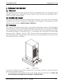
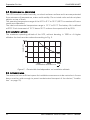
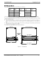
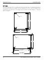
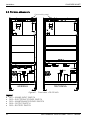
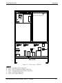
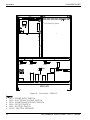
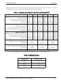
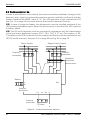
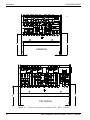
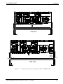
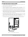

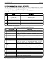
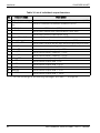
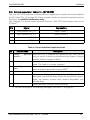
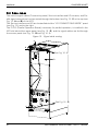
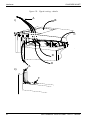
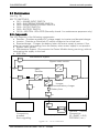
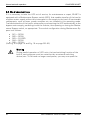
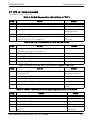
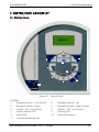
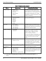
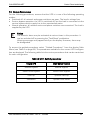
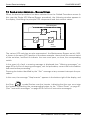
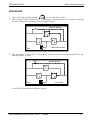
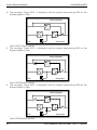
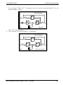
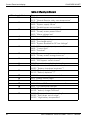
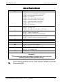
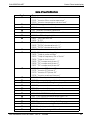
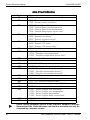
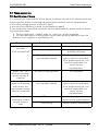
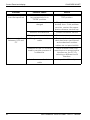

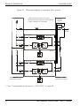
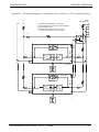
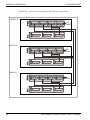
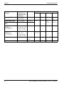
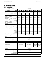
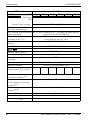
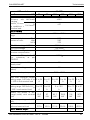
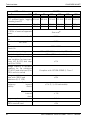
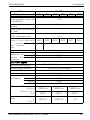


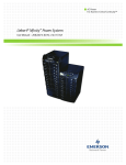


![[输入书名]](http://vs1.manualzilla.com/store/data/005783394_1-fc20c72617a19a0d7587a472ef1576a7-150x150.png)