1
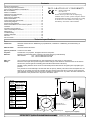
SIDE-POWER Thruster Systems is rd th a p bo ee n K al o u an m Installation and user manual SEP 130/250T IP Ignition Protected thruster assembly P.O. Box 519 N-1612 Fredrikstad Norway Tel: +47 69 30 00 60 Fax: +47 69 30 00 70 w w w. s i d e - p o w e r. c o m s i d e p o w e r @ s l e i p n e r. n o © Sleipner Motor AS 2015 Made in Norway ! SLEIPNER MOTOR AS Contents Contents specifications ......................................................... Contents 2 Contents Technical Technical & specifications.............................................................. Planning important precautions ......................................... 32 DECLARATION OF CONFORMITY nical specifications Technical ......................................................... specifications ......................................................... 2 2 DECLARATION OF CONFORMITY Planning & important precautions.............................................. Stern thruster installation considerations ............................. 3 We,OF Sleipner Motor AS ing & important Planning precautions & important ......................................... precautions ......................................... 3 3 DECLARATION DECLARATION CONFORMITY OF CONFORMITY Sternon thruster installation considerations................................... Bolt installation .................................................................. 43 We, P.O. Sleipner Motor AS Box 519 thruster installation Stern thruster considerations installation ............................. considerations ............................. 3 3 Bolt onon installation ..................................................................... Mould installation ............................................................... 54 Motor We, ASBox Sleipner AS P.O. 519 MotorNorway on installation .................................................................. on installation .................................................................. 4 4 We, Sleipner N-1612 Fredrikstad, MouldBolt on installation .................................................................. Gearhouse and motorbracket ................................................ 65 P.O. Box 519 P.O. Box 519 N-1612 d on installation Mould ............................................................... on motorbracket. installation ............................................................... 5 5 declare that thisFredrikstad, product withNorway accompanying Gearhouse and .................................................... Oil tank & propellers .............................................................. 76 N-1612standard Fredrikstad, N-1612 Norway Fredrikstad, Norway with the declare that this product with accompanying house and motorbracket Gearhouse ................................................ and motorbracket ................................................ 6 6 remote control systems complies Oil tank & propellers.................................................................. Electromotor IP assembly ...................................................... 87 declare that this product declare with that accompanying this product with accompanying standard remote control systems complies with the nk & propellers Oil .............................................................. tank propellers .............................................................. 7 7 essential health and safety requirements according Electromotor IP& assembly. .......................................................... Electrical installation ............................................................... 98 standard remote control standard systems remote complies control with systems the complies essential health and safety requirements according omotorControl IP assembly Electromotor ...................................................... IP assembly ...................................................... 8 8 to the Directive 89/336/EEC of 23 May 1989 with the Electricalpanel installation .................................................................. and control-leads .......................................... 109 essential health safety requirements health andand safety according toand the essential Directive 89/336/EEC ofrequirements 23 May 1989according ical installation Electrical ............................................................... installation ............................................................... 9 9 amended by 92/31/EEC 93/68/EEC. Control panel and control-leads............................................... 10 Visual wiring diagram ........................................................... 11 to the Directive 89/336/EEC to the Directive of 23 May 89/336/EEC 1989 of 23 May 1989 amended by 92/31/EEC and 93/68/EEC. ol panelTechnical and Control control-leads panel .......................................... and control-leads .......................................... 10 Visual wiring diagram............................................................... 11 10 amended by 92/31/EEC wiring diagram ..................................................... 12 amended and 93/68/EEC. by 92/31/EEC and 93/68/EEC. l wiringElectrical diagram Visual ........................................................... wiring diagram ........................................................... Technical wiring diagram ......................................................... 12 11 installation of stern thruster systems 11 ................... 12 nical wiring diagram Technical ..................................................... wiring diagram ..................................................... 12 12 Electrical installation of stern thruster systems ........................12 Checklist ............................................................................... 13 ical installation Electrical of stern installation thruster systems of stern ................... thruster systems 12 ................... 12 Checklist................................................................................... 13 Important user precautions .................................................. 14 klist ............................................................................... Checklist ............................................................................... 13 Important user precautions. ...................................................... 14 13 How to use Sidepower thrusters ......................................... 15 tant user precautions Important .................................................. user precautions .................................................. 14 How to use Sidepower thrusters.............................................. 15 14 Maintenance .......................................................................... 16 to use Troubleshooting Sidepower How to thrusters use Sidepower ......................................... thrusters ......................................... 15 Maintenance............................................................................. 16 15 .................................................................... 17 enanceWarranty .......................................................................... Maintenance .......................................................................... 16 Troubleshooting. ....................................................................... 17 16 statement ............................................................... 18 bleshooting .................................................................... Troubleshooting .................................................................... 17 Warranty statement ................................................................. 18 17 Parts list ................................................................................ 19 anty statement ............................................................... statement ............................................................... 18 Parts Warranty list. ................................................................................... 19 18 Service centres ...................................................................... 20 list ................................................................................ Parts list ................................................................................ 19 Service centres ........................................................................ 20 19 ce centres ...................................................................... Service centres ...................................................................... 20Technical specifications 20 Technical specifications Motor: Custom made Technical reversible DC-motor. specifications Technical specifications Motor: Custom made reversible DC-motor. Gearhouse: Seawater resistant bronze. Ballbearing at propellershaft; combination of ballbearing and slide bearing at : Motor: Custom made reversible CustomDC-motor. made reversible DC-motor. Gearhouse: Seawater resistant bronze. Ballbearing at propellershaft; combination of ballbearing and slide bearing at driveshaft. house: Gearhouse: Seawater resistant Seawater bronze. Ballbearing resistant bronze. at propellershaft; Ballbearingcombination at propellershaft; of ballbearing combination and slide of ballbearing bearing atand slide bearing at driveshaft. Motor bracket: driveshaft. Seawaterresistant driveshaft. aluminium. Motor bracket: Seawaterresistant aluminium. Ignition protection: to ISO 8846 r bracket: Motor Seawaterresistant bracket: Conforms Seawaterresistant aluminium. aluminium. Ignition protection: Conforms to ISO 8846 Propeller: Symmetrical 4 blade kaplan on protection: Ignition Conforms protection: to ISO 8846 Conforms to ISO 8846propeller, fibreglass reinforced composite. Propeller: 5 blade skew "Q"-propeller , fibreglass reinforced composite. recommended battery capacity (cold crank capacity by DIN standard) eller: Batteries: Propeller: Symmetrical 4Minimum bladeSymmetrical kaplan propeller, 4 blade fibreglass kaplan propeller, reinforced fibreglass composite. reinforced composite. Batteries: Minimum capacity SP 75 Ti IPrecommended 12V : 500 CCAbattery DIN / 24V : 250(cold CCA crank DIN capacity by DIN standard) ries: Batteries: Minimum recommended Minimum battery capacity battery crank capacity (cold byCCA DIN crank standard) capacity by DIN standard) SEP130/250T recommended 12V(cold : 750 CCAcapacity DIN/1425 SAE SP TiCCA IP CCA DIN / 24V :/ 350 CCA SP 75 Ti IP 12V 500 SP 7512V TiDIN IP: 700 12V / 24V : 500 :24V 250 CCA DIN DIN 24V : 250DIN CCA DIN :95 :CCA 400 CCA DIN/760 SAE SP 95 Ti IP 12V : 700 SPCCA 95 TiDIN IP 12V / 24V: 700 : 350CCA CCADIN DIN/ 24V : 350 CCA DIN Max. S2 min. or appr. within a limited timeRemaining frame. All run electromotors against overheating. Max. use: use: Up =to3continuous run7-10% time depending on load. time shownare onprotected control panel. Electronic time-lapse device protects against sudden change of drive direction. Electric thermal protects against sudden ofprotected drive direction. Electric thermal cut-offcut-off switch in Safety: use: Safety: Max. S2use: = 3 min. or appr.S27-10% =time-lapse 3 min. within or appr. adevice limited 7-10% timewithin frame. a All limited electromotors time change frame. are All electromotors against are overheating. protected against overheating. electromotor protects against overheating (autoheating reset when electromotor cools down). switch in electromotor protects against over (auto reset when electro motor cools down). Electronic time-lapse Electronic device protects time-lapse against devicesudden protects change against of sudden drive direction. change Electric of drive thermal direction. cut-off Electric thermal cut-off y: Safety: Flexible coupling between electro-motor anddriveshaft driveshaft protects electromotor and gearsystem if down). propeller coupling between and protects electromotor and gearsystem if propeller gets switch in electromotor switch protects in electromotor againstelectro-motor over protects heating against (auto over resetheating when electro (auto reset motorwhen cools electro down). motor cools jammed. gets jammed. Flexible coupling between Flexible coupling electro-motor between and electro-motor driveshaft protects and driveshaft electromotor protects and gearsystem electromotorif and propeller gearsystem if propeller PJC panel shuts of automatically 5 minutes after last use (factory default). This interval can be adjusted in 5 min gets jammed. gets jammed. up toSidepower 60 minutes or turned off completly. PPC Control 6unit wil turnafter off motor power each time Ifsteps original panel is used, the panel The shuts off Speed automatically minutes last use. main solenoids is activated. This removes any possibility for solenoid lock in. Any fault in the main solenoids will Integrated microprocessor solenoids, reducing wear and risk after of solenoid lock-in.after Auto-stop of thruster in If original Sidepower If original panel isSidepower used, themonitors panel panel is shuts used, offthe automatically panel shuts 6 off minutes automatically last6 use. minutes last use. give feed back to the panel and turn off power to the electric motor. case of accidental solenoid lock-in or if run signal is continous for more than 3 minutes. Integrated microprocessor Integrated monitors microprocessor solenoids,monitors reducingsolenoids, wear and reducing risk of solenoid wear and lock-in. risk of Auto-stop solenoidoflock-in. thruster Auto-stop in of thruster in case of accidental solenoid case of accidental lock-in or ifsolenoid run signal lock-in is continous or if run signal for more is continous than 3 minutes. for more than 3 minutes. asure nts ref. / inch A B C D E F G H side nnel dia. Max. tern ckness otor utput ltage Measure ments ref. SP75 Ti IP SP95 Ti IP Measure mm / inch SEP130/250T SP75 Ti IPref. SP95 SP75 Ti IPIP 299mm / 11,77" Ti 407mmSP95 / 16,02" Ti IP A ments 256mm / 10,08" 256mm / 10,08" B mm / inch 299mm 299mm 11,77" 200mm407mm A 200mm407mm / 7,87"// 16,02" / 7,87" / 16,02" C / 11,77" 340mm 256mm 256mm 10,08" 337mm256mm 256mm 10,08" B 337mm / 13,3"///13,4" / 13,3" / 10,08" D / 10,08" 250mm 200mm 200mm / 7,87" 7,87" ø300mm200mm 200mm C ø300mm / 11,8"/ /9,84" / 11,8" / 7,87" E / 7,87" 350mm 337mm 337mm / 13,3" 13,3" ø200mm337mm 337mm D ø200mm / 7,84"/ /13,8" / 7,84" / 13,3" F / 13,3" ø300mm ø300mm 11,8" ø300mm // 11,8" ø300mm E6x ø10,5mm / 0,41" 6x ø10,5mm / 0,41"/ 11,8" G / 11,8" ø200mm ø200mm 7,84" ø129mmø200mm ø200mm F ø129mm / 5,08" // 7,84" / 5,08" / 7,84" H / 7,84" 6x ø10,5mm 6x ø10,5mm ø10,5mm // 0,41" 0,41" 6x 6x ø10,5mm / 0,41" G Inside / 0,41" ø129mm ø129mm 5,08" 185mmø129mm H 185mmø129mm / 7,28" // 5,08" / 7,28" / 5,08" tunnel/ 5,08" dia. Inside D 250mm 185mm 185mm/ //9.8" 7,28" 185mm 7,28" 185mm / 7,28" tunnel Max./ 7,28" dia. 54mm / 2,13" 54mm / 2,13" stern 60° thicknessMax. 105mm/4.1” 54mm / 2,13" 54mm // 2,13" 2,13" 54mm 54mm / 2,13" stern Motor 4,4 KW / 6 HP 4,4 KW / 6 HP outputthickness Motor 12 / 6,5 24 Volt Volt Voltage kW HP 12 / 24 4,4 KW / 6 HP 4,4 KW///8.7 HP 4,4 KW 66 HP 4,4 KW / 6 HP output 12 / 24 Voltage Volt 12 // 24 24 Volt Volt 12 12 / 24 Volt Cut out in stern: F W.L. W.L. W.L. B B B C C C D 60° D 60° Bolt holes dia: G Bolt position radius: H Bolt holes dia: G Bolt holes dia: G Bolt position radius: H Bolt position radius: H Outside of flange: E A A Support (user supplied) SP75Ti / SP95Ti ignition protected thruster assembly 1.2.1 - 2007 SEP130/250T IP Ignition Protected thruster assembly version.1.3 - 2015 SP75Ti / SP95TiSP75Ti ignition/ protected SP95Ti ignition thruster protected assembly thruster 1.2.1assembly - 2007 1.2.1 - 2007 Cut out in stern: F Cut out in stern:Outside F of flange: E A Outside of flange: E 2 2 2 2 Planning and important precautions Prior to installation, it is important that the installer reads this guide to ensure necessary acquaintance with this product. If the height in the room you are installing the Sidepower is limited, the Sidepower can be installed horizontally or at any angle in between. - If the electro motor is positioned more than 30° off vertical, it must be supported separately. - The electromotor must be handled carefully. Do not lift it by the internal connections/main terminals or put it down on the driveshaft. - Beware to keep installation within advised measurements. No part of the propeller or gearhouse must be outside the tunnel. The electromotor, its components, contacts / plugs or other joints in the control cables must be mounted so that they will keep dry at all times. We advice to paint the gearhouse and propellers with antifouling. PS! Do not paint the anodes, sealings or propellershafts. Do not finish the inside of the tunnel with a layer of gelcoat / topcoat or similar. It is only room for a thin layer of primer and two layers of anti-fouling between the tunnel and the props. With the boat on land, only run the thruster for a fraction of a second, as without resistance it will accelerate very fast to a damaging rpm. Also, while the thruster is in air, make sure that the propellers have come to a complete stop before performing a directions change of the thruster, as it might cause damage to the thruster. The PPC Power control unit should be installed in a dry, ventilated place - cable connections facing down. Mount unit with battery positive cable branching out at unit terminal, not at thruster motor. Allow free space at min 200mm over and min 100mm in front and at sides.Take into consideration that a 5 m multicable shall be plugged in between thruster motor and PPC unit. This manual is intended to support educated/experienced staff and is therefore not sufficient in all details for the correct installation. Do not store items close to the thruster motor as it gets hot as well as any loose items near the thruster motor can cause problems with electrical wiring coming loose and short-circuiting. When installed in boats approved or classified according to international or special national rules, the installer is responsible for following the demands in accordance with these regulations / classification rules. The instructions in this guide can not be guaranteed to comply with all different regulations/classification rules. These instructions are only general instruction. If you are not skilled to do this work, please contact professional installers for assistance. NB! Faulty installation of the tunnel, thruster, PPC Power Control unit or panel will render all warranty given by Sleipner Motor AS void. Stern thruster installation considerations To achieve maximum effect, reliability and durability from your Sidepower stern thruster, a correct installation is very important. Please follow the instructions carefully, and make sure that all checkpoints are carefully controlled. Additional considerations for positioning of the stern thruster Make sure that the stern-tunnel does not disturb the waterflow under the hull Ensure that when installed the thruster does not foul exisiting equipment inside the boat like steerage links etc. Make sure that the water flow from the thruster are not intereferred to much by sterndrives, trimtabs etc. as this will reduce the thrust considerably. It is possible to mount the tunnel off the boat’s centre line if necessary. If the stern thickness is to much for the thruster in question you can easily remove hull material in the necessary area to fit the thruster. You only have to reduce the stern thickness down to the max. thickness measurement in the drawing. SEP130/250T IP Ignition Protected thruster assembly version.1.3 - 2015 3 SEALANT Fig. 2 Fig. 1 WASHERS LOCKNUT OR DOUBLE NUTS SEALANT Bolt on installation of the stern tunnel 1. Make sure that there are enough space both inside and outside the transom of the boat. 2. Once the place for the installation has been decided, hold the tunnel in place in the horizontal position and mark the bolt holes. Remove the tunnel and it is then possible to calculate and mark the centre. 3. It is important that the tunnel flange sits flush on the transom. If this is not so, then the area on the transom will have to be flattened to ensure a snug fit. PS ! Take care with grinders as it is very easy to remove to much in fibreglass At this time, cut out the centre hole and the transom to the same internal diameter as the tunnel flange and drill the bolt holes. Before bolting on the stern tunnel, the prepared area must be sealed with a gelcoat or similar to ensure there is no water ingress into the hull. If a bow thruster is also installed, we strongly advice to use separate battery banks for the two thrusters to avoid extreme voltage drop if both thrusters are to be used at the same time. Refer to the thruster manuals for adviced battery capacity and cable sizes for each thruster. Also ensure that you do not have direct connections of both + and - if you have built together controls for both thrusters to avoid current leakage between separate battery banks. If you are installing the standard Sidepower dual joystick panel this is already secured. 4. Before fitting the tunnel to the transom, fit the lower gear leg to the tunnel as described on page 6. 5. When fitting the tunnel, ensure that there is ample sealant (Sikaflex or similar) in the sealing tracks of the tunnel flange and around the bolts to make a water tight fitting (Fig. 1/2). Bolts, washers and nuts are not included as they will wary depending on the transom thickness We recommend A4 stainless with A4 lock nuts and A4 washers of a large diameter on both outside and inside. Bolts diameter: ø 10mm or 3/8” stainless steel 6. Refer to the installation manual for the recommended thruster fitting. SEP130/250T IP Ignition Protected thruster assembly version.1.3 - 2015 4 Fig. 1 SP 75 Ti SP 95 Ti Fig. 2 SP125Ti BOATS CENTRELINE Fig. 3 Fig. 1 BOATS CENTRELINE TUNNELS CENTRELINE TUNNELS CENTRELINE Ø 9mm 0,35" 28,0mm 1,1" Ø 32mm 1,26" Ø 46,00mm 1,81" 7 Ø 11,00mm 7/16" 40,0mm 1,57" Fig. 4 Fig. 7 2 1 IL RO GEA 90 P E Fig. 3 Bolt tightening forces: Fig. 2 Bolts (2x) holding gearhouse to bracket: SP 75 Ti / SP 95 Ti: 17 Nm (12,4 lb/ft) SP 125 Ti: 33 Nm (24 lb/ft) SLEIPNER 3 4 Fig. 5 SP 75 Ti SP 95 Ti Bolt tightening forces: P Fig. 6 Bolts (2x) holding gearhouse to bracket: SP125Ti 33 Nm (24 lb/ft) PORT PORT STARBOARD P S S PORTSTARBOARD STARBOARD Fitting gearhouse and motor bracket D Fitting gearhouse and motor bracket Getriebe und Motorhalterung 1. Try the lower-unit in the tunnel (remove the anodes) first by using the gasket inside the tunnel. Try on the propellers to make sure it k the centreline of theintunnel and the SP75Ti 1. Die Mittellinie Tunnel Boot(Fig. markieren. is centred the tunnel andboats turn centreline. freely with the same clearance from eachvon blade to theund tunnel 1). 95Ti: The gearhouse must be fitted with the gearhouse lid (the SP 75 Ti / SP 95 Ti: Damit Schubrichtung und Kontrollpanel ewed in lid one ofmust the propellers) on the side of über-einstimmen, das S Getriebegehäuse so einbauen, behind The gearleg be fitted with the starboard end marked P facing port and the end marked facing starboard (Fig. 3) for the daß thrustder direction boat for theto thrust direction to correspond with the control Getriebegehäuses verschraubte Verschluß correspond with the control panel. If there is panel no visible P Ver-schluß or S marks,des fit the gearleg with the(der "SLEIPNER"-casting towards the . 5). SP 125stern/back Ti: Fig. 6 of the boat. hinter einem der beiden Propeller) Richtung Steuerbord zeigt (Fig. 5). the gearhouse gasket (7) to mark the centre of the holes and Ti: itFig. 6 2. the Apply a thin layer ofPlace sealant both sides ofboats the gasket (7)SP and125 place carefully on the gearhouse, making sure no sealant gets ble check measurements. theon thruster in the into the bolt holes on the gearhouse (Fig 1). 2. Die Löcher mit der Dichtung (7) markieren. Maße überprüfen! treline with the bolt hole as the centre (Fig. 1). It is absolutely Den Thruster schiffssmittig plazieren (Fig. 1). Da der Abstand essary that all holes are in-line with the tunnels’ centreline to 3. Push the gearhouse through the main hole push thePropellern gearhouse und and Tunnel motor-bracket together. zwischen wegengently größtmöglicher ure precise installation, as the clearance between the in the tunnel and Performance minimal konstruiert ist, müssen für eine präzise pellers and the tunnel is minimal to ensure best possible alle the Löcher der Tunnelmittellinie ormance. 4. Fit the enclosed sealing washers to the bolts and screw theInstallation lower unit and motorauf bracket together with theliegen. two provided bolts. withwhere 33 Nm / 24 lb/ft bracket (Fig. 2). is to be placed, 3. Im Bereich der Motorhalterung darf kein Laminat auf dem re must be Tighten no casting the motor Tunnel sein, da dies zu einem Getriebeschaden führen kann. his will cause possible failure of the gearhouse. The motor Liegt die Motorhalterung nicht eben auf dem Tunnel auf, so cket must fit steady on the tunnel, if the tunnel is not smooth, sind sämtliche Unebenheiten in diesem Bereich abzuschleifen. umps or uneven parts must be grinded smooth. the centre-hole ø 32mm and then the two screw-holes ø 9mm. -fill the gearhouse with gear oil type EP90 through the oil drain ew (4). Make sure to get the copper gasket (3) on again. 4. Bohren Sie das Zentrumsloch (ø 32 mm) und dann die beiden Schraubenlöcher (ø 9 mm). 5. Das Getriebegehäuse mit Getriebeöl EP90 durch die Öffnung der Ölablaßschraube (4) befüllen. Kupferdichtung (3) einsetzen. the lower-unit in the tunnel (without the zinc anodes and the 6. Das Getriebegehäuse (ohne Zinkanoden und unteren Teil der er part of the flexible coupling) by using the gasket inside the elastischen Kupplung) unter Verwendung der Dichtung in den nel. Try on the propellers to make sure they are in the middle of Tunnel einpassen. Den Propeller auf die Achse stecken; dieser tunnel and turn freely with the same clearing from each blade to muß sich frei bewegen lassen und jedes Propellerblatt muß tunnel. Use sealant e.g. Sikaflex to ensure that no leakages den gleichen Abstand zum Tunnel aufweisen. Ist die Tunnelur. innenseite ungleichmäßig, etwas Sikaflex o.ä. auftragen, Make sure that no sealant gets in to the oil-holes (2). damit keine undichte Stelle auftritt. ke sure that there is some oil or grease on the O-rings in the PS ! Die Durchgänge für das Öl (2) von Dichtmasse freihalten. or bracket before mounting it together with the gearhouse. 7. Etwas Öl oder Fett auf die O-ringe der Motorhalterung geben, h the gearhouse through the main hole in the tunnel and push da diese sonst beim Montieren beschädigt werden können. gearhouse and motor-bracket gently together. 8. Das Getriebegehäuse durch das Hauptloch im Tunnel führen ew the lower unit and the motor-bracket together with the two und vorsichtig mit der Motorhalterung zusammenschieben. vided bolts (Fig. 7). 9. Das Getriebegehäuse und die Motorhalterung mit Hilfe der beiSEP130/250T IP Ignition Protected thruster assembly version.1.3 - 2015 den Bolzen verschrauben (Fig. 7). 2 SP 75 Ti / SP 95 Ti / SP 125 Ti 2.5.1- 2007 5 5 1 2 3 4 Locktite Fitting propellers 1. Turn the propeller shaft so that the drivepin (5) is in a horizontal position and ensure that it is centred in the propellershaft. 2. Push the propellers onto the shaft with the track for the drivepin in an horizontal position (same direction as you set the drivepin), all the way in. There should be almost no gap between the propeller hub and the gearhouse. 3. Place the washer (4) on the prop.shaft and then tighten the lock-nut (3) on the propeller shaft. 4. Place the anode (2) in its designated position and tighten the anode holding screw (1). Apply a thread glue (Locktite or similar) to ensure that the anode holding screw does not un-screw itself from the propellers rotation. Parts description: 1 : Screw for anode 2 : Anode 3 : Propeller lock nut 4 : Washer 5 : Drivepin for propeller SEP130/250T IP Ignition Protected thruster assembly version.1.3 - 2015 6 SP75Ti: 33 Nm (24 lb/ft) SP95Ti: 33 Nm (24 lb/ft) Bolt tightening force (2x): SP75Ti: 17 Nm (12,4 lb/ft) SP795Ti: 17 Nm (12,4 lb/ft) Fig. 1 SP95Ti IP Bolt tightening force (4x): Fitting the electromotor IP assembly 33 Nm (24 lb/ft) 1. Remove the 4 bolts in the motorbracket. 2. Mount the lower part of the flexible coupling and tighten the set screws (two for SP75Ti IP, one for SP95TI IP). Insert the "rubber/ plastic ring" in this lower part. 3. Place the motor gently on the motorbracket. Be careful, the motor is heavy! Ensure that the "rubber/plastic ring" goes into position. 33 Nm (24,4solb/ft) Ensure that you are placing the motor that the cable terminals on it are available for electric installation later. 4. Fasten the motor to the bracket with the 4 bolts and tigthen them. 5. If you are installing a SP95Ti IP in an angle of more than 45o off a vertical position, the electromotor needs a separate/additional See illustration in the measurements drawings. 6. Lift the lower part of the flexible coupling together with the rubber/plastic ring into the upper flexible coupling. The rubber/plastic ring must be in its correct position in the upper part, fully inserted but not com-pressed against it (SP75Ti IP:17 mm - SP95Ti IP: 2mm). Secure the lower part of the flexible coupling in its new position by tightening the set-screws (two for SP75Ti IP, one for SP95TI IP). Bolt tightening force (2x): Fig. support. 2 Fitting the electromotor IP assembly Final gearleg assembly 1. Remove the 4 bolts in the motorbracket. 2. NB !part Paintofthe and propeller forring propellers prevent growth of barnacles or (include similar which Insert the lower thegearhouse flexible coupling andwith theantifouling red plastic on thetogear shaft. Place the motor the would upperreduce part ofthe performance dramatically. Do not paint the propeller shaft, the zincanodes or the end face of the gearhouse. the flexible coupling) on the motor bracket. Fasten the motor to the bracket with the 4 bolts and tighten them. Lift the lower part of the flexible coupling together with the plactic ring into the upper part of the fleixible coupling. The plastic ring must be in its correct position in the upper part, fully inserted, but not compressed against it (2mm). Secure the lower part of the coupling in its new position by tightening the set-screw. 3. If you are installing the thruster in an angle of more than 45 deg. off a vertical position, the electromotor needs a separate/ additional support. See illustration in the measurements drawings. SP75Ti / SP95Ti ignition protected thruster assembly 4. 1.2 - 2005 8 Check the system by turning the propeller, it will be a little hard to turn (because of the gear reduction and the motor), but you should be able to turn it by hand. Final gearleg assembly NB ! Paint the gearhouse and propeller with antifouling for propellers to prevent growth of barnacles or similar which would reduce the performance dramatically. Do not paint the propeller shaft, the anodes or the end face of the gearhouse. SEP130/250T IP Ignition Protected thruster assembly version.1.3 - 2015 7 Fig. 1 NB: The Proportional Power Controller is a bulkhead (wall) mounted unit and must be installed in a dry and well ventilated compartment. The unit also requires a 200 mm minimum head clearance and a 100 mm minimum clearance surrounding its remaining outer casing. Fig. 2 Battery & cable recommendations: Model SEP130/250T Voltage Nominal Min. battery current CCA draw >7m total + & - 7-14m total + & - 15-21m total + & - 22-28m total + & - 28-35m total + & - 36-45m total + & - Min. Rec. Min. Rec. Min. Rec. Min. Rec. Min. Rec. Min. Rec. 12 V 740 A DIN: 750 SAE: 1425 mm2 AWG 95 3/0 95 3/0 2x 70 2x 2/0 2x 95 2x 3/0 2x 95 2x 3/0 280* 250* 375* NA NA NA NA 24 V 340 A DIN: 400 SAE: 760 mm2 AWG 35 1 50 1/0 50 1/0 70 2/0 60 2/0 95 3/0 95 3/0 120 4/0 120 4/0 2x 95 2x 3/0 2x95 2x 3/0 2x 120 2x 4/0 Minimum and recommended cable dimensions can be identical due to safety margins and cable heat considerations for short cable lenghts. * Minimum or recommended cable cross section in mm2 Electrical installation • Explanation of electrical table - All cable lengths are the total of A+B+C+D+E in Fig. 1. - Battery size is stated as minimum cold crank capacity, not Ah. - Use slow fuse rated to hold stated Amp-Draw for min. 5 minutes. • It is important that you use a good cable size and batteries with a high cranking capacity to feed the thruster, because it is the actual voltage at the motor while running the thruster that decides the output rpm of the motor and thereby the actual thrust. Please see the list above for advised min. sizes of cables and batteries. You can of course use larger cables for even better results. • A main switch that can take the load without noticeable voltage drop must be installed in the main positive lead so the power for the thruster can be turned off independent of the rest when not on board or in emergencies. This should be placed in an easy accessible place and the boats instructions should inform that this should be turned off like the boat’s other main switches. • We also advice to install a fuse in the positive lead for protection against short circuiting of the main cables. This fuse should be of a adequate quality which normally means that it is physically large as these have less voltage drop than the simple / small ones. It should be of the slow type and sized to take the amperage draw for at least 5 minutes. • It is highly recommended to install a Sidepower Automatic Main Switch 897712 (12V) eller 897724 (24V). The AMS will be activated when the panel is turned on, contains an automatic short circuit fuse and a manual emergency stop. The AMS will also provide feedback to the panel regarding evt. faults. • The cable ends must be fitted with terminals and these must be well isolated against contact with anything but the proper connection point. • Terminals must be properly tightened. Secure/hold inner nut when tightening (Fig. 2). Tighten ø10mm / 3/8" bolt with 15 Nm/11lb/ft. NB! Very important to check the following with mainswitch in off position: After all electrical connections have been completed check with an ohm meter that there is no electrical connection between electro motor flange and positive terminal on the motor and between the electro motor flange and the negative (A1) terminal on the motor. If you feel unsure on how to perform this check, contact skilled personnel for guidance. SEP130/250T IP Ignition Protected thruster assembly version.1.3 - 2015 8 Control panel and control-leads Control panel installation: • You can install as many panels as you wish by using optional Side-Power S-link T-connectors If two or more panels are operated at the same time in opposite directions, the thuster will stop. When two or more panels is operated in the same direction, the thruster output will be determined by the panel giving the largest signal. • When using original Sidepower equipment it is all “plug & go”. • The mechanical installation of the panel is described in the manual following the panel. • The thruster control panel should be placed in a position were it is easy to use, and it is very common to use the thruster at the same time as your gear/throttle lever so it is normally a user friendly solution to be able to access these with one hand for each control. SEP130/250T IP Ignition Protected thruster assembly version.1.3 - 2015 9 SEP130/250T IP Ignition Protected thruster assembly Wiring diagram version.1.3 - 2015 10 SEP130/250T IP Ignition Protected thruster assembly Technical wiring diagram, thruster motor version.1.3 - 2015 11 Checklist Propellers is fastened correctly to the shaft. Propellers turns freely in tunnel. The anodes holding screw is tightened well with thread glue. Anti-fouling have been applied to the gearhouse and propellers but NOT on the anodes or the gearhouse lid where the propellers is fastened. The brush springs are fitted correctly on the brushes in the electro-motor (check through the grid around the top end of the motor). Correct drive direction as per control panel. All electrical connections are clean, dry and tight, and the correct cable, fuse and main switch sizes have been used. With a ohm meter check that there is no electrical connection between electromotor body and positive terminal on the motor and between the electromotor body and the negative (A1) terminal on the motor. The bolts holding the gearhouse and motorbracket together are tightened correctly. The bolts holding the electromotor to its bracket are tightened correctly. The 4 main cables connected to 3 terminals on PPC is placed correctly and properly fixed to avoid mecanical stress on the termi- nals Very important for IP protection: The main power cables have securely been connected as described. The control lead ends out of the explosive area and has been properly fitted and secured against damage. The thruster has been installed as per the instructions in this manual and all points in checklist above have been controlled. Signed: ..................................... Date: ....................................... Extra pre-delivery tests by installer / yard who does not use other quality control systems ! Thruster type: ................................................. Voltage: ...................... Serial number: ..................................................................................... Date of delivery: .................................................................................. Correct drive direction as per controlpanel: ....................................... Voltage at thruster when running: ...................................................... Battery cable size used: ..................................................................... The compartment where the thruster is fitted is isolated from general bilge water and has no obvious or suspected risks for flooding. Other comments by installer: SEP130/250T IP Ignition Protected thruster assembly version.1.3 - 2015 12 Important user precautions • Ensure that you know the location of the main battery switch(es) that disconnects the thruster(s) from all power sources (batteries) so that the thruster(s) can be turned off in case of a malfunction. • Always turn the main power switch off before touching any part of the thruster, as an incidental start while touching moving parts can cause serious injuries. • Always turn the control device off when the thruster is not in use. • The electromotor has a built in thermal sensor that will shut off the electromotor if it is overheating and re-engage it when it has cooled down some. This should be considered when planning your manoeuvring. The panel will show the temperature status of the thruster. • Running the thruster at reduced effect results in less heating of the thrusters, significantly extending the operating time. Information about thruster runtime is displayed on the PJC panel • Never use a thruster close to somebody in the water, as the thruster will draw objects close by into the tunnel and contact with the rotating propellers will cause serious injuries. • With the boat on land, only run the thruster for a fraction of a second, as without resistance it will accelerate very fast to a damaging rpm. Also, while the thruster is in air, make sure that the propellers have come to a complete stop before performing a directions change of the thruster, as it might cause damage to the thruster. • If the thruster stops giving thrust while the electromotor is running, chances are that there is a problem in the drive-system. You must then immediately stop trying to run it, and turn it off, as running the electromotor for more than a few seconds without resistance from the propeller, can cause serious damage to the electromotor. • When leaving the boat always turn off the main power switch for the thruster. • We advice to always keep the main engine(s) running while using a thruster. This will keep the batteries in a good charge condition. This will also give better performance to the thruster, as a higher voltage at the thruster results in a higher torque (power) in the electromotor. • Please note that the performance of a thruster strongly depends on the voltage available at the electromotor. This voltage will decrease by time because aging batteries have a reduction of capacity. By installing new batteries the effect of the thruster should be back at the original level. • Make sure that only one control is used at the same time, if two panels are operated in opposite directions at the same time the thruster will not run at all. If they are operated in the same direction the thruster will run with the largest power given by the two panels. • If the thruster is not performing or functioning as usual, the cause for this must be found and corrected as soon as possible so to avoid causing any other or further damage to the equipment. You must also turn off the main battery switch immediately in case the problem is of electric origin. • Never store anything (e.g. equipment, sails, ropes etc.) in the same compartment as the thruster. When the thruster runs for a longer period it will get hot and will cause damage. Warning: Tampering with the Ignition Protected stern thruster assembly or any attempt to disassemble anything on this thruster assembly inside the boat can cause an explosion with very serious consequences. If there is a problem with your Ignition Protected stern thruster, please contact your dealer. Danger: NEVER Disassemble any part of the Ignition Protected stern thruster assembly SEP130/250T IP Ignition Protected thruster assembly version.1.3 - 2015 13 • Connectorforexternal“buzzer”/loudaudiblealarms Speedcontroljoystickfor bowthruster Holdingfunctionforautorunningofbowandstern thrusterstogetherinthe directionofthearrowsat selectedpower Press“+”formoreand “-”forlesspower. Speedcontroljoystickfor sternthruster Informationdisplay,see nextpagefordetails. Pressboth“ON”buttons simultanouslytoactivate controlpanel. MENU Presstode-activate controlpanelorcancelor gobackinmenusystem Presstochange Presstoaccessmenu betweendayand systemandchoose nightlight itemsinmenus SIDE-POWER THRUSTER SYSTEMS CONFIDENCE BY CONTROL User info, PJC-212 - 1/ How to use Sidepower thrusters How to use a bowthruster 1.Turn main power switch for the bowthruster on. (Always turn off the main power switch when not onboard.) A Side-Power Automatic Main Switch wil turn on/off when the panel is turned on/off 2.Please take some time to exercise thruster usage in open water to avoid damages to your boat. 3.Turn the control panel on by pushing both “ON” buttons on the original Side-Power panel simultaneously. 4.Move the joystick in the direction you wish the bow to move. Other controls like footswitches or toggle-switches on the throttle can be used. These are connected to the S-link control system by a S-link interface (Refer to schematics in interface manual for installation 5.Depending on the sideways speed of the bow, you must disengage the control device shortly before the bow is in the desired direction, as the boat will continue to move after stopping the bowthruster. How to use a single stern thruster Some boats might however have installed a single stern thruster because of space limitation in the bow. In this case the stern thruster is used in the same way as a single bow thruster or moving the boat’s stern. How to use a bow and stern thruster combined The combination of a bow and stern thruster offers total manoeuvrability to the boat and the opportunity to move the bow and the stern separately from each other. This enables you to move the boat sideways in both directions and to turn the boat around its own axis staying at the same place. Refer to the PCJ control panel manual for detailed instructions. • Again, if in doubt, try in open water first! SEP130/250T IP Ignition Protected thruster assembly version.1.3 - 2015 14 1 1 2 2 3 4 5 6 3 5 7 4 6 Power & control cables Ignition protected casing Motorbracket for holding motor and gearhouse together on the tunnel. Flexible coupling secures the electromotor if propeller is jammed. Changeable from inside the boat. 5-blade skew Q-PROP propeller for ultimate performance. Prefilled &sealed gearleg. Changeable anode protects gear-house from corrosion in seawater. 7 5 5 1 2 3 4 5 Fastening screw for anode Anode Propeller lock nut Washer Drivepin for propeller 1 1 2 2 3 3 4 4 Locktite Locktite Maintenance » Keep the propeller and gearhouse clean from growth by painting with antifouling before every season. PS ! The anode, sealing and propeller shafts must abso-lutely not be painted. Be careful that you don't fill paint in the "tracks" in the gearhouse that the propeller hub moves in. » Change the anode before every season, or when about half the anode is gone. Always use a sealant on the screw holding the anode to ensure that it does not fall off. Please observe that in some waterconditions it can be necessary to install an extra anode to ensure that it lasts for the whole period between regular service lifts of the boat. Consult your dealer for information on how to do this. » As a part of the seasonal service of your boat, and before every season, always check that: • The propeller is securely fastened • The bolts holding the electric motor to the motorbracket are fastened correctly. • The area where the thruster is installed is clean and dry. If there are signs of water you must try to find the source and eliminate it. • All electrical connections are clean and fastened firmly. • Make sure that your batteries are in a good condition so that the thruster gets a good voltage. Old or bad batteries will give a reduced performance from the thruster. Warning: Tampering with the Ignition Protected stern thruster assembly or any attempt to disassemble anything on this thruster assmebly inside the boat can cause an explosion with very serious consequences. If there is a problem with your Ignition Protected stern thruster, please contact your dealer. Danger: NEVER Disassemble any part of the Ignition Protected stern thruster assembly SEP130/250T IP Ignition Protected thruster assembly version.1.3 - 2015 15 Trouble shooting Before seeking assistance at the help desk of your Sidepower dealer/distributor please perform these tests and make notes of all measurements to ensure that they have as much information as possible to work on. NB! All check points and solutions must be carried out after consulting the relevant information elsewhere in this manual to under-stand how the system is intended to work. If you are unable to understand what to check, you must consult a professional. Solution Check » » The electromotor runs, but there is no thrust. If the flexible coupling between the motor and driveshaft is not fitted correct inside the boat. Check the flexible coupling/shear pin and the motor installation to ensure correct connection of the flexible coupling before re-fitting the electromotor. Are the propellers in the tunnel fastened correctly on the prop-shaft (key/drive pin present) Re-fasten or replace the propeller and/or key/drive pin. With the motor removed, turn the driveshaft from inside the boat to feel if the gears are engaging and turning the prop-shaft. In case of a failure inside the gearhouse, we advice to get a replacement gear-house instead of attempting to repear the internal gear and bearing system. The thruster does not start at all or works only in one direction. Refer to the PCJ Control Panel manual for detaild explanations of fault codes shown in panel display. » The thruster has an unexpected low performance. Check voltage at thruster battery when running. If less than 10,5 V / 21V the thruster will not perform at specified effect. Check that the propeller, gearhouse and tunnel is free from growth/barnacles etc. If there is growth in the tunnel, this will disturb/block the waterflow and especially barnacles on the propeller will greatly reduce performance. SEP130/250T IP Ignition Protected thruster assembly version.1.3 - 2015 16 Warranty statement 1.The equipment manufactured by Sleipner Motor AS (The “Warrantor”) is warranted to be free from defects in workmanship and materials under normal use and service. 2.This Warranty is in effect for of two years from the date of purchase by the user. Proof of purchase must be included, to establish that it is inside the warranty period. 3.This Warranty is transferrable and covers the product for the specified time period. 4.In case any part of the equipment proves to be defective, other than those parts excluded in paragraph 5 below, the owner should do the following: (a) prepare a detailed written statement of the nature and circumstances of the defect, to the best of the Owner's knowledge, including the date of purchase, the place of purchase, the name and address of the installer, and the Purchaser’s name, adress and telephone number; (b) the Owner should return the defective part or unit along with the statement referenced in the preceding paragraph to the warrantor, Sleipner Motor AS or an authorized Service Centre, postage/shipping prepaid and at the expense of the Purchaser; (c) if upon the Warrantor’s or Authorized Service Centre’s examination, the defect is determined to result from defective material or workmanship, the equipment will be repaired or replaced at the Warrantor’s option without charge, and returned to the Purchaser at the Warrantor’s expense; (d) no refund of the purchase price will be granted to the Purchaser, unless the Warrantor is unable to remedy the defect after having a reasonable number of opportunities to do so. Prior to refund of the purchase price, Purchaser must submit a statement in writing from a professional boating equipment supplier that the installation instructions of the Installation and Operation Manual have been complied with and that the defect remains; (e) warranty service shall be performed only by the Warrantor, or an authorized Service Centre, and any attempt to remedy the defect by anyone else shall render this warranty void. 5.There shall be no warranty for defects or damages caused by faulty installation or hook-up, abuse or misuse of the equipment including exposure to excessive heat, salt or fresh water spray, or water immersion except for equipment specifically designed as waterproof. 6.No other express warranty is hereby given and there are no warranties which extend beyond those described in section 4 above. This Warranty is expressly in lieu of any other expressed or implied warranties, including any implied warranty of merchantability, fitness for the ordinary purposes for which such goods are used, or fitness for a particular purpose, and any other obligations on the part of the Warrantor or its employees and representatives. 7.There shall be no responsibility or liability whatsoever on the part of the Warrantor or its employees and representatives for injury to any person or persons, or damage to property, loss of income or profit, or any other consequential or resulting damage or cost which may be claimed to have been incurred through the use or sale of the equipment, including any possible failure or malfunction of the equipment, or part thereof. 8.The Warrantor assumes no liability for incidental or consequential damages of any kind including damages arising from collision with other vessels or objects. 9.This warranty gives you specific legal rights, and you may also have other rights which vary from country to country. SEP130/250T IP Ignition Protected thruster assembly version.1.3 - 2015 17 20 SEP130/250T IP Ignition Protected thruster assembly 5 9 18 4 3 15 17 1 7 6 8 2 16 10 11 14 19 2 13 12 1 8 12 3 4 13 5 Bolt, motor to flange Propeller washer Propeller drivepin Propeller 3 2 1 Locknut Anode 5 4 Driveshaft key Gasket 7 Gearleg bolt 6 Complete gearleg 9 8 921305 Flange Bracket 11 10 10 1271RH 9 1241 20 1181 10 1260 20 1180 9 0610 10 1440 10 1080 9 0601 10 0501 11031 201360 N/A 7 1457 7 1458 7 1457 N/A 10 1440 9 0106 12 12V Bolt, flange to bracket 12 13 Coupling, gearleg side Complete motor bracket 15 14 Coupling, engine side Rubber element 17 16 Key for eletric motor shaft Complete flexible coupling 19 Complete IP electric motor assembly 18 20 Ref: 09/07 < Model period 10 1271RH 9 1241 20 1181 10 1260 20 1180 9 0610 10 1440 10 1080 9 0601 10 0501 921305 11031 201360 N/A 7 1457 7 1458 7 1457 N/A 10 1440 9 0107 24 24V Part # SEP 130/250T Original model SEP130/250T IP version.1.3 - 2015 18 SEP130/250T IP Ignition Protected thruster assembly version.1.3 - 2015 19 Worldwide sales and service www.side-power.com SLEIPNER MOTOR AS P.O. Box 519 N-1612 Fredrikstad Norway Tel: +47 69 30 00 60 Fax:+47 69 30 00 70 www.side-power.com [email protected]