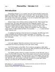
1
Please fill out the following information for quick reference:
Provider:_________________________________________________________________________
Address:_________________________________________________________________________
Phone Number:__________________________
Purchase Date:___________________________
*INFMANU4392*
TRAVEL SCOOTER FEATURES TABLE
Model
Ä
36
40X
44X
40E
44E
40LX
44LX
53
53HD
54
54HD
73
74
83
84
Console Style
A
B
C
Battery Pack Style
D
y
y
y
A
B
Battery Charging
Frame Lock‐up Style
A B C
On Unit
Off Unit
(Release Lever )
(Lock‐up Pin)
y
y
y
y
y
y
y
y
y
y
y
y
y
y
y
y
y
y
y
y
y
y
y
y
y
y
y
y
y
y
y
y
y
yAU only
yAU only
y
y
y
y
y
y
y
y
y
y
y
y
y
y
y
y
y
y
y
y
y
y
Options *
Suspension Seat Post
Lights
Changeable Color Panels
y
y
y
y
y
y
y
y
y
y
y
y
y
y
y
y
y
y
y
y
y
y
y
y
y
y
y
y
y
y
y
y
y
y
y
*NOTE: Travel Scooter options vary by country. Please contact your Provider to determine which options
are available for your Travel Scooter.
NOTE: Please become familiar with your Travel scooter’s model number. The number can be found
on the product specification sheet in your owner’s package. Throughout this owner’s manual, Travel
Scooter attributes are indentified by model number (far left-hand column on Travel Scooter Features
Table). Knowing your unit’s model number will aid you in determining your particular Travel Scooter’s
unique characteristics.
INTENDED USE
The intended use of the Travel Scooter device is to provide mobility to persons limited to a seated position
that have the capability of operating a scooter.
NOTE: This owner’s manual is compiled from the latest specifications and product information
available at the time of publication. We reserve the right to make changes as they become necessary.
Any changes to our products may cause slight variations between the illustrations and explanations in
this manual and the product you have purchased. The latest/current version of this manual is available
on our website.
NOTE: This product is compliant with WEEE, RoHS, and REACH directives and requirements.
This product is manufactured by:
Pride Mobility Products Corporation
182 Susquehanna Avenue
Exeter, PA 18643-2694
USA
Copyright © 2012
INFMANU4392/Rev A/June 2012
CONTENTS
SAFETY GUIDELINES .....................................................................................................................3
I.
SAFETY ........................................................................................................................................4
II.
YOUR TRAVEL SCOOTER ...................................................................................................6
III. BATTERIES AND CHARGING ...........................................................................................13
IV. OPERATION .............................................................................................................................19
V.
COMFORT ADJUSTMENTS ..............................................................................................21
VI. DISASSEMBLY AND ASSEMBLY ...................................................................................24
VII. BASIC TROUBLESHOOTING ...........................................................................................26
VIII. CARE AND MAINTENANCE .............................................................................................28
SAFETY GUIDELINES
WARNING! An authorized Pride Provider or qualified technician must perform the initial
setup of this scooter and must perform all of the procedures in this manual.
The symbols below are used throughout this owner's manual and on the scooter to identify warnings
and important information. It is very important for you to read them and understand them completely.
WARNING! Indicates a potentially hazardous condition/situation. Failure to follow
designated procedures can cause either personal injury, component damage, or
malfunction. On the product, this icon is represented as a black symbol on a yellow
triangle with a black border.
MANDATORY! These actions should be performed as specified. Failure to perform
mandatory actions can cause personal injury and/or equipment damage. On the product,
this icon is represented as a white symbol on a blue dot with a white border.
PROHIBITED! These actions are prohibited. These actions should not be performed at any
time or in any circumstances. Performing a prohibited action can cause personal injury
and/or equipment damage. On the product, this icon is represented as a black symbol
with a red circle and red slash.
Travel Scooter Series
3
I. SAFETY
PRODUCT SAFETY SYMBOLS
The symbols below are used on the Travel Scooter to identify warnings, mandatory actions, and prohibited
actions. It is very important for you to read and understand them completely.
NOTE: There are more warnings identified and explained in the Consumer Safety Guide that is
included with your Travel Scooter. Please become familiar with all the warnings and safety information
found in the Consumer Safety Guide and refer to this resource often.
Read and follow the information in the owner’s manual.
MODELS: 83/84
Scooter information label.
MODELS: ALL MODELS
EXCEPT 83/84
Fully charge batteries before operating.
Remove key from an unattended Travel Scooter.
Indicates tie-down points on the Travel Scooter.
Does not meet 7176-19 standards for occupied transport in a motor
vehicle. When travelling in a motor vehicle, do not sit in your Travel
Scooter.
Manufactured in.
4
Travel Scooter Series
I. SAFETY
GENERAL
MANDATORY! Do not operate your new Travel Scooter for the first time without
completely reading and understanding this owner’s manual and the Consumer Safety
Guide.
Your Travel Scooter is a state-of-the-art life-enhancement device designed to increase mobility. We
provide an extensive variety of products to best fit the individual needs of the Travel Scooter user. Please
be aware that the final selection and purchasing decision regarding the type of Travel Scooter to be used
is the responsibility of the Travel Scooter user who is capable of making such a decision and his/her
healthcare professional (i.e., medical doctor, physical therapist, etc.).
The contents of this manual are based on the expectation that a mobility device expert has properly fitted
the Travel Scooter to the user and has assisted the prescribing healthcare professional and/or the authorized
Provider in the instruction process for the use of the product.
There are certain situations, including some medical conditions, where the Travel Scooter user will need
to practice operating the Travel Scooter in the presence of a trained attendant. A trained attendant can be
defined as a family member or care professional specially trained in assisting a Travel Scooter user in
various daily living activities.
As you begin using your Travel Scooter during daily activities, you will probably encounter situations in
which you will need some practice. Simply take your time and you will soon be in full and confident
control as you maneuver through doorways, on and off elevators, up and down ramps, and over moderate
terrain.
Additional general information can be found on the supplemental information sheets and booklets
included in your Owner’s Package. Please fully read and review the information, and keep it readily
available for future reference.
Below are some precautions, tips, and other safety considerations that will help you become accustomed
to operating the Travel Scooter safely.
PRE-RIDE SAFETY CHECK
Get to know the feel of your Travel Scooter and its capabilities. We recommend that you perform a safety
check before each use to make sure your Travel Scooter operates smoothly and safely.
Perform the following inspections prior to using your Travel Scooter:
Check the condition of the tires. Make sure they are not damaged or excessively worn.
Check all electrical connections. Make sure they are tight and not corroded.
Check all harness connections. Make sure they are secured properly.
Check the brakes to ensure they operate properly.
Check the battery condition meter to ensure the batteries are fully charged.
Ensure the manual freewheel lever is in drive mode before sitting on the Travel Scooter.
If you discover a problem, contact your authorized Provider for assistance. Please refer to the Contact
Information insert in your Owner’s Package.
Travel Scooter Series
5
II. YOUR TRAVEL SCOOTER
TILLER CONSOLE
The tiller console houses all controls needed to drive your Travel Scooter, including the key switch,
throttle control lever, horn button, speed adjustment dial, and the battery condition meter. Please refer to
the Travel Scooter Features Table on the inside of the front cover of this owner’s manual to determine
which console figure to choose. See figures 1 through 4.
PROHIBITED! Do not expose the tiller console to moisture. In the event that the tiller
console does become exposed to moisture, do not attempt to operate your Travel
Scooter until the tiller console has dried thoroughly.
IDENTIFICATION KEY FOR FIGURES 1 THROUGH 4
1. HORN
2. KEY SWITCH
3. BATTERY CONDITION METER
4. SPEED ADJUSTMENT DIAL
5. THROTTLE CONTROL LEVER
1
6. CHARGER POWER CORD RECEPTACLE (TILLER PORT)
7. OFF-BOARD CHARGER FUSE
8. LIGHT FUSE
9. LIGHT SWITCH
2
3
4
5
Figure 1. Tiller Console A
1
4
3
2
6
7
5
Figure 2. Tiller Console B
6
Travel Scooter Series
II. YOUR TRAVEL SCOOTER
3
4
5
2
1
Figure 3. Tiller Console C
3
6
9
5
4
2
7
8
1
Figure 4. Tiller Console D
Horn Button
This button activates a warning horn. Your Travel Scooter must be turned on for the horn to be operational.
Do not hesitate to use the warning horn when doing so may prevent accident or injury.
Key Switch
Insert the key into the key switch and turn it clockwise to power up (turn on) your Travel Scooter.
Turn the key counterclockwise to power down (turn off) your Travel Scooter.
Although the key can be left in the key switch when the Travel Scooter is powered down, we recommend
removing it to prevent unauthorized use of your Travel Scooter.
WARNING! If the key is moved to the “off” position while your Travel Scooter is in motion,
the electronic brakes will engage and your Travel Scooter will come to an abrupt stop!
Battery Condition Meter
When the key is fully inserted into the key switch and turned clockwise to power up your scooter, this
meter indicates approximate battery strength. For further information on the battery condition meter,
see III. “Batteries and Charging.”
Travel Scooter Series
7
II. YOUR TRAVEL SCOOTER
Speed Adjustment Dial
This dial allows you to preselect and limit your Travel Scooter’s top speed.
The image of the tortoise represents the slowest speed setting.
The image of the hare represents the fastest speed setting.
Throttle Control Lever
This lever allows you to control the forward speed and the reverse speed of your Travel Scooter up to the
maximum speed you preset with the speed adjustment dial.
Place your right hand on the right handgrip and your left hand on the left handgrip.
Use your right thumb to push the right side of the lever to disengage your Travel Scooter’s brakes and
move forward.
Release the lever and allow your Travel Scooter to come to a complete stop before pushing the other
side of the lever to move in reverse.
When the throttle is completely released, it automatically returns to the center “stop” position and
engages your Travel Scooter’s brakes.
Lights Switch (If Equipped)
This switch controls your Travel Scooter’s lighting system. See figure 4.
Toggle the switch forward to turn on the lighting system.
Toggle the switch rearward to turn off the lighting system.
WARNING! Scooter users are required to use their lights when visibility is restricted —
day or night.
REAR COMPONENTS
The manual freewheel lever, anti-tip wheels, and
motor/transaxle assembly are located on your Travel
Scooter as shown. See figure 5.
IDENTIFICATION KEY
1. MANUAL FREEWHEEL LEVER
2. MOTOR/TRANSAXLE ASSEMBLY
3. ANTI-TIP WHEELS
WARNING! Before placing your
Travel Scooter into or taking it out of
freewheel mode, remove the key
from the key switch. Never sit on a
Travel Scooter when it is in
freewheel mode. Never put a Travel
Scooter in freewheel mode on any
incline.
Manual Freewheel Lever
Whenever you need or want to push your Travel
Scooter for short distances, you can put it in
freewheel mode.
1. Locate the manual freewheel lever at the top right
of the rear section.
2. Push forward on the manual freewheel lever to
disable the drive system and the brake system.
You may now push your Travel Scooter.
3. Push the manual freewheel lever rearward to
reengage the drive and the brake systems; this
takes your Travel Scooter out of freewheel mode.
8
1
2
3
Figure 5. Rear Components
Travel Scooter Series
II. YOUR TRAVEL SCOOTER
WARNING! When your Travel Scooter is in freewheel mode, the braking system is
disengaged.
Disengage the drive motors only on a level surface.
Ensure the key is removed from the key switch.
Stand to the side of the Travel Scooter to engage or disengage freewheel mode.
Never sit on a Travel Scooter to do this.
After you have finished pushing your Travel Scooter, always return it to the drive
mode to lock the brakes.
Motor/Transaxle Assembly
The motor/transaxle assembly is an electromechanical unit that converts electrical energy from your
Travel Scooter’s batteries into the controlled mechanical energy that drives the Travel Scooter’s wheels.
Anti-Tip Wheels
The anti-tip wheels are an integral and important safety feature of your Travel Scooter. They are bolted to
the frame at the rear of the Travel Scooter.
PROHIBITED! Do not remove the anti-tip wheels or modify your Travel Scooter in any way
that is not authorized by your Provider.
WARNING! The anti-tip wheels may cause interference with the smooth transition of your
Travel Scooter when ascending or descending a curb. Contact your authorized Provider
for more information.
Main Circuit Breaker (Reset Button)
When the voltage in your Travel Scooter’s batteries becomes low or the Travel Scooter is heavily strained
because of excessive loads or steep inclines, the main circuit breaker may trip to protect the motor and
electronics from damage. See figure 6.
The main circuit breaker reset button pops out when the breaker trips.
When the breaker trips, the entire electrical system of your Travel Scooter shuts down.
Allow a minute or two for your Travel Scooter’s electronics to “rest.”
Push in the reset button to reset the main circuit breaker.
If the main circuit breaker trips frequently, you may need to charge your batteries more often. You may
also need to have your authorized Provider perform a load test on your Travel Scooter’s batteries.
If the main circuit breaker trips repeatedly, see your authorized Provider for service.
Travel Scooter Series
9
III. YOUR TRAVEL SCOOTER
BATTERY PACK
Your Travel Scooter is equipped with an innovative, easy-to-remove battery pack. A handle on the top of
the battery pack makes it easy to lift the pack off of the Travel Scooter with one hand. The battery pack
contains two rechargable batteries, and may contain the charger power cord receptacle, the main circuit
breaker (reset button), and the battery pack fuse. See figure 6.
IDENTIFICATION KEY
1.
2.
3.
4.
BATTERY PACK
BATTERY PACK HANDLE
CHARGER POWER CORD RECEPTACLE
BATTERY PACK FUSE
Battery Pack Style A
5.
6.
7.
8.
MAIN CIRCUIT BREAKER (RESET BUTTON)
BATTERY CABLE WIRING HARNESS
BATTERY TERMINALS
TILLER CONSOLE FUSE
Battery Pack Style B
Battery Pack Style C
2
2
1
2
1
1
4
3
5
3
5
6
6
7
4
7
7
6
8
5
(Travel Scooter Deck)
(Travel Scooter Deck)
Figure 6. Battery Pack
10
Travel Scooter Series
II. YOUR TRAVEL SCOOTER
Charger Power Cord Receptacle
The 3-pin end of the charger power cord plugs into this receptacle. See figures 7 and 8.
TILLER CONSOLE FUSE (IF EQUIPPED)
The fuse located under the battery pack protects the tiller console electronics. See figure 6. In the event
any component of the tiller console is not responding, check this fuse. See VII. “Basic Troubleshooting”
for fuse replacement instructions.
OFF-BOARD BATTERY CHARGER
The off-board battery charger, when plugged into the charger power cord receptacle and a standard
electrical outlet, charges the Travel Scooter’s batteries. See figure 9.
XLR
Figure 7. Charger Power
Receptacle (Tiller Mounted)
Cord
Figure 8. Charger Power
Receptacle (Battery Pack)
Cord Figure 9. Off-board Battery Charger
SECUREMENT POINTS
Always secure the Travel Scooter in a forward-facing position in the vehicle. Attach the four tie-down
straps to the designated securement points. See figure 10. Tighten the straps to sufficiently remove all
slack. Never attach tie-downs to adjustable, moving, or removable parts of the Travel Scooter such as
armrests, shrouds, and wheels. These items should be removed. Position the anchor points for the rear tiedown straps directly behind the rear securement points on the Travel Scooter. The front tie-down straps
should anchor to floor points that are spaced wider than the Travel Scooter to provide increased lateral
stability.
WARNING! Ensure Travel Scooters are properly secured to the motor vehicle during
transport. Scooters that are not properly secured can become a hazard to the user and
to other vehicle passengers in the event of a crash, sudden stopping, or swerving, as the
Travel Scooter could tip or slide out of place.
Travel Scooter Series
11
II. YOUR TRAVEL SCOOTER
IDENTIFICATION KEY
1. Front Securement Points (3-wheel models)
1a. Models 83 and 84 only
1b. Models 36, 40X, 44X, 40E, 44E, 40LX, 44LX, 53, 53HD, 54, 54HD, 73, and 74
2. Front Securement Points (4-wheel models)
3. Rear Securement Points
1a
1b
1
2
3
Figure 10. Securement Points (Identified with black dots)
SHROUD PANELS
On certain models, you can change the color of your
Travel Scooter by removing the colored plastic
shroud panel pieces and replacing them with one of
the other supplied sets. The panels are held in place
by a hook and loop reusable fastener. See Travel
Scooter Features Table (inside front cover).
To remove the shroud panel pieces:
1. Use your finger to locate the push hole behind
each shroud piece.
2. Push through the hole to separate the piece
from the Travel Scooter. See figure 11.
To remove the tiller console visor:
1. Gently pull the top of the visor away from the
tiller console, then slowly lift it up and away
from the tiller console. See figure 12.
IDENTIFICATION KEY
1. Rear Fender Panel
2. Front Fender Panel
1
2
2
2
1
1
Figure 11. Fender Panels
To reinstall the shroud pieces, place each piece in its
appropriate location and push with slight pressure to
secure the reusable fastener.
2
1
NOTE: When installing the front and rear fender
panels, make sure the tab at the bottom of each
panel is inserted into the tab opening before
securing the panel. See figure 11.
Figure 12. Tiller Console Visor
12
Travel Scooter Series
III. BATTERIES AND CHARGING
BATTERIES AND CHARGING
Your Travel Scooter requires two long-lasting, 12-volt, deep-cycle batteries that are sealed and
maintenance free. They are recharged by the supplied off-board charging system.
Charge your Travel Scooter’s batteries for at least 8 to 14 hours prior to using it for the first time.
Keep the batteries fully charged to keep your Travel Scooter running smoothly.
READING YOUR BATTERY VOLTAGE
The battery condition meter on the tiller
console indicates the approximate strength of
your batteries using a color code. From right
to left on the meter, green indicates fully
charged batteries, yellow a draining charge,
and red indicates that an immediate recharge
is necessary. See figure 13. To ensure the
highest accuracy, the battery condition meter
should be checked while operating your
Travel Scooter at full speed on a dry, level
surface.
1a
1b
Figure 13. Battery Condition Meter
CHARGING YOUR BATTERIES
NOTE: With some models, the battery pack can be charged on or off the Travel Scooter. See Travel
Scooter Features Table.
PROHIBITED! Removal of grounding prong can create electrical hazard. If necessary,
properly install an approved 3-pronged adapter to an electrical outlet having 2-pronged plug
access.
PROHIBITED! Never use an extension cord to plug in your battery charger. Plug the charger
directly into a properly wired standard electrical outlet.
PROHIBITED! Do not allow unsupervised children to play near the Travel Scooter while the
batteries are charging. We recommend that you do not charge the batteries while the Travel
Scooter is occupied.
MANDATORY! Read the battery charging instructions in this manual and in the manual
supplied with the battery charger before charging the batteries.
WARNING! Explosive gases may be generated while charging the batteries. Keep the Travel
Scooter and battery charger away from sources of ignition such as flames or sparks and
provide adequate ventilation when charging the batteries.
WARNING! You must recharge your Travel Scooter’s batteries with the supplied off-board
charger. Do not use an automotive-type battery charger.
WARNING! Inspect the battery charger, wiring, and connectors for damage before each use.
Contact your authorized Provider if damage is found.
WARNING! Do not attempt to open the battery charger case. If the battery charger does not
appear to be working correctly, contact your authorized Provider.
WARNING! If the battery charger is equipped with cooling slots, then do not attempt to
insert objects through these slots.
WARNING! Be aware that the battery charger case may become hot during charging. Avoid
skin contact and do not place on surfaces that may be affected by heat.
Travel Scooter Series
13
III. BATTERIES AND CHARGING
WARNING! If your battery charger has not been tested and approved for outdoor use, then
do not expose it to adverse or extreme weather conditions. If the battery charger is
exposed to adverse or extreme weather conditions, then it must be allowed to adjust to
the difference in environmental conditions before use indoors. Refer to the manual
supplied with the battery charger for more information.
Follow the 6 easy steps in figure 14 to charge your batteries safely:
1
2
3
4
5
6
8-14H
Figure 14. Battery Charging Procedures Diagram
WARNING! The LED lights on the charger indicate different charger conditions at various
times. If the LED does not indicate that charging is complete within 24 hours, unplug the
charger from the outlet and contact your Pride Provider. Refer to the operating
instructions supplied with the charger for a complete explanation of these indicators.
NOTE: There is a charger inhibit function on your Travel Scooter. The Travel Scooter will not run and
the battery condition meter will not operate while the batteries are charging (when the battery pack is
being charged on the Travel Scooter).
FREQUENTLY ASKED QUESTIONS
How does the charger work?
When your Travel Scooter’s battery voltage is low, the charger works harder, sending more electrical
current to the batteries to bring up their charge. As the batteries approach a full charge, the charger sends
less and less electrical current. When the batteries are fully charged, the current sent from the charger is at
nearly zero amperage. Therefore, when the charger is plugged in, it maintains the charge on your Travel
Scooter’s batteries, but does not overcharge them. Refer to the manual supplied with the battery charger
for charging instructions.
Can I use a different charger?
Chargers are selected precisely for particular applications and are especially matched to the type, size,
and chemical formulation of specific batteries. For the safest and most efficient charging of your
Travel Scooter’s batteries, we recommend use of the charger supplied as original equipment with your
product only. Any charging method resulting in batteries being charged individually is especially
prohibited.
14
Travel Scooter Series
III. BATTERIES AND CHARGING
What if my Travel Scooter’s batteries will not charge?
Ensure that the fuse on the battery pack is in working condition. See figure 6 or 7.
Ensure both ends of the charger power cord are inserted fully.
How often must I charge the batteries?
Two major factors must be considered when deciding how often to charge your Travel Scooter’s batteries:
All day use on a daily basis.
Infrequent or sporadic use.
With these considerations in mind, you can determine how often and for how long you should charge your
Travel Scooter’s batteries. The battery charger was designed so that it will not overcharge your Travel
Scooter’s batteries. However, you may encounter some problems if you do not charge your batteries often
enough and if you do not charge them on a regular basis. Following the guidelines below will provide safe
and reliable battery operation and charging.
If you use your Travel Scooter daily, charge its batteries as soon as you finish using it for the day. Your
Travel Scooter will be ready each morning. We recommend that you charge your Travel Scooter’s
batteries for at least 8 to 14 hours after daily use. Pride recommends that you charge the batteries for
an additional 4 hours after the battery charger indicates that charging is complete.
If you use your Travel Scooter once a week or less, charge its batteries at least once a week for at least
24 hours.
NOTE: Keep your batteries fully charged and avoid deeply discharging your batteries. Refer to the
manual supplied with the battery charger for charging instructions. Pride recommends charging your
batteries for at least 48 continuous hours once per month to improve battery performance and battery
life.
How can I ensure maximum battery life?
Fully charged deep-cycle batteries provide reliable performance and extended battery life. Keep your
Travel Scooter’s batteries fully charged whenever possible. Protect your Travel Scooter and batteries from
extreme heat or cold. Batteries that are regularly and deeply discharged, infrequently charged, stored in
extreme temperatures, or stored without a full charge may be permanently damaged, causing unreliable
performance and limited service life.
NOTE: To extend battery life, always turn off Travel Scooter and remove the key when not in use.
How can I get maximum range or distance per charge?
Rarely will you have ideal driving conditions—smooth, flat, hard driving surfaces with no wind or curves.
Often, you will face hills, sidewalk cracks, uneven and loosely packed surfaces, curves, and wind, all of
which affect the distance or running time per battery charge. Below are a few suggestions for obtaining
the maximum range per battery charge.
Always fully charge your Travel Scooter’s batteries prior to daily use.
Plan your route ahead to avoid as many hills, cracked, broken, or soft surfaces as possible.
Limit your baggage weight to essential items.
Try to maintain an even speed while your Travel Scooter is in motion.
Avoid stop-and-go driving.
Pride recommends charging your batteries for at least 48 continuous hours once per month to improve
battery performance and battery life.
Make sure all harness connections are secured properly.
Travel Scooter Series
15
III. BATTERIES AND CHARGING
What type and size of battery should I use?
Your Travel Scooter requires two deep cycle batteries. We recommend only sealed, maintenance-free
types such as AGM or Gel-Cell. Do not use wet-cell batteries, which have removable caps. Refer to the
specifications table for size as batteries differ depending on manufacture.
WARNING! Corrosive chemicals are contained in batteries. Use only AGM or GelCell batteries to reduce the risk of leakage or explosive conditions.
NOTE: Sealed batteries are not serviceable. Do not remove the caps.
Why do my new batteries seem weak?
Deep-cycle batteries employ a different chemical technology than that used in car batteries, nickelcadmium batteries (nicads), and other common battery types. Deep-cycle batteries are specifically
designed to provide power, drain down their charge, and then accept a relatively quick recharge (8 to 14
hours).
We work closely with our battery manufacturer to provide batteries that best suit your Travel Scooter’s
specific electrical demands. Fresh batteries are shipped fully charged to our customers. During shipping,
the batteries may encounter temperature extremes that can influence their initial performance. Heat
diminishes the charge on the battery; cold slows the available power and extends the time needed to
recharge the battery.
It may take a few days for the temperature of your Travel Scooter’s batteries to stabilize and adjust to their
new room or ambient temperature. More importantly, it takes a few charging cycles (partial draining
followed by full recharging) to establish the critical chemical balance that is essential to a deep-cycle
battery’s peak performance and long life.
Follow these steps to properly break in your Travel Scooter’s new batteries for maximum efficiency
and service life.
1. Fully recharge any new battery prior to its initial use. This charging cycle brings the battery up to about
88% of its peak performance level.
2. Operate your new Travel Scooter in familiar and safe areas. Drive slowly at first, and do not travel too
far from your home or familiar surroundings until you have become accustomed to your Travel
Scooter’s controls and have properly broken in your Travel Scooter’s batteries.
3. Fully recharge the batteries. They should be at over 90% of their peak performance level.
4. Operate your Travel Scooter again, then fully recharge the batteries.
5. After four or five charging cycles, the batteries are able to receive a charge of 100% of their peak
performance level and are able to last for an extended period of time.
What about public transportation?
If you intend to use public transportation with your Travel Scooter, you must contact the transportation
provider in advance to determine their specific requirements.
16
Travel Scooter Series
III. BATTERIES AND CHARGING
How do I change a battery in my Travel Scooter?
MANDATORY! Battery posts, terminals, and related accessories contain lead and
lead compounds. Wear goggles and gloves when handling batteries and wash
hands after handling.
WARNING! Always use two batteries of the exact same type, chemistry, and amphour (Ah) capacity. Refer to the product specifications insert and in the manual
supplied with the battery charger for recommended type and capacities.
WARNING! Do not mix old and new batteries. Always replace both batteries at the
same time.
WARNING! Contact your Provider if you have any questions regarding the batteries
in your Travel Scooter.
WARNING! Do not replace the batteries while the Travel Scooter is occupied.
WARNING! The batteries on your Travel Scooter should only be serviced or
replaced by an authorized Provider or a qualified technician.
PROHIBITED! Keep tools and other metal objects away from battery terminals.
Contact with tools can cause electrical shock.
You may need the following to change your batteries:
Metric/standard socket set and ratchet
Adjustable wrench
WARNING! Do not lift beyond your physical capability. Ask for assistance when
necessary while disassembling or assembling your scooter.
WARNING! Do not pull on electrical harness wires directly to detach them from the
Travel Scooter. Always grasp the connector itself when disconnecting the harness to
prevent wire damage.
To change batteries in Battery Pack Style A (see figure 6):
1. Remove the battery pack from the Travel Scooter.
2. Carefully turn the pack upside down.
3. Remove the eight (8) screws from the perimeter of the battery pack.
4. Carefully turn the pack right side up and remove the lid.
5. Disconnect the black (-) and red (+) battery cables from the battery terminals of each battery.
6. Remove the old batteries.
7. Place the new batteries into the battery pack.
8. Connect the red battery cable to the positive (+) battery terminal of each battery.
9. Connect the black battery cable to the negative (-) battery terminal of each battery.
10. Position the lid back onto the battery pack ensuring all wires are inside the pack so they don’t become
pinched.
11. Carefully turn the pack upside down.
12. Reinstall all screws and tighten.
17
Travel Scooter Series
III. BATTERIES AND CHARGING
NOTE: Some batteries require the removal of a nut
and bolt when disconnecting the battery cable from
the battery terminal. See figure 15.
To change batteries in Battery Pack Style B (see
figure 6):
1. Disconnect the battery harness and remove the
battery pack from the Travel Scooter. See
figure 16.
2. Unzip the battery pack to expose the batteries.
3. Disconnect the black (-) and red (+) battery cables
from the battery terminals of each battery.
4. Remove the old batteries.
5. Place the new batteries into the battery pack.
6. Connect the red battery cable to the positive (+)
battery terminal of each battery.
7. Connect the black battery cable to the negative (-)
battery terminal of each battery.
8. Completely zip the battery pack.
9. Reinstall the battery pack and connect the battery
harness.
To change batteries in Battery Pack Style C (see
figure 6):
1. Remove the seat and rear shroud.
2. Disconnect the battery harnesses and tie-down
strap then remove the battery pack from the Travel
Scooter. See figure 16.
3. Unzip the battery pack to expose the batteries.
4. Disconnect the black (-) and red (+) battery cables
from the battery terminals of each battery.
5. Remove the old batteries.
6. Place the new batteries into the battery pack.
7. Connect the red battery cable to the positive (+)
battery terminal of each battery.
8. Connect the black battery cable to the negative (-)
battery terminal of each battery.
9. Completely zip the battery pack closed.
10. Reinstall the battery pack then connect the battery
harnesses and battery tie-down strap.
11. Reinstall the rear shroud and seat.
NOTE: If you encounter a damaged or cracked
battery, immediately enclose it in a plastic bag and
contact your local waste disposal agency or
authorized Provider for instructions on disposal and
battery recycling which is our recommended course
of action.
Travel Scooter Series
Figure 15. Disconnecting the Battery Cable on a 17-22
Ah Battery Box
IDENTIFICATION KEY
1. Battery Tie-Down Strap
2. Front-to-Rear Harness
3. Battery Harness
2
3
1
Figure 16. Battery Tie-down Strap
18
IV. OPERATION
BEFORE GETTING ONTO YOUR TRAVEL SCOOTER
Have you fully charged the batteries? See III. “Batteries and Charging.”
Is the manual freewheel lever in the drive (rearward) position? Never leave the manual freewheel lever
in the forward position unless you are manually pushing your Travel Scooter.
Ensure the tiller lock knob is in the unlocked position. See VI. “Disassembly and Assembly.”
GETTING ONTO YOUR TRAVEL SCOOTER
1. Make certain that the key is removed from the key switch.
WARNING! Never attempt to get onto or off of your Travel Scooter without first removing
the key from the key switch. This will prevent the Travel Scooter from moving if
accidental throttle control lever contact is made.
2.
3.
4.
5.
6.
7.
8.
Stand at the side of your Travel Scooter.
Disengage the seat rotation lever and rotate the seat until it is facing you.
Make certain that the seat is secured into position.
Position yourself comfortably and securely in the seat.
Disengage the seat rotation lever and rotate the seat until you are facing forward.
Make certain that the seat is secured into position.
Make certain that your feet are safely on the floorboard.
PRE-RIDE ADJUSTMENTS AND CHECKS
Is the seat at the proper height? See V. “Comfort Adjustments.”
Is the seat secured into place?
Is the tiller at a comfortable setting and secured into place? See V. “Comfort Adjustments.”
Is the key fully inserted into the key switch and turned clockwise to the “on” position?
Does the Travel Scooter’s horn work properly?
Is your proposed path clear of people, pets, and obstacles?
Have you planned your route to avoid adverse terrain and as many inclines as possible?
OPERATING YOUR TRAVEL SCOOTER
WARNING! The following can adversely affect steering and stability while operating your
Travel Scooter:
Holding onto or attaching a leash to walk your pet.
Carrying passengers (including pets).
Hanging any article from the tiller.
Towing or being pushed by another motorized vehicle.
WARNING! Keep both hands on the tiller and your feet on the floorboard at all times while
operating your Travel Scooter. This driving position gives you the most control over your
vehicle.
Set the speed adjustment dial to your desired speed.
Press your thumb against the appropriate side of the throttle control lever.
The electromechanical disc park brake automatically disengages and the Travel Scooter accelerates
smoothly to the speed you preselected with the speed adjustment dial.
Pull on the left handgrip to steer your Travel Scooter to the left.
Pull on the right handgrip to steer your Travel Scooter to the right.
Move the tiller to the center position to drive straight ahead.
To stop, slowly release the throttle control lever. The electronic brakes will automatically engage when
your Travel Scooter comes to a stop.
Travel Scooter Series
19
IV. OPERATION
NOTE: Your Travel Scooter’s reverse speed is slower than that of the forward speed you preset with the
speed adjustment dial.
GETTING OFF OF YOUR TRAVEL SCOOTER
1. Bring your Travel Scooter to a complete stop.
2. Remove the key from the key switch.
WARNING! Never attempt to get onto or off of your Travel Scooter without first removing
the key from the key switch. This will prevent the Travel Scooter from moving if
accidental throttle control lever contact is made.
3. Disengage the seat rotation lever and rotate the seat until you are facing toward the side of your Travel
Scooter.
4. Make certain that the seat is secured into position.
5. Carefully and safely get out of the seat and stand to the side of your Travel Scooter.
6. You can leave the seat facing to the side to facilitate boarding your Travel Scooter next time.
POWER DOWN TIMER FEATURE
Your Travel Scooter is equipped with an energy saving automatic power down timer feature designed to
preserve your Travel Scooter’s battery life. If you mistakenly leave the key in the key switch and in the
“on” position but do not use your Travel Scooter for approximately 20 minutes, the Travel Scooter’s
controller shuts down automatically.
If the power down timer feature takes effect, perform the following steps to resume normal operation.
1. Remove the key from the key switch.
2. Reinsert the key and power up your Travel Scooter.
20
Travel Scooter Series
V. COMFORT ADJUSTMENTS
TILLER ANGLE ADJUSTMENT (See figure 17)
WARNING! Remove the key from the key
switch before adjusting the tiller or the seat.
Never attempt to adjust the tiller or the seat
while the Travel Scooter is in motion.
NOTE: In order to fully lower the tiller, you must first
remove the seat and battery pack. Remove the seat by pulling
it straight up and off of the Travel Scooter.
SEAT ROTATION ADJUSTMENT
The seat rotation lever, located on the right side of the seat
base, secures the seat into several positions. See figure 18.
1. Pull up on the seat rotation lever to disengage the seat.
2. Rotate the seat to the desired position.
3. Release the lever to secure the seat into place.
Figure 17. Tiller Adjustment Knob
IDENTIFICATION KEY
ARMREST WIDTH ADJUSTMENT
The armrest width can be adjusted inward or outward.
1. Loosen the armrest adjustment knobs. See figure 18.
2. Use the attached ring to pull and remove the detent pins.
3. Slide the armrests in or out to the desired width.
4. Align the adjustment holes on the seat frame and armrest,
then reinsert the detent pins.
5. Tighten the armrest adjustment knobs.
1. Armrest Adjustment Knobs
2. Detent Pins
3. Seat Rotation Lever
NOTE: Pivot the armrests upward to aid in getting onto and
off of your Travel Scooter.
SEAT HEIGHT ADJUSTMENT
The seat can be repositioned to different heights. See figure 19.
1. Remove the seat and battery pack from your Travel
Scooter.
2. Use the attached ring to pull and remove the detent pin
from the lower seat post.
3. Raise or lower the upper seat post to the desired seat
height.
4. While holding the upper seat post at that height, align the
adjustment holes of the upper and lower seat posts.
5. Fully insert the detent pin.
6. Replace the battery pack and seat.
3
2
1
Figure 18. Seat Adjustments
IDENTIFICATION KEY
1. Upper Seat Post
2. Lower Seat Post
3. Detent Pin
1
2
3
Figure 19. Seat Height Adjustment
Travel Scooter Series
21
V. COMFORT ADJUSTMENTS
SEAT SUSPENSION ADJUSTMENT (IF
EQUIPPED)
The seat post acts as a shock absorber and can be
adjusted for different degrees of ride comfort. Use
the set screws that are visible through the adjustment
window on the side of the post as a guide when
making adjustments. Slide the rubber boot towards
the top of the post to expose the setscrews. See
figure 20.
IDENTIFICATION KEY
1. Rubber Boot
2. Setscrew
3. Ratchet Insertion Point
To make seatpost adjustments:
1. Remove the seat from the Travel Scooter.
2. Remove the upper seat post from the Travel
Scooter by removing the detent pin from the
lower portion of the seat post, then lifting the
post straight up and off the Travel Scooter. See
figure 19.
3. Insert a 13 mm socket with an extension into the
bottom of the post. See figure 20.
4. Rotate clockwise to soften the ride or rotate
couterclockwise to stiffen the ride.
5. Reinstall the seat post and seat.
POSITIONING BELT (OPTIONAL)
Your scooter seat may be equipped with an auto-type
positioning belt that can be adjusted for operator
comfort. See figure 21. The positioning belt is
designed to help support the operator so that he or she
does not slide down or forward in the seat. The
positioning belt is not designed for use as a
restraining device.
1
2
3
Figure 20. Seat Suspension Adjustment
WARNING! The positioning belt
should be secured at all times. Never
allow the positioning belt to hang or
drag on the floor as it may become
entangled.
To install the positioning belt (if required):
1. Remove the seat from your scooter.
2. Place the seat upside down so that you can see the
bottom of the seat base. See figure 21.
3. Use a wrench to remove the two rear bolts on the
outermost part of the seat frame.
4. Insert the bolt through the appropriate ends of the
positioning belt and then reinstall the bolts back
into the seat frame.
5. Tighten the bolts.
22
Figure 21. Positioning Belt Bolts
Travel Scooter Series
V. COMFORT ADJUSTMENTS
Metal tab style positioning belt
To adjust the positioning belt for operator comfort:
1. Insert the metal tab on the right side of the belt into
the plastic housing on the opposite strap until you
hear a “click.” See figure 22.
2. Pull the strap on the right side of the belt until it is
secure, but not so tight as to cause discomfort.
To release the positioning belt:
1. Press the push button mechanism on the plastic
housing.
Reusable hook
positioning belt
and
loop
fastener
style
To adjust the positioning belt for operator comfort:
1. Align the two sides of the belt placing the looped-end
side directly above the courser side (“hook”) of the
opposite belt. Press firmly together to fasten. See
figure 23.
Figure 22. Positioning Belt - Metal Tab Style
To release the positioning belt:
1. Grasp the looped-end side of the belt and pull up to
detach from the other side of the belt.
MANDATORY! Make sure the positioning
belt is properly secured to the scooter
and is adjusted for operator comfort
before each use.
MANDATORY! Inspect the positioning
belt for loose or damaged parts before
each use of the scooter. If you discover
a problem, contact your authorized
Provider for maintenance and repair.
Travel Scooter Series
Figure 23. Positioning Belt - Reusable Hook and
Loop Fastener Style
23
VI. DISASSEMBLY AND ASSEMBLY
DISASSEMBLY
You can disassemble the Travel Scooter into several pieces: the seat, the rear section, the front section, the
basket, the battery pack, and the battery shroud (models 83 and 84 only). See figure 24. No tools are
required to disassemble or assemble your Travel Scooter. Always disassemble or assemble your Travel
Scooter on a level, dry surface with sufficient room for you to work and move around—about 5 feet (1.5
meters) in all directions. Remember that some Travel Scooter components are heavy and you may need
assistance when lifting them.
WARNING! Do not lift weight beyond your physical capability. Ask for assistance when
necessary while disassembling or assembling your Travel Scooter.
5a
IDENTIFICATION KEY
1. Seat
2. Rear Section
3. Front Section
4. Basket
5. Battery Pack
6. Battery Shroud
1
2
5b
3
4
6
5c
Figure 24. Disassembled Travel Scooter
Disassembly Procedures - Models 36, 83, and 84
1. Remove the key from the key switch.
2. Lock the tiller in the straight ahead position by pushing the
tiller lock knob in and turning it clockwise 90°. See figure 25.
The front wheel must face forward in order to lock the tiller.
3. Remove the seat by lifting it straight up and off of the Travel
Scooter. If you encounter resistance when removing the seat,
disengage the seat rotation lever and swivel the seat back and
forth while lifting up on the seat.
4. Remove the rear shroud by lifting it straight up and off of the
Travel Scooter. (Models 83/84 only).
5. Disconnect the battery harness. See figure 16.
6. Disconnect the front-to-rear harness. See figure 16.
7. Disconnect the battery tie-down strap. (Models 83/84 only). Figure 25. Tiller Lock Knob
See figure 16.
8. Remove the battery pack from the Travel Scooter by lifting it straight up and off of the Travel Scooter.
Disassembly Procedures - Models 40X, 44X, 40E, 44E, 40LX, 44LX, 53, 53HD, 54, 54HD, 73,
and 74
1. Lock the tiller in the straight ahead position by pushing the tiller lock knob in and turning it clockwise
90°. See figure 25. The front wheel must face forward in order to lock the tiller.
2. Remove the seat by lifting it straight up and off of the Travel Scooter. If you encounter resistance when
removing the seat, disengage the seat rotation lever and swivel the seat back and forth while lifting up
on the seat.
3. Remove the battery pack by lifting the pack straight up and off of the Travel Scooter.
24
Travel Scooter Series
VI. DISASSEMBLY AND ASSEMBLY
NOTE: Please check the Travel Scooter Features Table on the inside of the front cover to determine if
your Travel Scooter has a frame release lever or a lock-up pin before attempting to separate the frame.
Frame Separation
1. With the seat and battery pack removed (see Disassembly Procedures on previous page), lower the
tiller and tighten the tiller adjustment knob. See figure 17.
2. Remove the frame lock-up pin. (Models 36, 83, and 84 only.)
3. Lift up on the frame release lever, (OR, lift the seat post for models 36, 83, and 84) and pivot the rear
section backwards, until the frame hooks are no longer resting on the lower frame tube.
4. Slowly separate the two sections of the Travel Scooter. See figure 26.
IDENTIFICATION KEY
1. Frame Hook
2. Lower Frame Tube
A
1
B
2
Figure 26. Frame Release Lever (Style A) and Frame Release Lock-up Pin (Style B)
ASSEMBLY
NOTE: Before attempting assembly, tilt the rear half of the Travel Scooter slightly back on the anti-tip
wheels as shown in figure 26.
1. Use the frame release lever (or the seat post for models 36, 83, and 84 only) to lift the front section as
you align the frame hooks of the front section with the lower frame tube of the rear section. See
figure 26.
2. Once the frame hooks are over the lower frame tube, lower the front section and pivot the rear section
simultaneously. This will engage the frame lock-up automatically for models 40X, 44X, 40E, 44E,
40LX, 44LX, 53, 53HD, 54, 54HD, 73, and 74. For models 36, 83, and 84, you will also need to
reinstall the frame lockup pin to complete the body assembly. See figure 26.
3. Raise the tiller and fully tighten the tiller adjustment knob. See figure 17.
4. Reinstall the battery pack. For models 36, 83, and 84, make sure to reconnect the battery and front-torear harnesses.
5. Reinstall the seat and rotate it until it is secured into place.
6. Unlock the tiller by turning the tiller lock knob 90° counterclockwise. See figure 25.
WARNING! After assembly, make absolutely certain the tiller lock knob is in the unlocked
position before riding your Travel Scooter.
Travel Scooter Series
25
VII. BASIC TROUBLESHOOTING
Any electromechanical device occasionally requires some troubleshooting. However, most of the
problems that may arise can usually be solved with a bit of thought and common sense. Many of these
problems occur because the batteries are not fully charged or because the batteries are worn down and can
no longer hold a charge.
DIAGNOSTIC BEEP CODES
The diagnostic beep codes for your Travel Scooter are designed to help you perform basic troubleshooting
quickly and easily. A diagnostic beep code will sound in the event one of the conditions listed below
develops. Depending on the model you own, your Travel Scooter will communicate by one of the coding
methods as follows:
1. A beep code will begin with a series of fast beeps directly followed by slower beeps which indicates the
actual code. The beep code is only beeped once. To repeat the beep code, remove the key, then reinsert
it and turn it to the “on” position, OR
2. A beep code will identify the condition, pause, then repeat the beep code. The beep code will continue
to alert you in this manner until the scooter is turned off.
NOTE: Your Travel Scooter will not run unless the beep code condition is resolved and the Travel
Scooter has been turned off, then turned back on.
BEEP CODE
CONDITION
SOLUTION
Battery voltage is too low to operate the
Travel Scooter.
Charge batteries as soon as possible.
Battery charge is too low.
Charge batteries.
The Travel Scooter's battery voltage is too
high to operate the scooter, or the charger is
still connected to the off-board charger port.
Unplug charger and/or turn key off, then back
on again. If traveling down a slope, reduce
Travel Scooter speed to the minimum setting.
Current limit time out.
Turn the Travel Scooter off for a few minutes,
then turn your Travel Scooter back on.
(5)
The manual freewheel lever is in the (forward) freewheel position.
Remove the key from the key switch, then push
the manual freewheel lever to the drive (rearward) position and restart your Travel Scooter.
(6)
Throttle control lever not at center position
at start up.
Verify that the batteries are fully charged. If the
batteries are fully charged, then return the
throttle control lever to center position, turn
Travel Scooter off then back on.
Speed pot error.
Contact your authorized Provider for
assistance.
Motor volts error.
Contact your authorized Provider for
assistance.
Other internal errors.
Contact your authorized Provider for
assistance.
(1)
(2)
(3)
(4)
(7)
(8)
(9)
What if my Travel Scooter does not move when I press the throttle control lever?
When the manual freewheel lever is pushed forward, the brakes are disengaged and all power to the
motor/transaxle assembly is cut.
Pull back on the manual freewheel lever, turn the Travel Scooter off, and then back on to return to
normal operation.
Travel Scooter Series
26
VII. BASIC TROUBLESHOOTING
What if all the systems on my Travel Scooter seem to be “dead”?
Make certain that the key is in the “on” position.
Check that the batteries are fully charged.
Push in the main circuit breaker reset button. See II. “Your Travel Scooter.”
Make certain that the battery pack is seated properly.
Make certain that the battery and front-to-rear harnesses are connected properly. (Models 36, 83, and
84 only.)
Be sure the power down timer feature has not been activated. See IV. “Operation.”
Check the tiller console fuse located under the battery pack.
To check a fuse:
1. Remove the fuse by pulling it out of its slot.
2. Examine the fuse to be sure it is blown. See
figure 27.
3. Insert a new fuse of the proper rating.
WARNING! The replacement fuse
must exactly match the rating of
the old fuse. Failure to use properly
rated and approved fuses may
cause damage to the electrical
system.
Working Fuse
Blown Fuse (Replace)
Figure 27. Fuse Replacement
What if the Travel Scooter’s batteries won’t charge?
Check the fuse located on the battery pack or the console. Replace if necessary.
During the charging process, if the charger LEDs never indicate a full charge, check the fuse located
on the battery pack or the console. Replace if necessary, or have your authorized Provider or qualified
technician check and/or replace the fuse.
Ensure both ends of the charger power cord are connectly properly.
If the battery pack fuse continually blows, contact your authorized Provider for service.
What if the main circuit breaker repeatedly trips?
If the main circuit breaker trips repeatedly, see your authorized Provider for service.
Charge the Travel Scooter’s batteries more frequently. See III. “Batteries and Charging.”
If the problem continues, have both of your Travel Scooter’s batteries load tested by your authorized
Provider.
You may also perform the load test yourself. Battery load testers are available at most automotive
parts stores.
Follow the directions supplied with the load tester.
See III. “Batteries and Charging” or “Product Specifications Sheet” for information about your Travel
Scooter’s battery type.
What if the battery condition meter dips way down and the motor surges or hesitates when I press
the throttle control lever?
Fully charge your Travel Scooter’s batteries. See III. “Batteries and Charging.”
Have your authorized Provider load test each battery.
Or, see the previous troubleshooting question for load testing the batteries yourself.
If you experience any problems with your Travel Scooter that you are not able to solve, immediately
contact your authorized Provider for information, maintenance, and service.
Travel Scooter Series
27
VIII. CARE AND MAINTENANCE
Your Travel Scooter requires a minimal amount of care and maintenance. If you do not feel confident in
your ability to perform the maintenance listed below, you may schedule inspection and maintenance at
your authorized Provider. The following areas require periodic inspection and/or care and maintenance.
TIRES
Regularly inspect your Travel Scooter’s tires for signs of damage or wear.
WHEEL REPLACEMENT
Your Travel Scooter is equipped with solid tire inserts. If you have a damaged or worn tire, the entire wheel
must be replaced. Contact your authorized Provider for information regarding replacement wheels for your
Travel Scooter.
WARNING! Wheels on your Travel Scooter should only be serviced/replaced by a qualified
technician.
WARNING! Be sure that the key is removed from the key switch and the scooter is not in
freewheel mode before performing this procedure.
Follow these easy steps for a quick and safe
repair for solid tires:
1. Remove the key from the key switch and ensure
your Travel Scooter is not in freewheel mode.
2. Elevate the side of the Travel Scooter of which
you are removing the tire. Place wooden blocks
under the frame to elevate the Travel Scooter.
3. Remove the drive wheel nut and washer from
the axle. See figure 28.
4. Pull the wheel off the axle.
5. Slide the new wheel onto the axle. Make sure
the the axle key is in the axle slot.
WARNING! Ensure that the axle key
is properly installed into the axle
slot when mounting the wheel. If
not installed securely, the braking
system is disengaged which may
cause
personal
injury
and/or
product damage may result.
IDENTIFICATION KEY
1. Drive Wheel Nut
2. Drive Wheel Washer
3. Wheel
4. Axle Key
5. Axle Slot
3
4
1
2
5
6. Reinstall the washer and drive wheel nut onto
the axle and tighten.
WARNING! Make sure that both the
nut and washer are reinstalled and
tightened properly.
Figure 28. Wheel Replacement
7. Remove the blocks from beneath the Travel
Scooter.
Travel Scooter Series
28
VIII. CARE AND MAINTENANCE
EXTERIOR SURFACES
Bumpers, tires, and trim can benefit from an occasional application of a rubber or vinyl conditioner.
WARNING! Do not use a rubber or vinyl conditioner on the Travel Scooter’s vinyl seat or
tire tread. They will become dangerously slippery.
CLEANING AND DISINFECTION
Use a damp cloth and mild, non-abrasive cleanser to clean the plastic and metal parts of your Travel
Scooter. Avoid using products that may scratch the surface of your Travel Scooter.
If necessary, clean your product with an approved disinfectant. Make sure the disinfectant is safe for
use on your product before application.
WARNING! Follow all safety instructions for the proper use of the disinfectant and/or
cleaning agent before applying it to your product. Failure to comply may result in skin
irritation or premature deterioration of upholstery and/or Travel Scooter finishes.
BATTERY TERMINAL CONNECTIONS
Make certain that the terminal connections remain tight and are not corroded.
WIRING HARNESSES
Regularly check all wiring connections.
Regularly check all wiring insulation, including the charger power cord, for wear or damage.
Have your authorized Provider repair or replace any damaged connector, connection, or insulation that
you find before using your Travel Scooter again.
PROHIBITED! Even though the Travel Scooter has passed the necessary testing
requirements for ingress of liquids, you should keep electrical connections away from
sources of dampness, including direct exposure to water or bodily fluids and
incontinence. Check electrical components frequently for signs of corrosion and replace
as necessary.
WARNING! Do not pull on electrical harnesses directly to detach them from the scooter.
Always grasp the connector itself when disconnecting the harness to prevent wire
damage.
ABS PLASTIC SHROUDS
The shroud pieces are formed from durable plastic and may be coated with an advanced formula urethane
paint. A light application of car wax will help the shrouds retain their high gloss.
AXLE BEARINGS AND THE MOTOR/TRANSAXLE ASSEMBLY
These items are all prelubricated, sealed, and require no subsequent lubrication.
MOTOR BRUSHES
The motor brushes are housed inside of the motor/transaxle assembly. They should be inspected
periodically for wear by your authorized Provider.
CONSOLE, CHARGER AND REAR ELECTRONICS
Keep these areas free of moisture.
Allow these areas to dry thoroughly if they have been exposed to moisture before operating your
Travel Scooter again.
Travel Scooter Series
29
VIII. CARE AND MAINTENANCE
NYLON LOCK NUT REPLACEMENT
Any nylon insert lock nut removed during the periodic maintenance, assembly, or disassembly of the
Travel Scooter must be replaced with a new nut. Nylon insert lock nuts should not be reused as it may
cause damage to the nylon insert, resulting in a less secure fit. Replacement nylon insert lock nuts are
available at local hardware stores or through your authorized Provider.
STORING YOUR TRAVEL SCOOTER
If you plan on not using your Travel Scooter for an extended period of time, it is best to:
Fully charge its batteries prior to storage.
Remove the battery pack from the Travel Scooter.
Store your Travel Scooter in a warm, dry environment.
Avoid storing your Travel Scooter where it will be exposed to temperature extremes.
Recommended storage temperature: -104ºF/-75ºC to 158ºF/70ºC.
Batteries that are regularly and deeply discharged, infrequently charged, stored in extreme temperatures,
or stored without a full charge may be permanently damaged, causing unreliable performance and limited
service life. It is recommended that you charge the Travel Scooter batteries periodically throughout
periods of prolonged storage to ensure proper performance.
WARNING! Always protect batteries from freezing temperatures and never charge a
frozen battery. Charging a frozen battery can result in damage to the battery.
For prolonged storage, you may wish to place several boards under the frame of your Travel Scooter to
raise it off of the ground. This takes the weight off the tires and reduces the possibility of flat spots
developing on the areas of the tires contacting the ground.
DISPOSAL OF YOUR TRAVEL SCOOTER
Your Travel Scooter must be disposed of according to applicable local and national statutory regulations.
Contact your local waste disposal agency or authorized Provider for information on proper disposal of
packaging, metal frame components, plastic components, electronics, batteries, neoprene, silicone, and
polyurethane materials.
Travel Scooter Series
30
TRAVEL SCOOTER FEATURES TABLE
Model
Ä
36
40X
44X
40E
44E
40LX
44LX
53
53HD
54
54HD
73
74
83
84
Console Style
A
B
C
Battery Pack Style
D
y
y
y
A
B
Battery Charging
Frame Lock‐up Style
A B C
On Unit
Off Unit
(Release Lever )
(Lock‐up Pin)
y
y
y
y
y
y
y
y
y
y
y
y
y
y
y
y
y
y
y
y
y
y
y
y
y
y
y
y
y
y
y
y
y
yAU only
yAU only
y
y
y
y
y
y
y
y
y
y
y
y
y
y
y
y
y
y
y
y
y
y
Options *
Suspension Seat Post
Lights
Changeable Color Panels
y
y
y
y
y
y
y
y
y
y
y
y
y
y
y
y
y
y
y
y
y
y
y
y
y
y
y
y
y
y
y
y
y
y
y
*NOTE: Travel Scooter options vary by country. Please contact your Provider to determine which options
are available for your Travel Scooter.
NOTE: Please become familiar with your Travel scooter’s model number. The number can be found
on the product specification sheet in your owner’s package. Throughout this owner’s manual, Travel
Scooter attributes are indentified by model number (far left-hand column on Travel Scooter Features
Table). Knowing your unit’s model number will aid you in determining your particular Travel Scooter’s
unique characteristics.
INTENDED USE
The intended use of the Travel Scooter device is to provide mobility to persons limited to a seated position
that have the capability of operating a scooter.
NOTE: This owner’s manual is compiled from the latest specifications and product information
available at the time of publication. We reserve the right to make changes as they become necessary.
Any changes to our products may cause slight variations between the illustrations and explanations in
this manual and the product you have purchased. The latest/current version of this manual is available
on our website.
NOTE: This product is compliant with WEEE, RoHS, and REACH directives and requirements.
This product is manufactured by:
Pride Mobility Products Corporation
182 Susquehanna Avenue
Exeter, PA 18643-2694
USA
Copyright © 2012
INFMANU4392/Rev A/June 2012
Please fill out the following information for quick reference:
Provider:_________________________________________________________________________
Address:_________________________________________________________________________
Phone Number:__________________________
Purchase Date:___________________________
*INFMANU4392*