1
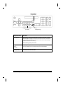
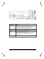
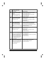
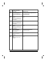
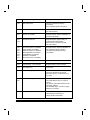
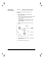
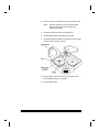
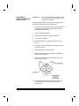
User's Reference
A-61003
Part Number 636985
September 1993
KODAK
IMAGELINK
™
Microimager 70,
Scanner 900,
Scanner 923,
Scanner/Microimager 990
OFFICE IMAGING
TABLE OF CONTENTS
Equipment Basics
• A description of the Operator Interface
• An operations checklist
• A maintenance checklist
• How to clear the document path
Function Codes
• How to use function codes
• Function code summary
• Function code listing
Operator Messages
• How to respond to operator messages
• Operator messages listing
Film Basics
• A description of the Film Cassette Status Display
• How to load film into a cassette
• How to load a cassette into the machine
• How to unload a partially exposed roll of film
• How to unload a fully exposed roll of film
A-61003
September 1993
i
EQUIPMENT BASICS
OPERATOR INTERFACE
Status Display
Film Mode Indicator
or
Scan Mode Indicator
Mode Name/Number
Lens Reduction
(if applicable)
Image Address
FFF.003.002.001
Mode 10
Document Level
Indicator
40X
Please wait...
Operator Message
Film Mode Indicators:
Simplex
Scan Mode Indicators:
Simplex
(one-sided; front)
Document Level Indicators:
Level 1
A-61003
September 1993
Duplex
Duo
Duplex
(two-sided; front and rear)
Level 2
Level 3
EB-1
Visual Tone Display
Up Arrow
Right Arrow
+
Film
Supply
Indicators
Plus Key
Down Arrow
Left Arrow
Keys/Indicators
Function
Visual Tone
Display
Both the upper and lower lights are illuminated any time an audio tone is
issued. When using a footswitch, the lower light is illuminated and an audio
tone is issued whenever the footswitch is pressed; while the upper light is
illuminated (but no audio tone is issued) when the footswitch is released.
Film Supply
Indicates how much film is available. A full cassette is represented by all lights
in the display; while an empty cassette is represented by no lights in the
display. The upper indicator represents the film supply in the upper cassette
while the lower indicator represents the film supply in the lower cassette.
Plus key
Used when inputting a value for the Image Address. When pressed,
it allows a field to remain unchanged.
Up Arrow
Used to increment values at a faster rate. Also used to increase a data value
when used with certain functions. Also used when entering an alpha character
in the Image Address Fixed Field.
Right Arrow
Used to increment values at a slower rate. Also used to display additional
messages in the Status Display. Also used when entering an alphanumeric
character in the Image Address.
Down Arrow
Used to decrement values at a faster rate. Also used to decrease a data value
when used with certain functions. Also used when entering an alpha character
in the Image Address Fixed Field.
Left Arrow
Used to decrement values at a slower rate. Also used to backspace, delete
the last keystroke, or clear messages in the Status Display. Also used when
entering an alphanumeric character in the Image Address.
EB-2
A-61003
September 1993
Film Advance
(if applicable)
P1 P2 P3 P4 P5
P6 P7 P8 P9 P10
Programmable Keys
(P Keys)
Jog
Transport Jog
Keys/Indicators
Function
Film Advance
When filming, used to advance film without making an exposure. Provides
blank film between images or at the end of a roll of film. Film is advanced as
long as the key is pressed (2.5 inches per second; or 0.5 inches if the key is
pressed for less than one second).
When scanning, this key is not used.
Programmable
Keys
(P Keys)
Used to perform specific functions. The P Keys have default values; any or
all of the defaults may be overridden/reprogrammed at installation.
Jog
Transport Jog
Used to momentarily turn on (jog) the transport system.
Used to help clear document jams.
A-61003
September 1993
EB-3
Numeric Keys
III
Level 3 Key
II
Level 2 Key
I
7
8
9
4
5
6
1
2
3
0
.
F
Level 1 Key
Decimal Key
Keys/Indicators
Function
Numeric Keys
(0 - 9)
Used to enter numeric data such as an Image Address or
Function Code.
F Key
Used to select one of the available functions, when used with the
numeric keys.
Decimal Key
Used to insert a field separator in an Image Address.
Level 1 Key
Used to identify the next document fed into the transport as a
Level 1 document.
Level 2 Key
Used to identify the next document fed into the transport as a
Level 2 document.
Level 3 Key
Used to identify the next document fed into the transport as a
Level 3 document.
EB-4
A-61003
September 1993
Clear/Cancel
Run
C
Next
NEXT
Key/Indicator
Enter
Function
Clear
Used to cancel a function without changing the preset values.
Used to clear the Status Display after executing select function codes.
Used to clear an operator message from the Status Display.
Run
Used to turn on the feeder and transport system.
NEXT
Used to enter the next document Image Address.
Stop
Used to stop the feeder and transport system.
Documents in the transport system when the Stop key is pressed will
be processed and placed in the exit hopper before the transport
system stops.
Enter
Used to enter data for a Function Code or an Image Address change.
A-61003
Stop
September 1993
EB-5
OPERATIONS CHECKLIST
Microimager 70
Setup:
√ Turn on main power switch, if necessary.
√ Turn on side panel switch.
√ Load film into cassette(s).
√ Load film cassette(s) into machine.
√ Select the lens holder position.
√ Select the mask.
√ Adjust the feed/separator rollers.
√ Adjust the feed shelf.
√ Adjust the feeder side guides.
√ Adjust the exit hopper side guides.
√ Adjust the exit hopper end stop.
√ Install the proper exit hopper deflector.
√ Perform an exposure step test, if necessary.
√ Prepare documents to feed into transport.
Running a Job:
√ Select an application mode.
√ Input any temporary/override operating values.
√ Enter or verify the starting Image Address.
√ Enter or verify the starting document image level.
√ Press the Run key.
√ Feed documents.
√ Press the Stop key.
√ Remove documents from the exit hopper.
√ Unload film cassette(s) from the machine.
√ Unload film from the cassette(s), if necessary.
√ Turn off side panel switch.
√ Turn off main power switch, if necessary.
EB-6
A-61003
September 1993
Scanner 900 or Scanner 923:
Setup:
√ Turn on main power switch, if necessary.
√ Turn on side panel switch.
√ Calibrate the machine.
√ Adjust the feed/separator rollers.
√ Adjust the feed shelf.
√ Adjust the feeder side guides.
√ Adjust the exit hopper side guides.
√ Adjust the exit hopper end stop.
√ Install the proper exit hopper deflector.
√ Prepare documents to feed into transport.
Running a Job:
√ Enable the machine from the host system.
√ Select an application mode.
√ Input any temporary/override operating values.
√ Enter or verify the starting Image Address.
√ Enter or verify the starting document image level.
√ Press the Run key.
√ Feed documents.
√ Press the Stop key.
√ Execute Scanner End-of-Job.
√ Remove documents from the exit hopper.
√ Turn off side panel switch.
√ Turn off main power switch, if necessary.
A-61003
September 1993
EB-7
Scanner/Microimager 990:
Setup:
√ Turn on main power switch, if necessary.
√ Turn on side panel switch.
√ Load film into cassette(s).
√ Load film cassette(s) into machine.
√ Select the lens holder position.
√ Select the mask.
√ Calibrate the machine.
√ Adjust the feed/separator rollers.
√ Adjust the feed shelf.
√ Adjust the feed shelf length.
√ Adjust the feeder side guides.
√ Adjust the exit hopper side guides.
√ Adjust the exit hopper end stop.
√ Install the proper exit hopper deflector.
√ Perform an exposure step test, if necessary.
√ Prepare documents to feed into transport.
Running a Job:
√ Enable the machine from the host system.
√ Select an application mode.
√ Input any temporary/override operating values.
√ Enter or verify the starting Image Address.
√ Enter or verify the starting document image level.
√ Press the Run key.
√ Feed documents.
√ Press the Stop key.
√ Execute Scanner End-of-Job.
√ Remove documents from the exit hopper.
√ Unload film cassette(s) from the machine.
√ Unload film from the cassette(s), if necessary.
√ Turn off side panel switch.
√ Turn off main power switch, if necessary.
EB-8
A-61003
September 1993
MAINTENANCE CHECKLIST
Daily maintenance:
√ Clean the accessories.
(DSA, Document Printer, etc.)
√ Clean the imaging guides.
Weekly maintenance:
√ Clean the cabinet.
√ Clean the feed and separator rollers.
√ Clean the mirrors, if applicable.
√ Vacuum inside the machine.
Monthly maintenance:
√ Check the air filter; replace if necessary.
√ Clean the film cassettes, if applicable.
A-61003
September 1993
EB-9
CLEARING THE
DOCUMENT PATH
There are six (6) areas in the transport system where
documents may become lodged:
A
B
C
D
E
F
The feeder/horizontal transport area
The imaging guide area
The lower roller assembly area
The vertical transport area
The upper turn area
The document exit area
• Check each transport area, in turn (Area A through
Area F), for documents lodged in the document path.
You only have to remove the jammed document(s).
The jog feature places the rest of the documents
in the exit hopper.
NOTE: Make certain that all operator accessible
areas (designated by green labels) are firmly
closed and all baffle plates are locked into
place.
• Press and hold down the JOG key to clear any
remaining documents.
• Collect the documents located in the transport
system. Put them back into their original order,
if necessary.
• Reset the Image Address, Level, etc., if necessary.
• Refeed the documents.
If an error code appears in the Status Display, check
each transport area again to make certain that all
documents have been cleared.
EB-10
A-61003
September 1993
FUNCTION CODES
USING FUNCTION CODES
There are a variety of functions available which may be
used to temporarily change operating conditions and
values, and to obtain system and accessory status
information.
To execute a function code:
• Press the F key.
• Press the numeric keys which correspond to the
desired function code.
• Press the Enter key.
Additional input may be necessary:
If the function is used to enable/disable an option (turn
an option on or off):
• Press the number one (1) key to turn the option ON;
or
Press the number zero (0) key to turn the option OFF.
• Press the Enter key.
If the function requires numeric input:
• Press the number key(s) required.
• Press the Enter key.
If the function is used to increment/decrement a
measurement:
• Press the up arrow key to increment the
measurement by one (1) inch (25 mm);
or
Press the down arrow key to decrement the
measurement by one (1) inch (25 mm);
or
Press the right arrow key to increment the
measurement by one-eighth (1/8) inch (3 mm);
or
Press the left arrow key to decrement the
measurement by one-eighth (1/8) inch (3 mm).
• Press the Enter key.
To cancel a function or clear the Status Display after
executing a function, press the Clear/Cancel key.
A-61003
September 1993
FC-1
FUNCTION CODE SUMMARY
Status
Accessory Status†
Date and Time Display†***
Elapsed Time†
Operation
F05
F23
F17
Counters
Level 0 Count†
Level 1 Count†
Level 2 Count†
Level 3 Count†
Total Document Count†
Reset Level Counts
F99
F06
F98
Filming*
F10
F11
F12
F13
F09
F14
Setup
Action/Confirmation Tone***
Alarm Tone***
Alarm Volume
Change Date***
Change Time***
Display Contrast
Display Language
Measurement System
Operator ID
Cassette ID Number*
Scanner Calibration**
Run
Terminate Batch†
Stop†
F93
F16
F15
F22
F21
F18
F19
F20
F34
F35
F37
Filming Only
Cassette ID Number
Roll Number
AEC On/Off
AEC Auto Adjust
AEC Fixed Adjust
Display Film Remaining†
Film Advance†
Film Leader†
Lead End Code
Trail End Code
Advance Film to End of Roll
F03
F35
F33
F24
F25
F26
F30
F27
F28
F31
F32
F29
Scanning**
Scanner Calibration
Latched Scanning Flag†
Momentary Scanning Flag†
Scanner End-of-Job
F37
F73
F74
F38
Mode
Select Mode
Select Linked Mode
Counting Only
Filming Only*
Restore Mode
F01
F91
F04
F03
F02
Index/Image Address
Last Image Address†
Level 0†
Level 1†
Level 2†
Level 3†
Fixed Field
Next Image Address
FC-2
F08
F07
F94
F95
F96
F92
F97
A-61003
September 1993
Bar Code***
Bar Code Reading On/Off
Partial Bar Code Reading On/Off
Bar Code Reading Confirmation Tone
Bar Code/Patch Reading Conf. Tone
Bar Code Test
Omit Bar Code Reading on Next Doc.†
OCR***
F60
F66
F63
F62
F65
F64
Document Controller
Length Checking On/Off
Omit Length Checking on Next Doc.†
Skew Detection
OCR On/Off
F76
Patch Reader
Patch Reader 1 On/Off
Patch Reader 2 On/Off***
End Fed Patch Reading On/Off***
Patch Reading Confirmation Tone***
Omit Patch Reading on Next Doc.†
F50
F51
F52
F53
F54
F70
F71
F72
Document Printers
All Document Printers On/Off
Primary Document Printer 1 On/Off
Secondary Doc Printer 1 On/Off***
Document Printer 12 On/Off
Omit Printing on Next Document†
Print Position
Print Test
Printer Character Shift
Printer Open Jet Test
Purge Frequency
Purge Print Head†
F40
F41
F42
F43
F44
F46
F45
F39
F56
F49
F48
Document Sorter***
Document Sorter On/Off
F80
Sort Next Doc. Only into Specified Bin† F81
Sort All Doc. into Specified Bin
F82
†
May be executed while transport is
running.
*
Available when filming; for use only with
Microimager 70 and
Scanner/Microimager 990.
**
Available when scanning; for use only with
Scanner 900, Scanner 923, and
Scanner/Microimager 990.
Endorser
Endorser On/Off
Endorser Mode
Endorser Print Position
F57
F58
F59
Footswitch
Footswitch Confirmation Tone***
A-61003
September 1993
F75
*** Available when using advanced capabilities;
for use only with Microimager 70 with
Advanced Function Module installed,
Scanner 900, Scanner 923, and
Scanner/Microimager 990.
FC-3
FUNCTION CODE LISTING
Code
Function Code Name/
Description
Additional Input
F01
Select Mode
Allows you select one of the
eighteen (18) application
modes.
• Enter the number of the application mode
you wish to select; one or two digits.
• Press the Enter key.
F02
Restore Mode
Allows you to restore the
current application mode to
its default status (as it was
defined at installation),
provided that mode overrides
are not saved.
none
F03
Filming Only
Allows you to film documents,
with no level counting,
endorsing, patch reading,
etc.
• Enter the number one (1) to turn
Filming Only ON; or
enter the number zero (0) to turn
Filming Only OFF.
• Press the Enter key.
F04
Counting Only
Allows you to count
documents only, with no
filming, scanning, etc.
• Enter the number one (1) to turn
Counting Only ON; or
enter the number zero (0) to turn
Counting Only OFF.
• Press the Enter key.
F05
Accessory Status
Allows you to display the
current status of each
accessory installed.
• Press the down arrow key to view the status
of the next accessory; or
press the up arrow key to view the status
of the previous accessory.
• Press the Clear key at any time to return to
a normal operating display.
F06
Terminate Batch
Allows you to prematurely
end a batch.
• Press the Clear key to return to a normal
operating display.
F07
Level 0
Allows you to assign Level 0
to the next document fed
into the transport.
none
FC-4
A-61003
September 1993
Code
Function Code Name/
Description
Additional Input
F08
Last Image Address
Allows you to display the
Image Address of the last
document processed.
• Press the Clear key to return to a normal
operating display.
F09
Total Document Count
Allows you to display the
total number of documents
processed. Also allows you
to reset the count to zero.
• Enter the number zero (0) to reset the counter.
• Press the Enter key.
Level 0 Count
Allows you to display the
total number of documents
assigned Level 0. Also allows
you to reset the count to zero.
• Enter the number zero (0) to reset the counter.
• Press the Enter key.
Level 1 Count
Allows you to display the
total number of documents
assigned Level 1. Also allows
you to reset the count to zero.
• Enter the number zero (0) to reset the counter.
• Press the Enter key.
Level 2 Count
Allows you to display the
total number of documents
assigned Level 2. Also allows
you to reset the count to zero.
• Enter the number zero (0) to reset the counter.
• Press the Enter key.
Level 3 Count
Allows you to display the
total number of documents
assigned Level 3. Also allows
you to reset the count to zero.
• Enter the number zero (0) to reset the counter.
• Press the Enter key.
Reset Level Counts
Allows you to reset all
counters (Level 0, Level 1,
Level 2, and Level 3).
• Press the Clear key to return to a normal
operating display.
F10
F11
F12
F13
F14
A-61003
September 1993
• Press the Clear key to return to a normal
operating display.
• Press the Clear key to return to a normal
operating display.
• Press the Clear key to return to a normal
operating display.
• Press the Clear key to return to a normal
operating display.
• Press the Clear key to return to a normal
operating display.
FC-5
Code
Function Code Name/
Description
Additional Input
F15
Alarm Volume
Allows you to adjust the
volume of the alarm.
• Press the up arrow key to increase the volume;
or press the down arrow key to decrease the
volume.
• Press the Enter key.
F16
Alarm Tone
Allows you to adjust the
pitch of the alarm tone.
• Press the up arrow key to increase the pitch;
or press the down arrow key to decrease the
pitch.
• Press the Enter key.
F17
Elapsed Time
Allows you to display the
number of hours the motor,
transport, and AC have been
running, in addition to the
non-resettable document
count.
• Press the right arrow key to view all four
time meters: Meter A shows the number of
motor-on hours; Meter B shows the number
of transport-on hours; Meter C shows the
number of AC-on hours; and Meter D shows
the non-resettable document count.
F18
Display Contrast
Allows you to adjust the
contrast of the Status Display.
• Press the up arrow key to increase the
contrast; or press the down arrow key to
decrease the contrast.
• Press the Enter key.
F19
Display Language
Allows you to choose the
language in which the Status
Display messages will appear.
• Press any arrow key to toggle between
the two available options.
• Press the Enter key.
F20
Measurement System
Allows you to choose the
measurement system in which
measurements are displayed.
• Press any arrow key to toggle between
the two available options.
• Press the Enter key.
F21
Change Time
Allows you to change the time.
• Enter the new time in the format illustrated.
• Press the Enter key.
F22
Change Date
Allows you to change the date.
• Enter the new date in the format illustrated.
• Press the Enter key.
F23
Time and Date Display
Allows you to view the
current time and date.
• Press the Clear key to return to a normal
operating display.
FC-6
A-61003
September 1993
Code
Function Code Name/
Description
Additional Input
F24
AEC On/Off
Allows you to turn the
Automatic Exposure Control
on or off.
• Enter the number one (1) to turn AEC ON; or
enter the number zero (0) to turn AEC OFF.
• Press the Enter key.
F25
AEC Auto Adjust
Allows you to adjust the AEC
exposure setting when the
AEC is in Auto Mode (ON).
• Press the left arrow key to decrease the
exposure level; or
press the right arrow key to increase the
exposure level.
• Press the Enter key.
F26
AEC Fixed Adjust
Allows you to adjust the AEC
exposure setting when the
AEC is in Fixed Mode (OFF).
• Press the left arrow key to decrease the
exposure level; or
press the right arrow key to increase the
exposure level.
• Press the Enter key.
F27
Film Advance
Allows you to advance the film
in six (6) inch [150 mm]
increments, or by a specific
amount input in inches or
millimeters.
• Enter the number of inches to advance the film,
the film by more or less than six (6) inches
[150 mm].
• Press the Enter key.
F28
Film Leader
Allows you to create a film
leader which is six (6) feet
[1.8 meters] of blank film.
none
F29
Advance Film to End of Roll
Allows you to advance the
film to the end of the roll.
none
F30
Display Film Remaining
Allows you to display the
amount of film remaining in
each film cassette.
• Press the Clear key to return to a normal
operating display.
A-61003
September 1993
FC-7
Code
Function Code Name/
Description
Additional Input
F31
Lead End Code
Allows you to create a lead
end code for retrieval
purposes.
• Enter the roll number, if different than the one
displayed.
• Press the Enter key.
• Enter the operator ID, if different than the one
displayed.
• Press the Enter key.
• Enter the next Image Address, if different than
the one displayed.
• Press the Enter key.
F32
Trail End Code
Allows you to create a trail
end code for retrieval
purposes.
none
F33
Roll Number
Allows you to display the
current roll number and/or
change to a new roll number.
To enter a new roll number:
• Enter a new roll number, up to nine (9) digits.
• Press the Enter key.
F34
Operator ID Number
Allows you to display the
current operator ID number
and/or change to a new
operator ID number.
To enter a new operator ID:
• Enter a new operator ID number, up to
three (3) digits.
• Press the Enter key.
F35
Cassette ID Number
Allows you to display the
current cassette ID number
and/or change to a new
cassette ID number.
To enter a new cassette ID number:
• Enter a new cassette ID number, up to
two (2) digits.
• Press the Enter key.
F37
Scanner Calibration
Allows you to initiate the
calibration process required
before scanning documents.
• Feed calibration target.
F38
Scanner End-of-Job
Allows you to signal the host
computer that the last
document of the job has been
fed into the transport.
none
FC-8
A-61003
September 1993
Code
Function Code Name/
Description
Additional Input
F39
Printer Character Shift
Allows you to select which
ink jets will be used to
print each character.
• Enter the number one (1) to select the leftmost
ink jets; or
enter the number two (2) to select the center
ink jets; or
enter the number three (3) to select the
rightmost ink jets.
• Press the Enter key.
F40
All Document Printers
On/Off
Allows you to turn all
document printers (primary
DP1, secondary DP1, and
DP12) on or off.
• Enter the number zero (0) to turn all document
printers OFF; or
enter the number one (1) to turn all document
printers ON.
• Press the Enter key.
F41
Primary DP1 On/Off
Allows you to turn the primary
document printer 1 on or off.
• Enter the number zero (0) to turn the primary
document printer 1 OFF; or
enter the number one (1) to turn the primary
document printer 1 ON.
• Press the Enter key.
F42
Secondary DP1 On/Off
Allows you to turn the
secondary document printer 1
on or off.
• Enter the number zero (0) to turn the secondary
document printer 1 OFF; or
enter the number one (1) to turn the secondary
document printer 1 ON.
• Press the Enter key.
F43
Document Printer 12 On/Off
Allows you to turn the
document printer 12 on or off.
• Enter the number zero (0) to turn the
document printer 12 OFF; or
enter the number one (1) to turn the
document printer 12 ON.
• Press the Enter key.
F44
Omit Printing on Next
Document Only
Allows you to omit printing by
all document printers on the
next document only.
• Enter the number one (1) to omit printing on the
next document; or
enter the number zero (0) to print on the next
document.
• Press the Enter key.
A-61003
September 1993
FC-9
Function Code Name/
Description
Additional Input
F45
Print Test
Allows you to test the position
and print quality of all
document printers installed.
• Enter the number of the print test you want
to perform: 1=Print IA test; 2=Prime test;
3=Shift test; or 4=standard test.
• Press the Enter key.
F46
Print Position
Allows you to specify how far
from the leading edge of the
document all document
printers will print.
• Press the up arrow key to increment the
starting print position by one (1) inch [25 mm];
or press the down arrow key to decrement the
starting print position by one (1) inch [25 mm];
or press the right arrow key to increment the
starting print position by one-eighth (0.125)
inch [3 mm]; or press the left arrow key to
decrement the starting print position by
one-eighth (0.125) inch [3 mm];
• Press the Enter key.
F48
Purge Print Head
Allows you to initiate an
immediate priming ink spurt.
none
F49
Purge Frequency
Allows you to specify how
often, in terms of the number
of documents fed into the
transport, a priming ink
spurt is initiated.
• Enter the number of documents, up to 50,000.
• Press the Enter key.
F50
Patch Reader 1 On/Off
Allows you to turn the primary
patch reader on or off.
• Enter the number zero (0) to turn the primary
patch reader OFF; or
enter the number one (1) to turn the primary
patch reader ON.
• Press the Enter key.
F51
Patch Reader 2 On/Off
Allows you to turn the
secondary patch reader
on or off.
• Enter the number zero (0) to turn the secondary
patch reader OFF; or
enter the number one (1) to turn the secondary
patch reader ON.
• Press the Enter key.
Code
FC-10
A-61003
September 1993
Code
Function Code Name/
Description
Additional Input
F52
End Fed Patch Reading
On/Off
Allows you to turn end fed
patch reading on or off.
• Enter the number zero (0) to turn end-fed
patch reading OFF; or
enter the number one (1) to turn end-fed
patch reading ON.
• Press the Enter key.
F53
Patch Reading Confirmation
Tone
Allows you to turn the patch
reading confirmation tone
on or off.
• Enter the number zero (0) to turn the
patch reading confirmation tone OFF; or
enter the number one (1) to turn the
patch reading confirmation tone ON.
• Press the Enter key.
F54
Omit Patch Reading on
Next Document Only
Allows you to omit patch
reading on the next document
only.
• Enter the number one (1) to omit patch reading
on the next document only; or
enter the number zero (0) to read patches
on the next document.
• Press the Enter key.
F56
Printer Open Jet Test
Allows you to determine
whether or not there are
non-functional ink jets in the
Document Printer 12 ink
cartridge.
• Press the Clear key to return to a normal
operating display.
F57
Endorser On/Off
Allows you to turn the
endorser on or off.
• Enter the number zero (0) to turn the
endorser OFF; or
enter the number one (1) to turn the
endorser ON.
• Press the Enter key.
F58
Endorser Mode
Allows you to display the
current endorser mode
and/or change the endorser
mode.
To change the endorser mode:
• Press any arrow key to toggle between the
two available options.
• Press the Enter key.
A-61003
September 1993
FC-11
Code
Function Code Name/
Description
Additional Input
F59
Endorser Print Position
Allows you to specify how far
from the leading edge of the
document the endorsement
will appear.
• Press the up arrow key to increment the
starting print position by one (1) inch [25 mm];
or press the down arrow key to decrement the
starting print position by one (1) inch [25 mm];
or press the right arrow key to increment the
starting print position by one-eighth (0.125)
inch [3 mm]; or press the left arrow key to
decrement the starting print position by
one-eighth (0.125) inch [3 mm];
• Press the Enter key.
F60
Bar Code Reading 1 On/Off
Allows you to turn bar code
reading on or off.
• Enter the number zero (0) to turn the bar code
reading OFF; or
enter the number one (1) to turn the bar code
reading ON.
• Press the Enter key.
F62
Bar Code / Patch Reading
Confirmation Tone
Allows you to turn the bar
code/patch reading
confirmation tone on or off.
• Enter the number zero (0) to turn the bar code/
patch reading confirmation tone OFF; or
enter the number one (1) to turn the bar code/
patch reading confirmation tone ON.
• Press the Enter key.
F63
Bar Code Reading
Confirmation Tone
Allows you to turn the bar
code reading confirmation
tone on or off.
• Enter the number zero (0) to turn the bar code
reading confirmation tone OFF; or
enter the number one (1) to turn the bar code
reading confirmation tone ON.
• Press the Enter key.
F64
Omit Bar Code Reading on
Next Document Only
Allows you to omit bar code
reading on the next document
only.
• Enter the number one (1) to omit bar code
reading on the next document only; or
enter the number zero (0) to read bar codes
on the next document.
• Press the Enter key.
F65
Bar Code Test
Allows you to perform a test
to verify the operation of
the bar code reader.
• Enter the number of the bar code test you want
to perform: 1=Evaluate; 2=Display;
3=%Kodak; or 4=%Norm.
• Press the Enter key.
FC-12
A-61003
September 1993
Code
Function Code Name/
Description
Additional Input
F66
Partial Bar Code Reading
On/Off
Allows you to turn partial
bar code reading on or off.
• Enter the number zero (0) to turn partial
bar code reading OFF; or
enter the number one (1) to turn partial
bar code reading ON.
• Press the Enter key.
F70
Length Checking On/Off
Allows you to turn length
checking on or off.
• Enter the number one (1) to turn length
checking ON; or
enter the number zero (0) to turn length
checking OFF.
• Press the Enter key.
F71
Omit Length Checking
On Next Document Only
Allows you to omit length
checking on the next document
only.
• Enter the number one (1) to omit length
checking on the next document only; or
enter the number zero (0) to perform length
checking on the next document.
• Press the Enter key.
F72
Skew Detection
Allows you to turn skew
detection on or off.
• Enter the number one (1) to turn skew
detection ON; or
enter the number zero (0) to turn skew
detection OFF.
• Press the Enter key.
F73
Latched Scanning Flag
Allows you to set a flag which
alerts the host system that the
document, and those which
follow, are of special interest.
The flag will remain activated
for every document until
it is turned off.
• Enter the number one (1) to turn the latched
scanning flag ON; or
enter the number zero (0) to turn the latched
scanning flag OFF.
• Press the Enter key.
F74
Momentary Scanning Flag
Allows you to set a flag which
alerts the host system that the
next document only is of
special interest.
• Enter the number one (1) to turn the
momentary scanning flag ON.
• Press the Enter key.
A-61003
September 1993
FC-13
Function Code Name/
Description
Additional Input
F75
Footswitch Confirmation
Tone
Allows you to turn the
footswitch confirmation tone
on or off.
• Enter the number zero (0) to turn the
footswitch confirmation tone OFF; or
enter the number one (1) to turn the
footswitch confirmation tone ON.
• Press the Enter key.
F76
OCR On/Off
Allows you to turn OCR
on or off.
• Enter the number one (1) to turn OCR ON; or
enter the number zero (0) to turn OCR OFF.
• Press the Enter key.
F80
Document Sorter On/Off
• Enter the number one (1) to turn Document
Sorter ON; or enter the number zero (0) to turn
Document Sorter OFF.
• Press the Enter key.
F81
Sort Next Document Only
to Specified Bin
• Press the up/down arrow key to view/select bin
options.
• Press the Enter key.
F82
Sort All Documents to
to Specified Bin
• Press the up/down arrow key to view/select bin
options.
• Press the Enter key.
F91
Select Linked Mode
Allows you to switch from
one application mode to
another, keeping the last
Image Address.
• Enter the number of the application mode
you wish to select; one or two digits.
• Press the Enter key.
F92
Fixed Field
Allows you to enter a new
fixed field value, containing
alphanumeric characters.
To enter a numeric character:
• Enter the number(s) to be placed in the Fixed
Field.
• Press the Enter key.
Code
To enter an alphabetic character:
• Press the up or down arrow key.
• Press the left or right arrow key to position
the highlighted cursor over the character to
be placed in the Fixed Field.
• Press the Enter key.
FC-14
A-61003
September 1993
Code
Function Code Name/
Description
Additional Input
F93
Action/Confirmation Tone
Allows you to adjust the
pitch of the action/confirmation
tone.
• Press any arrow key to toggle between the
two available options.
• Press the Enter key.
F94
Level 1
Allows you to assign Level 1
to the next document fed into
the transport.
none
F95
Level 2
Allows you to assign Level 2
to the next document fed into
the transport.
none
F96
Level 3
Allows you to assign Level 3
to the next document fed into
the transport.
none
F97
Next Image Address
Allows you to input the next
Image Address.
• Enter the next Image Address.
• Press the Enter key.
F98
Stop
Allows you to stop the
transport.
none
F99
Run
Allows you to turn on the
transport.
none
A-61003
September 1993
FC-15
OPERATOR MESSAGES
If a message appears in the Status Display which is within the
ranges E000-E299 or E500-E599, you should take the action
indicated in the table(s) which appear in this section.
Users
IMPORTANT: Never power down the machine without first
contacting your System Administrator.
If a message appears in the Status Display which is within the
ranges E300-E499 or E600-E999, you should contact your
System Administrator.
System Administrators
If a message appears in the Status Display which is within the
ranges E300-E499 or E600-E999, you should be contacted by
the operator.
The following action(s) should be taken:
• Determine whether or not the error can be addressed from the host
system, if applicable.
• Attempt to clear the error by taking the action indicated in the
table(s) which appear in this section.
• If the prescribed action(s) do not clear the error, initiate a controlled
power-downsequence:
- Wait for all information currently held in the buffer to be transferred
to the host system, if applicable.
- Turn off the Scanner/Microimager transport using the side panel
switch.
- Turn off the Scanner/Microimager power using the main power
switch.
- Wait 10 - 30 seconds.
- Turn on the Scanner/Microimager power using the main power
switch.
- Turn on the Scanner/Microimager transport using the side panel
switch.
• If the error condition is not cleared using the controlled power-down
sequence, contact service.
A-61003
September 1993
OM-1
OPERATOR MESSAGE
LISTING
Code
Operator Message Displayed
Description/Action Required
E000
Memory battery low - call service
Call service - do not turn off the machine.
E100
Please wait
No action required.
Wait for the message to clear.
E101
Auto shut off, press RUN
Press the Run key to continue.
Feed documents.
E102
Press STOP and try again
Press the Stop key and try again.
E103
Select valid mode
Invalid mode selected.
Enter function code F01 to select another
mode.
E104
Function not available
Invalid function code entered.
Enter another function code.
E105
Low film warning
Low film in cassette(s).
Enter function code F30 to determine how
much film remains.
Press the Run key to continue filming, or
begin filming on a new roll.
E106
Warning - document length error
Check the document length to see if it is
shorter than the minimum or longer than
the maximum allowed.
Refeed the document.
E107
Warning - skewed document
Refeed the document.
E108
Low battery warning - upper cass
Replace upper cassette battery.
E109
Low battery warning - lower cass
Replace lower cassette battery.
E110
Upper lamp warning, press RUN
Press the Run key to continue.
Change the lamps when the current set of
documents has been processed.
E111
Lower lamp warning, press RUN
Press the Run key to continue.
Change the lamps when the current set of
documents has been processed.
OM-2
A-61003
September 1993
Code
Operator Message Displayed
Description/Action Required
E112
Invalid patch level
Invalid patch was used.
Feed correct patch.
E113
Enter correct Image Address
Use the NEXT key to enter correct Image
Address.
E114
Check current level
Check the current document image level.
Conflicting input regarding the proper level
was received.
E115
Verify correct cassettes
Verify that both cassettes are to be used
together before proceeding with filming
mode setup.
E117
E118
E119
Enter correct level/Image Address
Document image level assignment and
next Image Address input conflict.
Specify another document image level, or
use the NEXT key to enter a valid Image
Address.
E120
Diagnostic running - do not use
Please do not use; the machine is being
serviced.
E121
E122
Check front patch reader
Check rear patch reader
Patch code not recognized.
Verify that the patch document was fed
into the transport in the proper orientation.
If not, refeed the patch document.
If so, change to a non-patch mode to
continue. Call service.
E123
Command data rejected - resend
Command not recognized.
Enter command again.
E124
E125
Command not allowed in this model
Command cannot be performed.
Enter a valid command.
E126
Enter correct command
Press correct key(s) for mode selected.
E127
Feeder waiting for host system
System is busy. No action required.
Wait for message to clear.
E128
Feeder adjustment warning
Check and adjust feed and separator
roller gap.
A-61003
September 1993
OM-3
Code
Operator Message Displayed
Description/Action Required
E129
Dirty AEC sensor
Perform maintenance/cleaning
procedures.
If the message repeats, call service.
E130
OCR not installed
Requested action requires installation of
the OCR accessory.
E131
Device not enabled
Requested action requires installation of
the Bar Code Reader.
E132
E133
Enable barcode first
Requested action requires that you
enable the Bar Code Reader.
Enter function code F60 to enable
bar code reading.
E140
E141
E142
E143
E144
E145
E146
Document Printer not installed
Patch Reader not installed
Detection System not installed
Barcode Reader not installed
Image Marker not installed
Endorser not installed
Document Sorter not installed
Requested action required installation of
the module/accessory indicated.
The required module/accessory is
not installed.
E158
Check battery - upper cassette
Replace battery in upper cassette.
E159
Check battery - lower cassette
Replace battery in lower cassette.
E170
Film writer error
Call service.
E190
Sorter in improper position
The Sorter was not able to or did not
access the specified or proper bin.
Press the Jog key. Press the Run key.
Try again.
E200
E201
Verify/enter Image Address
An error has occurred in the system and
the Image Address may no longer be
correct.
Use function code F08 to determine the
last Image Address.
Use the NEXT key to correct the Image
Address, if necessary.
E202
Change film mode or cassette(s)
Replace the cassette(s) with one(s) that
match the film mode setup, or
change the film mode setup.
OM-4
A-61003
September 1993
Code
Operator Message Displayed
Description/Action Required
E203
Cassette info does not match
Use the NEXT key to enter the correct
Image Address, or
change cassette(s).
E204
Skewed document - refeed
Press the Clear key.
Use the NEXT key to enter the correct
Image Address and refeed
document(s).
E205
Level overflow - press next level
Press the Clear key.
Use the NEXT key to enter the correct
Image Address, or
press a level key for a higher level.
E206
Check print head
Install the correct Document Printer
print head.
E207
Check printer installation
Document Printer not correctly installed.
Properly install the Document Printer
print head.
E208
E209
Change DSA lamp
Replace the DSA lamp.
E210
Approaching end of film
Enter function code F30 to determine the
amount of film remaining.
Press RUN to continue filming, or
begin filming on a new roll.
E211
Enter correct Image Address
Use the NEXT key to enter correct Image
Address.
E212
End of side 1, flip cassette
Turn cassette over, and
reinsert in the proper orientation.
Press the Run key to continue.
E213
End of side 2, start trail code
Enter function code F32 to generate
trail end code.
E214
Document length error - refeed
Press the Clear key.
Use the NEXT key to enter the correct
Image Address and refeed document(s).
E215
No image mark - Refeed by hand
Select a document image level.
Press the Run key and refeed
document(s).
A-61003
September 1993
OM-5
Code
Operator Message Displayed
Description/Action Required
E216
Sorter failed to move to hopper
The Sorter was not able to or did not
access the specified or proper bin.
Press the Jog key. Press the Run key.
Try again.
E217
Sort bin conflict
Sorting criteria and slected bin do not
correspond. Use Function Code F81 or
F82 to select another bin. Try again.
E219
Clear error and refeed last doc
Press the Clear key. Press the Run key
and refeed the last document.
E220
Check for jam in entrance transp
Clear the document path.
Press the Clear key. Press the Jog key.
Press the Run key and refeed
document(s).
E221
Clean entrance sensor
Perform maintenance/cleaning
procedures.
E225
Check for jam in transport
Clear the document path.
Press the Clear key. Press the Jog key.
Press the Run key and refeed
document(s).
E226
Clean slide-out sensor reflector
Perform maintenance/cleaning
procedures.
E227
Check for jam in transport
Clear the document path.
Press the Clear key. Press the Jog key.
Press the Run key and refeed
document(s).
E228
Check for jam in upper transport
Clear the document path.
Press the Clear key. Press the Jog key.
Press the Run key and refeed
document(s).
E229
Clean exit sensor
Perform maintenance/cleaning
procedures.
E230
Open access door to correct error
Open the access door.
Verify that all operator accessible areas
are properly closed.
Press the Run key to continue.
OM-6
A-61003
September 1993
Code
Operator Message Displayed
Description/Action Required
E231
Press JOG, and try again
Press the Jog key. Press the Run key.
Try again.
E232
Close all access doors and RUN
Close all access doors.
Press the Run key to continue.
E233
Close cassette access door
Close the cassette access door.
Press the Run key to continue.
E234
Press JOG, and try again
Press the Jog key. Press the Run key.
Try again.
E235
E236
Turn main power OFF and ON
Turn the side panel switch off.
Turn the main power switch off.
Wait five (5) to ten (10) seconds.
Turn the main power switch on.
Turn the side panel switch on.
If the error repeats, call service.
E237
Open and close cass access door
Open and close the cassette access door.
Press the Run key to continue.
E238
User function string invalid
The P-Key, End-of-Batch, etc. definition
made during installation is invalid.
Correct the definition using the Mode
Setup Software.
E240
E241
E242
E243
E244
E245
Enter correct level of IA - refeed
Set or change the document image level
or use the Next key to enter a new Image
Address.
Press the Run key to continue.
E246
Conflicting input - what level?
Set or change the document image level
to confirm the proper document image
level.
Press the Run key to continue.
E249
Select duo or change cassettes
Complete the proper setup for duo mode
or change cassette(s).
E250
Use other side of upper cassette
Rotate the film cassette to film on the
proper side.
Reload the film cassette into the machine.
A-61003
September 1993
OM-7
Code
Operator Message Displayed
Description/Action Required
E251
Use other side of lower cassette
Rotate the film cassette to film on the
proper side.
Reload the film cassette into the machine.
E252
Check film threading - both cass
Check film threading in the cassettes.
Press the Clear key.
Press the Run key to continue.
E253
Check film threading - upper cass
Check film threading in the cassette.
Press the Clear key.
Press the Run key to continue.
E254
Check film threading - lower cass
Check film threading in the cassette.
Press the Clear key.
Press the Run key to continue.
E257
AEC error - press STOP, then RUN
Exposure error.
Press the Stop key.
Press the Run key and refeed the
document(s).
E258
Replace battery - upper cassette
Replace the upper cassette battery.
E259
Replace battery - lower cassette
Replace the lower cassette battery.
E260
Check cassette insertion
Verify that the cassette(s) are in the
proper position and are properly inserted.
Press the Run key to continue.
E261
Check upper exposure lamps
Replace upper exposure lamps.
E262
Check lower exposure lamps
Replace lower exposure lamps.
E263
Check film threading - upper cass
Check film threading in the upper
cassette.
Press the Clear key.
Press the Run key to continue.
E264
Check film threading - lower cass
Check film threading in the lower
cassette.
Press the Clear key.
Press the Run key to continue.
E265
Clear error, re-enter lead code
Press the Clear key.
Enter function code F31 to generate
lead end code.
OM-8
A-61003
September 1993
Code
Operator Message Displayed
Description/Action Required
E266
Clear error, re-enter trail code
Press the Clear key.
Enter function code F32 to generate
trail end code.
E267
Clear error, re-enter IA
Press the Clear key.
Use the NEXT key to enter an Image
Address.
Press the Run key to continue.
E268
Clear error, advance film
Press the Clear key.
Enter function code F27 to advance film.
Press the Run key to continue.
E269
Use cassette side 1
Insert the film cassette so that side 1
will be exposed.
E270
Use cassette side 2
Insert the film cassette so that side 2
will be exposed.
E271
Wrong lens for film mode
Change the lens reduction to match the
film mode selected, or
change the application mode to one
where the specified film mode and the
lens reduction selected are compatible.
E272
Select proper mask for film mode
Select the proper mask for the film mode
selected, or
change the application mode to one
where the specified film mode and the
mask selected are compatible.
E275
Select proper lens for this mode
Select the proper lens reduction for the
film mode selected, or
change the application mode to one
where the specified film mode and the
lens reduction selected are compatible.
E276
Check lens turret seating
Rotate the lens turret so that it is locked
in place.
E280
Feeder off due to host request
System is busy.
Feeder will be reactivated when the
system is no longer busy.
Wait until the message clears and
continue.
A-61003
September 1993
OM-9
Code
Operator Message Displayed
Description/Action Required
E281
OCR was reset - restart batch
Use the NEXT key to enter a starting
Image Address.
Rerun the batch.
E282
Comm buffer full - please wait
System is busy.
Wait until the message clears and
continue.
E283
Invalid configuration for OCR
OCR is not enabled in the mode selected.
Enable the OCR using function code
F76, or
change the application mode to one
in which the OCR is enabled.
E284
OCR initializing - please wait
System is busy.
Wait until the message clears and
continue.
E285
Feeder off due to OCR request
System is busy.
Feeder will be reactivated when the
system is no longer busy.
Wait until the message clears and
continue.
E286
Feed calibration target
Calibration process has started.
Press the Run key and feed the
calibration target into the transport.
E287
Feeder waiting for AEC
Turn the side panel switch off.
Turn the main power switch off.
Wait five (5) to ten (10) seconds.
Turn the main power switch on.
Turn the side panel switch on.
If the error repeats, call service.
E288
OCR batch stopped due to error
Determine the cause of the error
via the OCR Workstation interface.
Correct the error. Rerun the batch.
E291
Scanner disabled
The machine has been disabled due to
an error.
Determine the cause of the error
via the host system.
Enable the machine.
Press the Run key to continue.
OM-10
A-61003
September 1993
Code
Operator Message Displayed
Description/Action Required
E292
Lamp failure
Replace the exposure lamps.
Recalibrate the machine.
E293
Host recovery required
Contact your System Administrator to
initiate the required action on the
host system.
E294
Front calibration warning
Perform maintenance/cleaning
procedures for the Document Scanning
Array, Image Guides, etc.
Check the lamps; replace if necessary.
Recalibrate the machine.
E295
Rear calibration warning
Perform maintenance/cleaning
procedures for the Document Scanning
Array, Image Guides, etc.
Check the lamps; replace if necessary.
Recalibrate the machine.
E296
Target not seen
Repeat the calibration process using
a blank target.
If error repeats, call service.
E297
Document que full
The feeder and transport are stopped,
and the machine is disabled.
Transfer images from the image buffer to
the host system.
Re-enable the machine.
Press the Run key to continue.
E298
Calibration required
Enter function code F37 to initiate the
calibration sequence.
E500
E501
E502
E503
E512
E513
E550
E551
E552
E553
E562
E563
System error
Contact your System Administrator.
A controlled power-down sequence
is required.
A-61003
September 1993
OM-11
Code
Operator Message Displayed
Description/Action Required
E504
E505
E506
E507
E508
E509
E510
E511
E514
E515
E516
Display communications error
Press the Jog key to clear all documents
from the transport.
Press the Run key and refeed the
document(s).
E554
E555
E556
E557
E558
E559
E560
E561
COIN-2 communications error
Check cable connections.
Verify that all equipment components
are powered on.
E600
through
E699
various messages
Turn the side panel switch off.
Turn the main power switch off.
Wait five (5) to ten (10) seconds.
Turn the main power switch on.
Turn the side panel switch on.
If the error repeats, or if additional
errors are received, call service.
E700
through
E799
various messages
Turn the side panel switch off.
Turn the main power switch off.
Wait five (5) to ten (10) seconds.
Turn the main power switch on.
Turn the side panel switch on.
If the error repeats, or if additional
errors are received, call service.
E564
E555
E556
OM-12
A-61003
September 1993
Code
Operator Message Displayed
Description/Action Required
E800
through
E899
various messages
Turn the side panel switch off.
Turn the main power switch off.
Wait five (5) to ten (10) seconds.
Turn the main power switch on.
Turn the side panel switch on.
If the error repeats, or if additional
errors are received, call service.
E900
through
E999
various messages
Turn the side panel switch off.
Turn the main power switch off.
Wait five (5) to ten (10) seconds.
Turn the main power switch on.
Turn the side panel switch on.
If the error repeats, or if additional
errors are received, call service.
A-61003
September 1993
OM-13
FILM BASICS
FILM CASSETTE
STATUS DISPLAY
Each film cassette contains a window which displays graphic
symbols representing film/cassette status conditions:
Cassette ID Number - a number assigned by the operator.
Film Indicator - indicates whether or not a spool of film is
properly loaded into the cassette.
Film Supply Gauge - using a series of ten (10) bars, the gauge
indicates the amount of film remaining in the cassette. When all
bars are shown, the cassette is full. When no bars are shown,
the cassette is empty. When a striped pattern is shown, a new
roll of film has been loaded into the cassette, but the cassette
has not been inserted into the machine.
Low Battery - indicates whether or not the battery needs to be
replaced. Replace with a fresh battery immediately to avoid
losing display information.
Side Two Symbol - the side two symbol appears only when
filming in duo mode and the cassette is to be reinserted for
filming on the second side.
A-61003
September 1993
FB-1
LOADING FILM
INTO A CASSETTE
IMPORTANT:
Always load and unload film in subdued,
indirect light to help prevent "fogging".
The following steps are required to load film into the
cassette(s):
FB-2
1.
Select the correct film for your application(s) and
appropriate cassette(s).
2.
Check the cassette display before loading a new roll of film:
• Verify that the film supply indicator shows that the
cassette is empty.
• Verify that there is not a low battery symbol. If a low
battery symbol appears, or the display is not visible,
replace the battery.
3.
Place the cassette on a flat surface, with the top cover
side up.
4.
Press down on the cover latch and turn counterclockwise
to unlock the top cover.
5.
Remove the top cover and set it aside.
A-61003
September 1993
6.
Open a new box of microfilm and remove the spool of film.
NOTE: Save the empty box to store the exposed film
prior to processing and for storing the film
following processing.
7.
Peel off the paper band from around the spool.
8.
Unwind approximately 18 inches (46 cm) of film.
9.
Lift the light guard and place the spool of film on the supply
spindle, with the number 1 side up.
10. Slowly rotate the spool until the two round holes on the
spool engage the lugs on the spindle.
11. Lower the light guard.
A-61003
September 1993
FB-3
12. Thread the film around the guide roller, drive roller, and
idler roller, following the path indicated by the threading
arrows inside the film cassette.
13. Fold back approximately 1/2 inch (1 cm) at the end of the
film.
14. Pick up the take-up spool and hold it with the number 1
side up.
15. Insert the folded end of the film into the slot in the take-up
spool core.
16. Rotate the spool counterclockwise to secure the film on the
spool.
FB-4
A-61003
September 1993
17. Place the take-up spool over the take-up spindle lugs.
18. Slide the release lever toward the battery compartment and
hold it in this position.
19. Slowly rotate the take-up spool couterclockwise three
complete turns to secure the film onto the spool. Allow the
release lever to return to its normal position.
20. Replace the top cover on the cassette. Press down on the
cover latch and turn it clockwise to lock the top cover in
place.
NOTE: If the film has been properly loaded, the film supply
indicator will now change to show that the cassette is
full.
A-61003
September 1993
FB-5
LOADING
CASSETTE(S) INTO
THE MACHINE
A film cassette can be loaded into either the upper or lower film
slot.
1.
Open the cassette access door.
2.
Swing the drive release lever (green handle) out.
3.
Insert film cassette(s).
NOTE: Refer to the label on the inside of the cassette access
door for cassette orientation. The display on the film
cassette is oriented differently depending upon the film
slot being used.
4.
Swing the drive release lever back into place.
5.
Close the cassette access door.
Whenever a fresh or partial roll of film is loaded into the
machine, a leader is automatically made when the cassette
access door is closed and the side panel switch has been
turned on.
A Please Wait... message will appear in the Status Display
while the film leader is being advanced. Once a normal
operating display appears, indicating that the leader has been
advanced, check the film supply indicators on the control panel
to determine if you have enough film to complete the job.
FB-6
A-61003
September 1993
UNLOADING A
PARTIALLY EXPOSED
ROLL OF FILM
IMPORTANT:
Do not unload a partially exposed roll of film
when using duo mode. Images will be lost if
a partial roll is unloaded.
It is assumed that all documents have been deposited in the
exit hopper and the Stop key has been pressed.
1.
Enter function code F28 Film Leader. This will result in six
(6) feet of film being advanced onto the take-up spool,
protecting the filmed images.
2.
Open the cassette access door.
3.
Swing the drive release lever (green handle) out.
4.
Remove film cassette(s).
5.
Place the cassette on a flat surface, with the top cover
side up.
6.
Press down on the cover latch and turn counterclockwise
to unlock the cover.
7.
Remove the top cover and set it aside.
8.
Slide the release lever toward the battery compartment
and hold it in this position.
9.
Place a finger over the take-up spool flange to prevent
the film from unwinding.
10. Cut the film with a pair of scissors; cut where indicated
in the illustration (between the idler roller and the
take-up spool).
A-61003
September 1993
FB-7
11. Lift the take-up spool out of the cassette.
12. Place the spool into the film box. Allow approximately
2 to 3 inches (5 to 8 cm) of the film to protrude from under
the lid of the box. Close the top of the box securely.
13. Write identification data (i.e., subject,. title, date, job
number, etc.) on the film box label. The film is now ready
for processing.
To continue filming using the unexposed portion of the roll of
film:
14. Obtain an empty take-up spool.
15. Unwind approximately 18 inches (46 cm) of film.
16. Fold back approximately 1/2 inch (1 cm) at the end of the
film.
17. Pick up the take-up spool and hold it with the number 1
side up.
18. Insert the folded end of the film into the slot in the take-up
spool core.
19. Rotate the spool counterclockwise to secure the film on the
spool.
20. Place the take-up spool over the take-up spindle lugs.
21. Slide the release lever toward the battery compartment and
hold it in this position.
22. Slowly rotate the take-up spool counterclockwise three full
turns to secure the film on the spool. Allow the release
lever to return to its normal position.
23. Replace the top cover on the cassette. Press down on the
cover latch and turn it clockwise to lock the cover in place.
NOTE: The cassette may now be inserted into the machine
and filming may continue.
FB-8
A-61003
September 1993
UNLOADING A FULLY
EXPOSED ROLL OF
FILM
Use the following steps to unload a fully exposed roll of film
(simplex, duplex, or duo format):
It is assumed that all documents have been deposited in the
exit hopper and the Stop key has been pressed.
1.
Enter function code F29 Advance Film to End of Roll.
This will result in the entire length of the film being
advanced onto the take-up spool.
2.
Open the cassette access door.
3.
Swing the drive release lever (green handle) out.
4.
Remove film cassette(s).
5.
Place the cassette on a flat surface, with the top cover
side up.
6.
Press down on the cover latch and turn counterclockwise
to unlock the cover.
7.
Remove the top cover and set it aside.
8.
Place a finger over the take-up spool flange to prevent the
film from unwinding and lift up to remove the spool of film.
9.
Place the spool into the film box. Allow approximately
2 to 3 inches (5 to 8 cm) of the film to protrude from under
the lid of the box. Close the top of the box securely.
10. Write identification data (i.e., subject, title, date, job
number, etc.) on the film box label. The film is now ready
for processing.
NOTE: Replace the top cover back on the cassette(s),
regardless of whether or not you immediately reload
the cassette. This will help extend battery life.
A-61003
September 1993
FB-9
PROGRAMMABLE KEYS
P1 P2 P3 P4 P5
P6 P7 P8 P9 P10
Programmable Keys
(P Keys)
P-key
P1
P2
P3
P4
P5
P6
P7
P8
P9
P10
Function(s)
APPLICATION MODES
Mode
Number
1
2
3
4
5
6
7
8
9
10
11
12
13
14
15
16
17
18
Mode
Name
Application(s)
Office Imaging
EASTMAN KODAK COMPANY
Rochester, New York 14650
Kodak and Imagelink are trademarks.
The new vision of Kodak
A-61003
9/93
©Eastman Kodak Company, 1993 Printed in U.S.A.