1
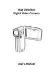
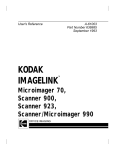
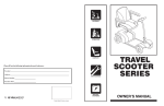
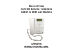
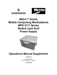
DETECTO-PAK 4®
Users Manual
Proprietary Notice
The contents of this manual are proprietary to Heath Consultants
Incorporated. Reproduction of this manual, in whole or in part, is
prohibited without the express written consent of Heath Consultants
Incorporated.
Heath Consultants Incorporated operates under a continual product
improvement program and reserves the right to make improvements
and/or changes without prior notification.
This manual supersedes all previous manuals for the Heath
Detecto-Pak 4.
HPN Manual: 100786-0 Rev D
HPN DP 4 Complete Unit: 100659-0
©COPYRIGHT 1995, Heath Consultants Incorporated
Detecto-Pak® 4
Users Manual
Heath Consultants Incorporated
Houston, TX
713-844-1300
Fax: 713-844-1309
1-800-HEATH-US
www.heathus.com
Safety, Leadership, Innovation, Performance
Then, Now and Tomorrow
TABLE OF CONTENTS
INTRODUCTION ……..............................…………………………………. .ii
FUNCTION ….............................…………………………………………… iii
WARNINGS ...........................................……………………………………. .iv
CHAPTER ONE
PROCEDURES
I. DETECTO-PAK 4 PROCEDURES…………........................……… 1
CHAPTER TWO
FUEL CYLINDERS
II. FUEL MOTHER TANKS, FUEL CYLINDERS …......................…. 6
CHAPTER THREE
CALIBRATION CYLINDERS
III. CALIBRATION MOTHER TANKS, CALIBRATION
CYLINDERS …....................................................................................... 10
CHAPTER FOUR
NiMH BATTERY
IV. NICKEL METAL HYDRIDE (NiMH) BATTERY ………..............…. 13
CHAPTER FIVE
OPERATION
V. OPERATING THE DETECTO-PAK 4 ….........................…………… 16
CHAPTER SIX
CALIBRATION
VI.CALIBRATION …….............................……………………………….. 23
CHAPTER SEVEN
APPLICATIONS
VII. APPLICATIONS FOR THE DETECTO-PAK 4 ………...........…… 28
CHAPTER EIGHT
MAINTENANCE
VIII. MAINTENANCEINFORMATION …………....……………………. 30
CHAPTER NINE
SERVICE INFORMATION
IX. SERVICE INFORMATION ……………………………………......... I
GLOSSARY ……………………………………………………………… IV
INDEX ……………………………….………………………………..….. VI
i
INTRODUCTION
The HEATH Detecto-Pak 4 Flame Ionization Hydrocarbon Detector
is designed to withstand normal field use and provide sensitive
indication of the presence of hydrocarbon vapors.
This instruction manual is divided into nine chapters. Each chapter
is designed to assure that the operator will obtain the best use of
the Detecto-Pak 4. Chapter One, Detecto-Pak 4 features, should be
required reading for all operating personnel prior to using the DetectoPak 4. Chapter Five, Operating the Detecto-Pak 4, outlines the steps
necessary to make the instrument operational. Other chapters cover
topics such as troubleshooting procedures, periodic maintenance,
applications, etc.
ii
FUNCTION
The Heath Detecto-Pak 4 Flame Ionization Hydrocarbon Detector
is designed to detect and measure the presence of hydrocarbons
(calibrated for methane). The instrument has five sensitivity ranges:
10, 50, 100, 1,000 (1K), and 10,000 (10K) ppm (1% gas).
This instruction manual describes the operation of the instrument and
provides limited maintenance information. Heath firmly believes the
Detecto-Pak 4, when properly maintained, will provide reliability and
ease of operation for many years.
iii
WARNING
EXPLOSIVE GAS MIXTURES CAN CAUSE SERIOUS INJURY
OR DEATH. INHALATION OF VAPORS CAN CAUSE HEALTH
IMPAIRMENT.
WARNING
IT IS ESSENTIAL THAT USERS OF THIS INSTRUMENT READ,
UNDERSTAND, AND FOLLOW THE INSTRUCTIONS FOR
OPERATION AND MAINTENANCE AND THE PRECAUTIONS
CONTAINED IN THIS MANUAL TO ENSURE THE
INSTRUMENT IS USED IN A PROPER AND SAFE MANNER.
WARNING
DO NOT ATTEMPT TO REPAIR THE INTERNAL FUEL
REGULATOR. DISASSEMBLY COULD CAUSE DAMAGE TO
THE DETECTO-PAK 4.
WARNING
DO NOT ATTEMPT TO REPAIR THE FUEL OR CALIBRATION
CYLINDER/VALVE ASSEMBLY.
WARNING
THE BATTERY MUST BE CHANGED OR CHARGED IN AN
AREA KNOWN TO BE NONFLAMMABLE TO REDUCE THE
RISK OF IGNITING A FLAMMABLE ATMOSPHERE.
WARNING
iv
CHAPTER ONE
I. DETECTO-PAK 4 FEATURES
This Chapter describes the features of the Detecto-Pak 4. Please refer to Figure 1 for illustration of individual parts.
DETECTO-PAK 4 COMPLETE
(Part No. 100659-0, 110 VAC)
(Part No. 100659-2, 220 VAC)
(Part No. 100659-1, 110 VAC High Alt.)
(Part No. 100659-3, 220 VAC High Alt.)
(Part No. 100659-4, 0-100K)
(Figure 1)
1.
Instrument Only
(Part No. 100581-0, 100581-1)
5. Fuel Cylinder (2 included)
(Part No. 0618303)
2.
Probe, Sample
(Part No. 0111006)
6. Gauge Adapter
(Part No. 0618302)
3. Battery Charger (Auto)
(Part No. 100258-0, 110 HVAC)
7. Carrying Strap W/Pad (Part No. 100472-0)
4. Filters, (Pkg/10)
(Part No. 0110163)
8. Fuel Transfiller
(Part No. 0514937) 100786-0 Rev. D 1
05/09
PROCEDURES
1. INSTRUMENT
Sensitivity Ranges:
0-10, 0-50, 0-100, 0-1,000 (1K), and
0-10,000 (10K) ppm
Audible Alarm, continuous: Continuous alarm indicates flame is out.
Audible Alarm, pulsating:
Fuel Cylinder Pressure
Indicator: Pulsating alarm indicates signal level above
approximately 35 to 45% full meter scale.
Fuel Regulator, Internal:
Inlet Pressure, 0 - 1,750 psig; Outlet Pressure,
22 - 42 psig; factory set for 30 cc/min fuel
flow with 1,000 psig in fuel cylinder.
Fuel Cylinder Holder:
Holder located inside instrument to carry fuel
cylinder. See opening at end of instrument.
7 lbs. (3.2 kg), Operating
Weight of Instrument:
Gauge 0 - 3,000 psig
2. PROBE, Sample
Adjustable Length:
25 to 41 inches (63 to 104 cm)
Weight:
12 oz. (.340 kg)
3. BATTERY CHARGER
Automatic Reduction:
16 hours to full charge
Power:
110 VAC, 60 Hz
Output:
14.5 VDC at 60ma
4. FILTRATION
Replaceable Filters:
100786-0 Rev. D Part No. 0110163, Pkg/100 or
Part No. 0110683, Pkg/500
2
05/09
PROCEDURES
5. FUEL CYLINDERS
Color:
Black, DOT Rated 3E1800
Volume:
100 cubic centimeters (approximate)
Maximum Working Pressure: 1,750 psig
Weight:
1 lb. (.453 kg)
6. GAUGE ADAPTER
Gauge Adapter is used to indicate outlet pressure setting of internal regulator.
Weight: 5.6 oz. (.159 kg)
7. CARRYING STRAP WITH PAD
Strap:
Strap facilitates carrying instrument over
shoulder with cushioning pad.
6.4 oz. (.181 kg)
Weight:
8. FUEL TRANSFILLER (Part No. 0514937)
Fuel Transfiller is used for refilling fuel cylinders.
Pressure Indicator:
Gauge 0 - 3,000 psig
Restrictor, INTERNAL:
Restrictor prevents pressure surge when
filling cylinders.
Purge Valve:
Purge Valve relieves pressure when filling
cylinderis complete.
15.5 oz. (.439 kg)
Weight:
9. CARRYING CASE, System
Dimensions:
24 x 19 x 8.5 inches (60 x 48 x 21 cm)
Weight:
Empty 15 lbs. (6.8 kg)
Filled 29 lbs. (13.2 kg)
Total weight in shipping carton:31 lbs. (14.1 kg)
100786-0 Rev. D 3
05/09
PROCEDURES
ADDITIONAL FEATURES (not shown)
•
Instruction Manual
•
“O” Rings for fuel cylinder valve:
•
“O” Ring Lubricant:
•
Sample Intake Rate:
Pump, 2,000 cc per minute, (2 SLPM) nominal
•
Ignition Type:
•
Battery Indicator:
Needle indication (three color) on instrument ppm meter shows battery
status.
•
Power Supply:
Internal, rechargeable NiMH Battery, 12 VDC, 1500 mah
•
Fuel Consumption:
30 cc per minute, 40% Hydrogen - 60% Nitrogen at 22-42 psig
•
Daily Operating Life:
Life is eight hours with fully- charged battery and two fuel cylinders filled
to 1,750 psig.
Dimensions .145 ID x .070 CS inches
Material: Buna-N
Lubricant supplied for “O” Rings for fuel cylinder valves.
Glow Coil
100786-0 Rev. D 4
05/09
PROCEDURES
OPTIONAL ACCESSORIES
Calibration Kit
This Calibration Kit is available to field calibrate the
With Gas: Detecto-Pak 4 to ensure proper sensitivity levels, and comes
complete with Calibration Gas Cylinder.
(Part No. 0123309-0).
Calibration Gas:
Calibration cylinder filled to approx. 1500 + 200 psig of 100
+ 10 ppm methane, balance air, to use with above calibration
kit.
(Part No. 0123071)
Calibration Cylinder
Transfiller:
Item used to refill above calibration gas cylinder, same as
Item 8 above, except for CGA 590 inlet and CGA 170 outlet
fittings.
(Part No. 0124601)
Pressure Indicator:
Gauge 0 - 3,000 psig.
Restrictor, Internal:
Restrictor prevents pressure surge when filling cylinders.
Purge Valve:
Valve relieves pressure when filling of cylinder is
complete.
100786-0 Rev. D 5
05/09
CHAPTER TWO
II. FUEL MOTHER TANKS/FUEL CYLINDERS:
This Chapter discusses, in detail, the proper steps to take in transferring fuel to
the fuel cylinder.
Recommendations for ordering fuel mother tanks, along with proper storage, are
also discussed in detail.
A. FUEL GAS MIXTURE
The fuel gas is a certified mixture of 40% hydrogen/60% nitrogen +/- 2%
with less than .5 ppm of hydrocarbon.
B. TRANSFILLING FUEL CYLINDERS
Heath assumes no liability in refilling of fuel cylinders. If you wish to refill
your own fuel cylinders, caution must be exercised during the refilling
process. It is also recommended that all safety precautions be used in
the handling of high-pressure, compressed flammable gases during the
refilling process.
To refill the fuel cylinders, connect the fuel transfiller to a fuel mother
tank, then attach a non-contaminated fuel cylinder to the transfiller. See
(Figure 2) this Section and **NOTE**, Paragraph C, of this Section.
100786-0 Rev. D 6
05/09
FUEL CYLINDERS
MOTHER TANK, TRANSFILLER & FUEL CYLINDER
CONNECTED FOR TRANFILLING
Fuel Cylinder
Transfiller
Mother Tank
(Figure 2)
1. Remove the safety cap or caps from the fuel mother tank.
2. Very slowly, open valve on the fuel mother tank a very small
amount (crack). Then close it immediately. This will clean (blow)
any contaminants out of the valve.
3. Firmly secure the hex nut on the transfiller to the fuel mother tank
valve outlet using an appropriate wrench. (Note: notches in hex nut
body indicate the nut threads are “Reverse Cut” threads.)
4. Finger tighten knurled nut on transfiller to valve outlet on fuel
cylinder.
5. Close bleed off valve on transfiller by turning it completely
clockwise.
6. Slowly open fuel mother tank valve counterclockwise until the
pressure gauge on the transfiller continues to rise, or approximately
one-half of a turn open.
7. Observe transfiller pressure gauge and turn off fuel mother tank valve
at 1750 psig or when the pressure gauge stops rising below 1750 psig
100786-0 Rev. D 7
05/09
FUEL CYLINDERS
level (determined by fuel mother tank internal pressure). DO NOT
EXCEED 1750 psig pressure in the fuel cylinder.
8. Open bleed off valve on transfiller to eliminate pressure in
transfiller.
9. Loosen knurled nut with finger pressure and remove fuel cylinder.
10. Remove transfiller from fuel mother tank, replace safety cap or caps,
and safely store fuel mother tank. For storing and transporting of
these fuel mother tanks/fuel cylinders, see Paragraphs D. and E. of
this Section.
C. ORDERING FUEL MOTHER TANKS
When ordering a mother tank of fuel, it is recommended that a certified
mix of 40% hydrogen/60% nitrogen +/- 2% with less than .5 ppm of
hydrocarbon be requested.
The following companies can supply the proper fuel mixtures in fuel
mother tanks. This list is not intended as an endorsement, and other
suppliers may be available. If you are unable to locate a fuel source, please
contact your nearest Heath representative.
**NOTE**
When ordering, it is extremely important to specify CERTIFIED. This
helps ensure quality gas. Not ordering CERTIFIED gas increases the risk
of not securing a 40% H2 (hydrogen)/60% N2 (nitrogen) mix of less than
(0.5) ppm hydrocarbon background. See Chapter Eight, Section VIII, - A,
Item 2b for example of negative effect.
SUPPLIERS OF FUEL GAS MIXTURES:
AIRCO
LINDE
ALPHAGAZ
LIQUID CARBONIC
MG INDUSTRIES
100786-0 Rev. D SCIENTIFIC GAS PRODUCTS
MATHESON GAS PRODUCTS
SCOTT SPECIALTY GASES
AIR PRODUCTS
8
05/09
FUEL CYLINDERS
**NOTE**
The need for a special mixture of high altitude fuel for operations located
3,000 feet or more above sea level may arise. When these circumstances
occur, please contact the Heath representative in your area for assistance.
(See Chapter Five, Section V - B, IMPORTANT, covering high altitude
operation for special instructions.)
D. STORING FUEL MOTHER TANKS OR CYLINDERS
The fuel mother tanks or fuel cylinders must be stored in accordance
with D.O.T. and/or OSHA regulations. Simply stated, the regulations that
apply are ones restricting storage of compressed, flammable gases near
stored oxidizing agents such as compressed oxygen. Also applicable are
regulations in regard to protecting the tanks from unauthorized tampering
and/or mechanical damage.
E. SHIPPING FUEL MOTHER TANKS OR CYLINDERS
Fuel mother tanks or fuel cylinders contain compressed, flammable gas
and must be shipped as hazardous cargo according to D.O.T. and/or OSHA
regulations. Fuel gas mixtures are flammable when mixed with air or
oxygen. They must be shipped by motor freight or other freight services
that permit shipment of compressed, flammable gases.
In all cases, special labeling notation and documentation is required.
(See latest edition of “Hazardous Material Regulations of the Department
of Transportation.”)
100786-0 Rev. D 9
05/09
CHAPTER THREE
III.
CALIBRATION MOTHER TANKS/CALIBRATION CYLINDERS:
This Chapter discusses, in detail, the proper steps to take in transferring
calibration gas to a calibration cylinder.
Recommendations for ordering calibration gas mother tanks, along with
proper storage, are also discussed.
A. CALIBRATION GAS MIXTURES
The calibration gas is comprised of a mixture of 100 ppm + 10% methane,
balance zero air. The calibration gas mixture is drawn into the instrument
at the inlet of the filter housing to ensure proper sensitivity level (See
Chapter Six for a detailed explanation of this method.)
B. TRANSFILLING CALIBRATION CYLINDERS
Heath assumes no liability in the refilling of calibration cylinders. If you
wish to refill your own calibration cylinders, caution must be exercised
during the refilling process. It is also recommended that all safety precautions be used in the handling of high-pressure compressed, flammable
gases during the refilling process.
To refill the calibration cylinder, connect the calibration transfiller to
a calibration mother tank, then attach a non contaminated calibration
cylinder to the Transfiller. See Figure 3 this Section and **NOTE**,
Section II, C of Chapter Two.
100786-0 Rev. D 10
05/09
CALIBRATION CYLINDERS
MOTHER TANK, TRANSFILLER & CALIBRATION
CYLINDER CONNECTED FOR TRANSFILLING
(Figure 3)
1. Remove the safety cap or caps from the calibration mother tank.
2. Very slowly, open valve on the calibration mother tank a very small
amount (crack). Then close it immediately. This will clean (blow) any
contaminants out of the valve.
3. Firmly secure the hex nut on the calibration transfiller to the calibration
mother tank valve outlet using an appropriate wrench. (Note: notches
in hex nut body indicate the nut threads are “Reverse Cut” threads.)
4. Tighten small hex nut on calibration transfiller to valve outlet on calibration cylinder.
5. Close bleed off valve on calibration transfiller by turning it completely
clockwise.
6. Slowly open calibration mother tank valve counterclockwise until
the pressure gauge on the calibration transfiller continues to rise, or
approximately one-half of a turn open.
7. Observe calibration transfiller pressure gauge and turn off calibration
mother tank valve at 1750 psig or when the pressure gauge stops rising
below 1750 psig level (determined by calibration mother tank internal
pressure). DO NOT EXCEED 1750 psig pressure in the calibration
cylinder.
100786-0 Rev. D 11
05/09
CALIBRATION CYLINDERS
8. Open bleed off valve on calibration transfiller to eliminate pressure
in calibration transfiller.
9. Loosen small hex nut and remove calibration cylinder.
10. Remove calibration transfiller from calibration mother tank, replace
safety cap or caps, and safely store calibration mother tank.
C. ORDERING CALIBRATION MOTHER TANKS OR
CALIBRATION CYLINDERS
Calibration mother tanks/calibration cylinders are available from Heath
at the listed location. (See Chapter Two, Section II - C, Ordering Fuel
Mother Tanks.)
The calibration cylinder consists of a gas cylinder/valve assembly
filled with approximately 1,500 psig + 200 psig of calibration gas. This
calibration cylinder can be refilled from a calibration mother tank of the
same gas mixture, which is readily available from Heath.
When ordering calibration cylinder, use Heath Part No. 0123071.
D. STORING CALIBRATION MOTHER TANKS OR CYLINDERS
The calibration mother tanks or cylinders must be stored in accordance
with D.O.T. and/or OSHA regulations. (See Chapter Two, Section II-E,
Shipping Fuel Mother Tanks or Cylinders.)
E. SHIPPING CALIBRATION MOTHER TANKS OR CYLINDERS
Calibration mother tanks or cylinders contain compressed, flammable gas
and must be shipped as hazardous cargo according to D.O.T. and/or OSHA
regulations. Calibration gas mixtures may be flammable when mixed with
air or oxygen. They must be shipped by motor freight or other freight
services that permit shipment of compressed, flammable gases.
In all cases, special labeling notation and documentation is required.
(See latest edition of “Hazardous Material Regulations of the Department
of Transportation.”)
100786-0 Rev. D 12
05/09
CHAPTER FOUR
IV. CHARGING SYSTEMS
The Detecto-Pak 4 Flame Ionization Detector utilizes a 1.5 amp hour Nickel Metal
Hydride rechargeable battery pack as the source of its power. The instrument was
designed for 8 hours of continuous operation however this battery, when properly
cared for, will provide adequate power to operate the instrument for 10 plus hours
under normal conditions. In freezing conditions the battery capacity is reduced
between 10% and 20% depending on the health of the battery.
In order to give the user a means to roughly determine the battery capacity, a
Battery Test Switch is included on the Detecto-Pak 4 control panel. Pressing and
holding this switch will indicate the approximate charge level of the battery on the
instrument meter. The meter is color coded on the center scale with green indicating
adequate capacity, yellow indicating reduced capacity and a recommendation for
recharging, and red indicating questionable capacity and the need to recharge.
The instrument will continue to operate in the yellow an up to mid scale in the
red, however continuing to operate in the red means the instrument will gradually
become unstable and ultimately will loose sensitivity. Operating in the red is not
recommended.
Part of the charging system includes an approved, automatic electronically
controlled battery charger to recharge the nickel metal hydride battery. For export,
when required, a 220 VAC, 50 Hz to 110 VAC converter for your battery charger
is available. Because of a wide range of 220 VAC receptacles encountered around
the world, the customer must provide an adapter on the input side of the converter
to fit the 220 VAC receptacle.
A. NICKEL METAL HYDRIDE (NiMH) RECHARGEABLE BATTERY
Due to the nature of the battery, more energy must be put back into the
battery then is drawn from it. Normally, it requires 10 to 12 hours of
charging to completely recharge the Nickel Metal Hydride battery. Shorter
charging periods may have a negative effect on the health of the battery
and are not recommended.
100786-0 Rev. D 13
05/09
B. BATTERY CHARGER
It is very important to use ONLY the approved charger supplied with
the Detecto-Pak 4 to recharge the battery pack. Substitute chargers may
damage the battery pack. After the charger has been plugged into the
Detecto-Pak 4 for 10 hours, the charger will automatically reduce itself
to the float mode. The float mode will maintain a charge in the battery as
long as it is connected to the charger. We recommend the Detecto-Pak
4 be connected to the charger whenever it is not it use. This will ensure
the battery is charged and the instrument is ready for use.
C. CHARGING PROCEDURE
WARNING
THE BATTERY MUST BE CHANGED OR CHARGED IN AN AREA
KNOWN TO BE NONFLAMMABLE TO REDUCE THE RISK OF
IGNITING A FLAMMABLE ATMOSPHERE.
The charging procedure is to set the Detecto-Pak 4 instrument Power
Switch to “Off.” Plug the battery charger into a 120 VAC receptacle,
then plug the battery charger output plug into the charger jack on the
Detecto-Pak 4. If connected in this correct sequence, the charger is on
and in the high charge mode.
Charging time is normally a 10 to 12 hour period if the instrument has
been operated for 8 to 10 hours. Although shorter charging times are not
recommended, if it becomes necessary use a 1.5 to 1 ratio to time in use.
Example: If you use the instrument for 4 hours, charge the battery for 6
plus hours to completely recharge it.
D. GENERAL INFORMATION - NICKEL METAL HYDRIDE BATTERY
1.
We recommend that a new replacement Nickel Metal Hydride battery
by cycled 2 times before regular use. First, fully charge the battery,
then discharge the battery by operating the instrument for 8 to 10
hours or preferably until it ceases functioning. Then fully recharge
for 10 plus hours. This is not necessary for new instruments shipped
from the factory and put into use within 2 weeks because the cycling
was accomplished in the factory.
100786-0 Rev. D 14
05/09
2. Put the nickel metal hydride battery through a charge/discharge cycle
at least once a month when the instrument is not in use. Nickel metal
hydride batteries function best when frequently used.
3. Only use a Heath supplied nickel metal hydride battery and
accompanying approved battery charger as they are matched for
optimum performance and safety.
4. Do NOT use a nickel metal hydride battery when it is fully discharged.
When the battery is depleted, it must be recharged before use.
5. Do not attempt to charge other types of batteries with a nickel metal
hydride charger or try to charge the nickel metal hydride battery with
a charger other than the one designed for this nickel metal hydride
battery.
100786-0 Rev. D 15
05/09
CHAPTER FIVE
V.
OPERATING THE DETECTO-PAK 4
This Chapter explains and contains a detailed illustration of the control
panel. Operating and shutdown procedures are also discussed.
Detecto-Pak 4, Instrument Only, Part No. 100581-0, 100581-1
(Figure 4)
1.
Fuel Gauge
2.
Ignition Switch
11. Meter
3.
Meter Lamp Switch
12. Alarm LED
4.
Range Up/Down Switch
13. Zero Up/Down Switch
5.
Signal Alarm Switch 14. Battery Test
6. Low Flow Alarm LED
15. Signal Alarm
7.
Power Switch 16. Charger Jack
8.
Range LED’s
9.
External Pressure Gauge
Connector (not shown)
100786-0 Rev. D 10. Sample Inlet Filter Holder
16
05/09
Operation
A. INSTRUMENT LAYOUT AND CONTROLS.
1. FUEL GAUGE: Mechanical fuel gauge used to indicate the pressure
in the fuel cylinder.
2. IGNITION SWITCH: Pressing firmly down on the ignition switch
produces voltage across the coil in the detector cell to ignite the air/
fuel mixture.
3. METER LAMP SWITCH: Press to enable meter lamp for
backlight.
4. RANGE UP/DOWN SWITCH: These two switches are used to select
the respective ppm range. They are single press only switches and
will single step the current range to the next available range. The ppm
range will wrap around in either direction, i.e., range up from 10K
ppm will step to 10 ppm and visa versa.
**NOTE**
The detector cell must have its’ flame ignited for the meter range to follow
the range selected. If the flame has not been ignited, it is not possible to step
through the ranges and the meter will only respond on the 10 k ppm range.
This is done to prevent accidental damage to the meter movement due to
attempted ignition on a lower range or due to high sample concentrations
which would drive the meter beyond full scale.
5. SIGNAL ALARM SWITCH: Used to enable / disable the signal
set point alarms (LED and audible). A blinking LED on the signal
alarm switch indicates the alarms are enabled. The pulsating signal
and blinking LED alarms occur at approximately 35 to 45 percent
of meter full scale, regardless of which ppm range is selected. As a
safety factor, the signal alarm switch does not affect the continuous
flame out alarm.
The Detecto-Pak 4 may flame out when exposed to high gas concentrations.
6. LOW FLOW ALARM LED: Blinking LED used to visually alert the
operator of low sample flow. Low sample flow is normally caused
by a dirty or clogged sample filter or mud in the sample probe inlet.
7. POWER SWITCH: Pressing this switch either turns on the instrument
or shuts it down. The instrument powers up in the 10K ppm range,
with the signal alarm enabled, and with the flame out alarm on. The
flame out alarm will sound until the fuel has ignited and the detector
cell has begun to warm up (approximately 10 seconds beyond pressing
the igniter).
100786-0 Rev. D 17
05/09
Operation
Pressing the switch again will shut off the fuel flow to the detector
cell which will extinguish its’ flame. The instrument will then
automatically turn off.
8. RANGE LEDs: Blinking LEDs used to indicate the selected ppm range.
9. EXTERNAL PRESSURE GAUGE CONNECTOR: Used to check the
internal regulator output pressure with an external pressure gauge.
10.SAMPLE INLET/FILTER HOLDER HOUSING: The hose from the
Sample Probe connects to the instrument at this location. A sample
filter is located within the filter holder housing and is easily changed by
manually unscrewing the filter holder housing from the instrument.
11.METER: Indicates the ppm concentration depending on which range
is selected and the battery level.
12.ALARM LED: Provides a visible indication of the ppm level
exceeding the alarm set point. The alarm led blinks in conjunction
with the pulsating audible alarm and both are enabled/disabled by the
signal alarm switch.
13.ZERO UP/DOWN SWITCH: These two switches provide fine meter
zeroing and are effective on the 10, 50, and 100 ppm ranges only. A
single press of either switch will shift the meter by approximately 1
meter division on the 10 ppm range (.2 ppm). Subsequent presses must
be at least 1 second apart as the switches also provide fast zeroing. Fast
zeroing is achieved by pressing and holding down either switch for at
least 1 second. For every second the switch is held down, the meter
zero will change by approximately 1 ppm. The audible alarm will
beep at every 1 second interval to verify fast zeroing. Single switch
presses and held switch pressed may be used in any order. Typically
the fast zero will be used first and then single switch presses will be
used to set the final meter zero. Fast zeroing will wrap around its range
if the switch is held down longer than 10 seconds. On power-up, the fine zero position is automatically set to mid range.
14.BATTERY TEST SWITCH: Pressing and holding this switch will
indicate the charge level of the battery on the instrument meter. The
instrument should be operated only while the meter needle registers
in the green zone. Movement into the yellow or red zone indicates
that a complete recharge (10-12 hours minimum) is required.
**NOTE**
The instrument must be on to check the battery level.
100786-0 Rev. D 18
05/09
Operation
15.SIGNAL ALARM: Audible alarm used to indicate the various types
of alarm conditions which may exist. A continuous alarm is used
for flame out, low sample flow, or in the rare event of detector cell
over-heating. A pulsating alarm is used for indicating the signal level
exceeds the alarm set point.
16. Please use Heath supplied charger only to charge DP4 through this
charger jack.
**NOTE**
The instrument will verify all control switch operations by making a short
beep. This is normal and does not indicate an alarm. Alarms typically last
several seconds or as long as the condition lasts.
B. OPERATING PROCEDURES
The Detecto-Pak 4 is easy to operate. It is important that the following procedure be carefully read and followed in order to obtain the maximum
benefits of its many features.
**NOTE**
The Detecto-Pak 4 should only be turned on and zero adjusted in a
nonflammable (clean air) atmosphere.
1. Carefully unpack all items from the system carrying case.
2. Always start with a fully charged battery. (See Chapter Four, Section
IV, A-D)
3. Always start with enough fuel in the fuel cylinder to last the expected
operating time. 1,750 psig in the two (2) fuel cylinders will ensure
at least eight hours of operation. Do not allow pressure in the fuel
cylinder to drop below 50 psig.
**NOTE**
Fuel cylinders with negative pressure (vacuum) are supplied on the initial
shipment. The operator must fill cylinders to operating fuel level before
start up of the Detecto-Pak 4.
**NOTE**
Apply a very small amount of supplied “O” ring lubricant to small “O” ring
on the stem of the cylinder valve at least once a week.
100786-0 Rev. D 19
05/09
Operation
4. Insert the fuel cylinder into the cylinder holder at the rear of the
instrument. Turn the cylinder clockwise until the high pressure gauge
moves upscale. Turn cylinder an additional 1/4 to 1/2 turn, or until
snug. Do not over-tighten the cylinder.
5. Replace the sample inlet filter if dirty, contaminated, or wet. A clean
filter should always be inserted in the filter cup prior to each use.
Replace filter daily or more often if required. (See Chapter Eight,
Section VIII - B, Filter Replacement, for details.)
6. Attach extended probe assembly to the Detecto-Pak 4 by firmly
pressing the connector on the end of hose into the quick connector
on the filter housing.
7. Depress the POWER switch. Continuous alarm will sound until the
fuel is ignited in the detector cell. NOTE: When first turned on,
the alarm will sound and then will be silent for approximately eight
(8) seconds. Then the continuous flame out alarm will sound until
instrument is ignited.
8. Press Battery test switch. Meter needle should indicate in the green
zone.
9. Depress Range switch to put instrument in the 10K ppm range and
allow one (1) minute for fuel line to purge.
CAUTION
Instrument MUST be ignited in the 10K ppm range.
10. Press the Igniter button. The continuous “flame out” alarm should
stop within twenty five (25) seconds. This indicates the fuel in the
detector cell is ignited. If continuous alarm is still on, repeat this
step until the continuous alarm stops.
11. Allow five (5) minutes for the Detecto-Pak 4 to warm up. Warm
up may take up to fifteen (15) minutes during cold weather. It is
advisable to store the Detecto-Pak 4 in a warm room overnight rather
than to leave it outside in cold weather.
12. Zero meter using the ZERO switches
CAUTION
Care should be taken that instrument and operator are in a nonflammable
(clean air) atmosphere.
100786-0 Rev. D 20
05/09
Operation
13.
To check pulsating signal alarm operation by press zero up switch
until pulsating alarm sounds. Allow time for the meter to settle. The
pulsating alarm should turn on at a meter reading between 35-45%
of full scale. Return meter reading to zero.
14.
To verify that the instrument is operational, the Detecto-Pak 4’s
sensitivity should be tested by introducing a small sample of a
known hydrocarbon gas to the sample inlet. The meter should swing
upscale and return to zero.
15.
The Detecto-Pak 4 is now operational.
C. ZERO PROCEDURES
Zero the instrument as needed by the following procedure.
Before zeroing the Detecto-Pak 4, two conditions must be met:
1.
2.
The instrument must be fully charged, and
Either zero air from a demand regulator or a verified hydrocarbon
free atmosphere must be used. Zero air is recommended. The Average
background level of methane in the atmosphere is 2 ppm.
Zeroing Procedure:
a.
b.
c.
With the instrument’s power off, mechanically zero the meter using
a small blade screwdriver.
Start and warm-up the instrument as described under “OPERATING
PROCEDURES’, Chapter Five, Section V, B.
Coarse zero the instrument on the 10 K ppm range. A micro
screwdriver will be needed to adjust the potentiometer (RP8)
located behind the right-hand (inner most) access plug on the rear
of the instrument below the fuel bottle holder. Remove the plug to
access the adjusting potentiometer. Refer to Figures 7 and 8 in the
manual.
**NOTE**
The fine zero control is automatically centered upon power-up. Do not
adjust the fine zero (by using the zero controls on the top panel) at this time.
d.
Select the 50 ppm range and re-adjust the coarse zero.
e.
Re-insert the plug into the right hand access port.
100786-0 Rev. D 21
05/09
Operation
f.
Select the 10 ppm range and fine zero the instrument using the
zero controls on the top panel. Press and release a zero control to
make adjustments. Wait at least one second between zero control
presses.
**NOTE**
While in operation, it is normal for the zero to drift with ambient
temperatures and small changes in the methane background concentration.
The fine zero controls also support a “fast” mode equal to 10 single presses.
Fast mode is enabled by holding down either zero control for longer then
one second. Every second thereafter will produce the equivalent to 10 single
presses followed by a beep. Release the zero control to exit the fast mode.
The Detecto-Pak 4 should now be zeroed to within 1 ppm.
D. SHUTDOWN PROCEDURES
The following procedure must be followed in order to maintain the
Detecto-Pak 4 in good working order. This procedure should be followed
whenever the Detecto-Pak 4 remains inactive for two or more days. The
battery charging procedure is all that will change.
**NOTE**
The Detecto-Pak 4 should only be shut down and the battery changed or
charged in a nonflammable (clean air) atmosphere. Instrument should be
in 10K range.
1.
Disconnect and remove the fuel cylinder from the instrument. Install
the protective cap on the fuel cylinder valve and store the cylinder in
its proper compartment in the carrying case.
2.
Wait for the fuel to purge from the system tubing. The continuous
“flame out” alarm will sound when the fuel is purged and the flame
goes out.
3.
Press the Power function switch to turn the Detecto-Pak 4’s electronics
off.
4.
Disconnect the probe and store the instrument and probe in their
proper compartments in the carrying case, or connect the instrument to
its automatic battery charger. (See Chapter Four for battery charging
procedures.)
100786-0 Rev. D 22
05/09
CHAPTER SIX
VI.CALIBRATION:
The Heath Detecto-Pak 4 is factory calibrated. It is recommended that the
Detecto-Pak 4 be calibrated once a week. However, it is recognized that
the Detecto-Pak 4 will be used for a wide range of applications and for
varying lengths of time. Such variables may cause the operator to develop
his or her own calibration schedule. The operator may see a need for a
more or less frequent calibration schedule.
The Detecto-Pak 4 should also be calibrated after any repair or replacement
of any parts and at any time the operator suspects the instrument’s
calibration has changed.
In addition to calibrating the instrument on a regular basis, the instrument
should be run through a diagnostic check before each use. The check
should include an observation of the external sampling system. Also, a
daily operational check, with a known sample of gas is recommended to
insure the instrument is operating.
A. CALIBRATION GAS
The type of calibration gas and the concentration level of the
calibration gas will be dictated by the particular detection needs
requirements.
The most reliable detection results will be obtained when the DetectoPak 4 is calibrated with a calibration gas containing the same gas
component anticipated in the test area.
Additionally, the concentration of the calibration gas should represent
the level nearest the critical area of detection required. That is, if
an anticipated detection level of a particular gas is 100 ppm, then
a calibration gas of that species at a 100 ppm + 10% concentration
level would be the best calibration gas to use.
Methane has been accepted in the industry as a general calibration
standard for flame ionization detectors such as the Detecto-Pak 4. It
is recommended the Detecto-Pak 4 be calibrated with 100 ppm of
methane + 10% in air for general detecting applications.
**NOTE**
The calibration of the Detecto-Pak 4 with a particular gas species will
provide reliable ppm readings for a target gas of the same species. Meter
readings observed from the testing of a target gas containing a gas
different from the calibration gas species may not represent the actual ppm
concentration in the sampled target gas.
100786-0 Rev. D 05/09
23
CALIBRATION
B. CALIBRATION PROCEDURES (Figure 6)
**NOTE**
A calibration kit & calibration cylinders are available to calibrate the
Detecto-Pak 4. Any other method will not insure proper calibration levels.
Allow instrument to warm up 15 minutes prior to calibration.
1. Start with the Detecto-Pak 4 in operation as described under
“OPERATING PROCEDURES.” (See Chapter Five, Section V, B)
2. Set the instrument on a flat, horizontal surface. The instrument must
remain in this position throughout the calibration procedure. On
power-up, the fine zero position is automatically set to mid range
electronically. If any fine zero adjustments are made after power-up,
they will be reset when the instrument is powered off.
3. Put the instrument in the 10 ppm range. The meter needle should be
set to zero. If the needle is not on zero, you will need to reset the
instrument with coarse zero (RP8) port.
4. If an adjustment is necessary to bring the meter needle to zero on the
10 ppm meter scale, an adjusting control is inside the bottom rear
of the instrument as indicated in Figures 7 & 8. Access the ZERO
adjustment through the RIGHT-HAND ACCESS PORT on the rear
of the instrument located directly below the fuel cylinder holder.
5. Remove the plug from the port and use a micro-screwdriver to adjust
the ZERO level using RP8 as required.
6. Put the instrument in the 100 ppm range. There should be no
significant drift or movement of the meter needle. The needle should
remain relatively stable on zero.
**NOTE**
Calibration must be conducted in a hydrocarbon-free (clean air)
atmosphere.
100786-0 Rev. D 24
05/09
CALIBRATION
7.
Attach calibration kit regulator assembly to calibration cylinder;
turn calibration cylinder valve knob counterclockwise (one-half
to one turn). DO NOT FORCE THE KNOB ALL THE WAY
COUTERCLOCKWISE (OPEN)
8.
Attach calibration kit outlet connector to the portable unit by
pushing the connector firmly into the sample inlet quick connector
on the filter housing. Within 30 seconds, the meter needle should
start moving upscale. Allow another one-half minute (30 seconds)
before checking the meter.
(Figure 6)
100786-0 Rev. D 25
05/09
CALIBRATION
IMPORTANT
Special procedures must be followed when using the Detecto-Pak 4 at high
altitudes (over 3,000 feet above sea level). A slightly richer fuel mixture
(42% hydrogen/58% nitrogen) and increased fuel and sample flow rate
(50-55 cc/m and 850 cc/m, respectively) are required. The instrument must
be calibrated at elevation and re-calibrated if the elevation changes by
1000 feet or more. DO NOT use these settings below 3000 feet as the flame
ionization detector (FID) will burn too hot and possibly cause operational
and/or physical problems. If an improper (hydrogen higher than 42%) fuel
mix is used, the possibility of damage to the detector cell could be realized
as excessive heat is generated. Please contact servicing Heath Office for
proper ordering procedures.
9.
The meter needle should register 100 (or same as calibration gas
used) on the 100 ppm range. If the needle is not on 100, you will
need to reset the instrument with the calibration (RP6) port.
10. If an adjustment is necessary to bring the meter needle to 100
(or same as calibration gas used) on the 100 ppm meter scale, an
adjusting control is inside the bottom rear of the instrument as
indicated in Figures 7 & 8. Access the CALIBRATION adjustment
through the LEFT-HAND ACCESS PORT on the rear of the
instrument located directly below the fuel cylinder holder.
11. Remove the plug from the port and use a micro-screwdriver to
adjust the CALIBRATION level using RP6 as required.
12. Repeat the above steps to verify the ZERO and CALIBRATION levels.
13. Disconnect the calibration hose fitting from the sample inlet quick
disconnect on the filter housing and close the calibration cylinder
valve. Calibration is now complete.
100786-0 Rev. D 26
05/09
CALIBRATION
Front and rear view of the Detecto Pak 4
Access Ports
(Figure 7)
Location of the Access Ports
Left
Meter Calibration
Port
Right
Course Zero
Port
(Figure 8)
Rear View of the Detecto-Pak 4 PCB
100786-0 Rev. D 27
05/09
CHAPTER SEVEN
VII.
APPLICATIONS FOR THE DETECTO-PAK 4
The Detecto-Pak 4 is a non-specific hydrocarbon detector. Its use as a hydrocarbon
leak detector has many applications. This Chapter lists some of the various types
of inspections and areas, which might be surveyed using this instrument.
A. GAS DISTRIBUTION SYSTEMS
Service Line Inspections
Main Line Inspections Mobile Leak Surveys
Mobile Patrols
Inside Meter Inspections
Business District Surveys
Feeder Line Inspections
Customer Leak Complaints
B. GAS TRANSMISSION COMPANIES
Cross-country Pipeline Inspections
Compressor Station Inspections
D.O.T. Class 3 and 4 Inspections
Mobile Leak Surveys
C. LP-GAS (PROPANE) COMPANIES
Main Line Inspections Service Line Inspections
Customer Leak Complaints
Business District Surveys
D. INDUSTRIAL/MANUFACTURING/REFINING FACILITIES
Fugitive Emissions Monitoring - EPA Method 21
In-plant Piping Inspections
Confined Space Entry Testing
Inside Building Piping Industrial Hygiene Monitoring Inspections
Tracer Gas Inspections for Leaks
E. TELEPHONE COMPANIES
Inside Piping Inspections
Outside Piping Inspections
Tracer Gas Inspections for Gas Leaks
Pressurized Cable Leaks
100786-0 Rev. D 28
05/09
APPLICATIONS
F. HOUSING AUTHORITIES/APARTMENT COMPLEXES/
MOBILE HOME PARKS/MASTER METER FACILITIES
Inspection of On-site Gas Lines and Services
Customer Leak Complaints
G.SANITARY LANDFILL/WASTE STORAGE/
ENVIRONMENTAL STUDY AREAS
Hydrocarbon Contamination Inspection
Head Space Analysis Sites
Leaking Storage Tank Monitoring
Perimeter Inspections
100786-0 Rev. D 29
05/09
CHAPTER EIGHT
VIII. MAINTENANCE INFORMATION
TROUBLESHOOTING PROCEDURES AND PERIODIC
MAINTENANCE
This chapter deals with troubleshooting procedures and periodic
maintenance.
Each instrument utilized for leak detection and evaluation should be
operated in accordance with the manufacturer’s operating instructions.
1. Instrument should be periodically “checked” while in use to ensure
that the recommended voltage requirements are available.
2. Instrument should be tested daily or prior to use to ensure proper
operation, to ensure that the sampling system is free of leakage, and
to ensure that the filters are not obstructing the sample flow.
3. This instrument is now equipped with an improved cell base and fuel
flow system.
CELL BASE: Changes to the cell base include an improved ceramic
flame orifice and re-designed flashback arresters.
FUEL FLOW SYSTEM: Changes to the fuel flow system include an
improved fixed fuel flow restrictor that replaces the adjustable restrictor.
The .005” in-line restrictor has also been removed. Also, a 5 micron
filter has been added.
When the instrument is calibrated and adjusted at the factory, a sticker
is placed on the side and end of the case and on the inside housing to
indicate the proper pressure gauge set point for correct fuel flow rate.
Outside will vary from 16-24 psi. Inside flow rate is a constant 30 cc/
min.
Before calibration, and at least once daily, plug in the external pressure
gauge assembly and check the gauge pressure.
If it does not match the set point pressure on the sticker (using a fuel
cylinder with 1000 psig of fuel), remove the plastic hole plug from
the bottom of the instrument and with a 3/16” Allen wrench turn the
100786-0 Rev. D 30
05/09
MAINTENANCE
internal regulator set screw clockwise to increase the gauge pressure
or counterclockwise to decrease the gauge pressure until it matches
the sticker set point pressure. Re-install the plastic hole plug.
A. TROUBLESHOOTING THE INSTRUMENT
In the event the Detecto-Pak 4 fails to perform satisfactorily, look through
the following list to try to find the reason for the malfunction and its
corrective action.
Some fixes are simple ones, such as refilling the fuel cylinder, recharging
the battery, or replacing the filter. Other corrective actions are complicated
and require mechanical and/or electronic equipment to determine their
specific causes.
1. Instrument Inoperative
a. Check battery indication, and, if reading is in red zone, recharge
battery as described in Chapter Four.
b. If battery indicator reads in green zone but instrument is still not
operational, refer to 2. Malfunction and Corrective Action (see
below).
2. Malfunction and Corrective Action
a. FUEL WILL NOT IGNITE OR STAY LIT. Check internal
regulator outlet pressure. Remove the protective cap from the
quick connector located on the front of the portable unit. Connect
the external gauge adapter to the quick connect stem on the unit
by pushing in until it snaps tightly. The gauge should the posted
pressure setting on the side and/or bottom of the instrument. With
1000 psig in the fuel cylinder. If an adjustment of the internal
regulator is required, insert an Allen- type wrench through the
access port and adjust the screw.
b. METER READOUT IS ERRATIC. Check fuel
certification. Operate with previously known fuel to ensure
that contamination is not causing the instrument’s erratic
behavior. If the 40% - 60% mix (Hydrogen - Nitrogen) is
not certified, a variance in specific combustion ratios will
cause the instrument to function unsatisfactorily. Also, if
the hydrocarbon content in the fuel is higher than 0.5 ppm
methane, reductions in sensitivity or erratic meter indications
may be experienced. Also check calibration to ensure that it is not set too high. (See Chapter Six for Calibration Procedures.)
100786-0 Rev. D 31
05/09
MAINTENANCE
3. PORTABLE UNIT WILL NOT OPERATE FOR FULL E IGHT
HOURS
a. The fuel cylinders may not have been filled to recommended
pressure (1,750 psig maximum). Try refilling the cylinders.
b. There may be a leak between the fuel cylinder valve and regulator.
Check “O” ring on valve stem.
c. The rechargeable battery may not have been fully charged. Recharge
battery per instructions in Chapter Four.
B. FILTER REPLACEMENT
1. Unscrew bottom half of white plastic filter housing.
2. Remove old filter and “O” ring. Gently tap housing upside down on
a hard surface (table), if necessary, to remove residual pieces of filter.
Inspect inside both halves of filter housing and remove any trapped
dust or debris.
3. Insert “O” ring and then new filter into bottom half of filter housing.
Smoother side of filter should be right side up or visible.
4. Replace bottom half of white plastic filter housing and tighten.
100786-0 Rev. D 32
05/09
MAINTENANCE
C. PARTS LIST
Part No.
Description
0111006*
0110518
0111129
0111965
0112069
0112070
0112267
0618343
8300335
0618302*
0618320
0618321
0514942*
0514965
0514966*
100212-1*
0110164
0114493
0518083
0518088
100699-0
0518128
0618304
0518047
0518048
0618323
0518015
0618319
0618324
0618331
8300326
100583-0
0618343
0618354
0618355
0111472
56112716
8305928
8300322
0110163
0111689
PROBE, SAMPLE
BELLOWS, RUBBER
FILTER, SCREEN PROBE
FITTING, HOSE BARBED
CAP, REAR, SAMPLE PROBE
CAP W/VENT, FRONT, SAMPLE PROBE
WASHER, STOP, NEOPRENE
HOSE 1/8” ID X 1/4” OD, URETHANE
PLUG, QUICK-DISCONNECT, 1/8 BARB
GAUGE, EXT. LOW PRESSURE CHECK
GAUGE, LO-PRESSURE, 0-60 PSI
QC BODY W/VALVE
CAP, LECTURE BOTTLE VALVE
O-RING, .145 ID*.070 CS, BUNA-N - SINGLE
O-RING, LECTURE BOTTLE \PKG 10
INSTRUMENT, Detecto-Pak 4
FILTER HOLDER DELRIN, 25MM
“O” RING INSIDE FILTER HOLDER
ALARM, STAR MICRONICS, QMB-06
TUBING 1/16”ID X 1/8” OD, URETHANE
BUMPER, RUBBER
FILTER IN-LINE 5 MICRON 1/16”
ASSY, INTERNAL REGULATOR, DP-3/OVD
FITTING, HOSE BARB, 10-32X1/16
GASKET FOR 10-32 FITTINGS
QC STEMS W/VALVE
ASSY-CELL TOP, P-F II/DP III/ DP 4
RETAINER, FUEL CYLINDER
SWAGELOCK STEM PROTECTOR BQC4SP
FITTING, Q.D BODY LESS VALVE
SOCKET, QUICK-DISCONNECT, 1/8MPT
METER, ppm, DP III/OVD/ DP4
HOSE 1/8” IDX 1/4” OD, URETHANE
CONNECTOR, TUBING - T
FITTING, INLET, REGULATOR, DP III, DP 4
RING 3/4” NICKEL (CLIP & D)
HANDLE GRIP, FOAM
WASHER, FLT,.25X.625X.031, NYLON
HOSE BARB, 1/8 HOSEX1/8MPT, BRASS
FILTERS, DPII/III, PF-II, 100
PISTON, PROBE
100786-0 Rev. D 33
05/09
MAINTENANCE
0111690
8300322
0114732
0114733
9990009
0514937
0123227
0123328
0518133
0518134
3515094
0618303
0618353
0110163
0110683
ADAPTER, SLEEVE, SAMPLING PROBE
HOSE BARB, 1/8MPT*1/8 HOSE, BRASS
HANDLE, PROBE
INNER STEM PROBE
DOW CORNING 111 LUBRICANT
TRANSFILLER, FUEL
GAUGE, 0-3000PSI 1.42OD 1/8 MPT
ORIFICE FOR TRANSFILLER
NIPPLE, OUTLET, TRANSFILLER
NUT, KNURLED
STEEL LEADER, 20LB TEST, 12”
LECT BTLE/VLV ASSY, PF-2,DP-3
ASSY, VALVE, LECT BTL W/0 PORT
PACKAGE 100 FILTERS
PACKAGE 500 FILTERS
* Specifies Detecto-Pak 4 assemblies.
100786-0 Rev. D 34
05/09
CHAPTER NINE
IX.SERVICE INFORMATION:
A. WARRANTIES AND WARRANTY REPAIR
All instruments and products manufactured by Heath Consultants
Incorporated and its Heath Manufacturing Division are warranted to be
free from defects in material and workmanship for one (1) year from the
date of shipment.
In addition, the Heath Pipe and Cable Locator (Sure-Lock) product line
is warranted for two (2) years and the Plunger Bar (handles) is warranted
for 90 days.
Furthermore, the warranty on authorized repairs in the Houston factory
service center (FSC) and other regions is ninety (90) days materials and
thirty (30) days labor. This repair warranty does not extend any other
applicable warranties.
Our warranty covers only failures due to defects in materials or
workmanship, which occur during normal use. It does not cover failure due
to damage which occurs in shipment, unless due to improper packing, or
failures which result from accident, misuse, abuse, neglect, mishandling,
misapplication, alteration, modification, or service by anyone other than
a Heath warranty repair location.
Battery and damage from battery leakage and all expendable items such
as filters and Plunger Bar rods are excluded from this warranty. Also,
O-rings, gaskets, and seals for the Petro-Tite product line are excluded
from warranty coverage.
Heath’s responsibility is expressly limited to repair or replacement of any
defective part, provided the product is returned to an authorized warranty
repair location, shipped pre-paid, and adequately insured. Return shipping
charges and insurance will be paid by Heath warranty expense.
We do not assume liability for indirect or consequential damage or loss
of any nature in connection with the use of any Heath product.
There are no other warranties expressed, implied, or written except as
listed above.
I
The following suggestions will expedite the repair of your instrument:
•
Package carefully, using the original shipping carton if available,
and return all components.
•
Specify your complete shipping and billing addresses.
•
Specify the instrument or product name, model number, and
serial numbers on all correspondence.
•
Include a brief description of the problem you are experiencing
and specify the person to be contacted for information.
II
CUSTOMER ASSISTANCE, MANUFACTURING AND SERVICE
LOCATIONS
CORPORATE HEADQUARTERS
Heath Consultants Incorporated
9030 Monroe Road
Houston, Texas 77061
Phone: (713) 844-1300
Fax: (713) 844-1309
MANUFATURING AND WARRANTY SERVICE CENTERS
Heath Consultants Factory Service Center
9030 Monroe Road
Houston, Texas 77061
Phone: (713) 844-1350
Fax: (713) 844-1398
DIVISION OFFICES
Northeast Region
1051 Garden Street
Greensburg, PA 15601
Phone: (724) 836-7830
Fax: (724) 836-7835
Central Region
9030 Monroe Road
Houston, Texas 77061
Phone: (713) 844-1300
Fax: (713) 844-1309
Southeast Region
1645 Murfreesboro Road, Suite E
Nashville, TN 37217
Phone: (615) 361-8306
Fax: (615) 361-8651
Western Region
4100 S. Fremont Avenue, Suite 150
Tucson, AZ 85714
Phone: (520) 790-4971
Fax: (520) 790-5016
III
GLOSSARY
CGA
Compressed Gas Association
calibration
the act of fixing or correcting the graduations of a measuring instrument
ceramic flame orifice
inert, high temperature-resistant ceramic opening on the unit that allows shaping of the flame for greater reliability
contaminants
impure or corrupting substances
D.O.T.
Department of Transportation
Ensure
to make sure
Erratic
irregular; random
flame out
a failure of ignition during operation
flammable
easily set on fire
flashback arresters
safeguards that prevent danger of flashback to operator and environment
float mode
the mode the battery charger enters after unit is fully charged
hazardous
dangerous
hydrocarbon vapors
vapors containing a compound of hydrogen and carbon
impairment
state of worsening or lessening
inhalation
the process of breathing in
knurled
small beads or ridges, as along the edge of a coin
mvdc
millivolts, direct current
methane
a colorless, odorless, flammable gas formed by the decomposition of vegetable matter, as in marshes
IV
Nickel metal hydride battery
(NiMH)
a battery with its elements primarily
composed of nickel, a silver-white metallic element, and cadmium, a metallic chemical element used in alloys
nonflammable
not easily set on fire
non-specific
not pertaining to a specific kind or type
optimum
most favorable or best
ohm
unit of electrical resistance
OSHA
Occupational Safety and Health Administration
ppm range
range showing parts per million
preclude
make impossible; prevent
proprietary
belonging to a proprietor, as under a patent or copyright
psig
pounds per square inch gauge; used to measure the difference between normal atmospheric pressure and pressure being tested
purge
to cleanse of impurities
reverse cut threads threads turned in the opposite direction
SLPM
Standard liters per minute
supersedes
replaces or succeeds
VAC
Volts, alternating current
wetted parts
parts likely to become wet
V
INDEX
A
B
C
D, E, F
G
H, I
Additional Features, p. 4
Battery charger, p. 13
Battery Charger, p. 3
Calibration gas , p. 22
Calibration Gas Mixture, p. 10
Calibration procedures, p. 22
Carrying Case, System, p. 3
Carrying Strap with Pad, p. 3
Charging procedure, p. 14
Controls , p. 15
Customer assistance, manufacturing and Service locations, p. III
Figure 1, p. 1
Figure 2, p. 7
Figure 3, p. 11
Figure 4, p. 15
Figure 6, p. 24
Figures 7 & 8, p. 26
Filter replacement, p. 31
Fuel Cylinders, p. 2, 6
Fuel Gas Mixture, p. 8
Fuel Transfiller, p. 3, 7
Gauge Adapter, p. 3
General information - NiMH battery, p. 13
Glossary, p. IV
Instruction Manual, p. 4
Instrument part number reference, p. 32
Instrument, p. 1
J, K, L, M, N,
Nickel metal hydride rechargeable battery, p. 13
O
“O” Ring for Fuel Cylinder Valve, p. 4
“O” Ring Lubricant, p. 4
Operating procedures , p. 15
Optional Accessories, p. 5
Ordering calibration mother Tanks or calibration cylinders, p. 12
Ordering Fuel Mother Tanks, p. 8
VI
P
Q, R, S
T
Parts list, p. 32
Probe, Sample, p. 1, 2
Shipping calibration mother tanks or cylinders, p. 12
Shipping Fuel Mother Tanks Cylinders, p. 9
Shutdown procedures, p. 21
Storing calibration mother tanks or cylinders, p. 12
Storing Fuel Mother Tanks or Cylinders, p. 9
Transfilling Calibration Cylinders, p. 10
Transfilling Fuel Cylinders, p. 6
Troubleshooting the instrument , p. 29
U, V, W,X, Y, Z
Warranties and warranty repair, p. I
VII
Heath Consultants Incorporated operates under a continual product improvement program and
reserves the right to make improvements and/or changes without prior notification.
Heath Consultants Incorporated
Houston, TX
713-844-1300
Fax: 713-844-1309
1-800-HEATH-US
www.heathus.com
Heath...Safety, Leadership, Innovation, Performance
Then, Now and Tomorrow