1
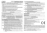
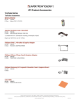
ACCESS CONTROL RECEIVER WITH DISPLAY AND PIN CODE PROTECTION Model RD448 for up to 448 key-fob transmitter users and event memory log. Model RD1000 for up to 1000 key-fob transmitter users. This receiver is designed to use in remote control and access control systems with large number of key-fob transmitter users and required high level of access control verification security. To achieve intended functional performance the receiver includes the following features & functions: - 448 key-fob transmitter user memory (model RD1-448) or 1000 key-fob transmitter users memory (model RD1-1000), - access to receiver programming procedures protection by user editable four digits PIN code password, - possibility of deleting a single key-fob user without need to clear entire user memory, - highly secure KEELOQ® dynamic code for remote key-fob user identification, - three digit bright LED display for user number display, easy programming, user key-fob learning and deleting, - very sensitive radio superhet receiver allowing better data signal selectivity and better operating range, - non-volatile memory log of last 6144 events (model RD1-448 only) including date, user number and key-fob button, - TAMPER switch with terminals allowing receiver’s case opening detection, - wide range of power supply voltages: 10…35VDC or 24VAC. Operation. The use of a key-fob transmitter learned to the receiver’s memory sets on its one of two relay outputs for: certain user programmed period of time (pulse – mono stable operation), or until a next use of key-fob transmitter is made ( on/off - bistable operation). The digital LED display will indicate number of used key-fob transmitter while receiver’s power on LED will change color (only if output one is set to on). Two pulses signal on relay set on and one pulse signal on relay set off would be generated at the receiver’s signal output S. Also, the event will be memorized in non-volatile event memory log for future reference. Mini-USB connector on the receiver’s board allows communication with PC. To connect the receiver to PC a popular Mini-USB cable with plug A type at one end (PC) and 5-pin mini-USB plug B type (Canon) at other end must be used. The cable is not included in the receiver set. Event Memory Log. The receiver is capable of memorizing last 6144 events. Every time a valid command from key-fob transmitter is received, it’s user number (0…447) is registered in the memory log along with information on used transmitter’s button (0..1) and current date/time. The content of the receiver’s event memory log may be read/printed out for reference or verification with the help of external personal computer (PC). Connection of the receiver and the PC is made by the use of Mini-USB cable. In addition, a dedicated software “RD Reader” supporting data log reading should be downloaded from manufacture’s web site www.elmes.pl and installed on the PC. The software allows reading out and saving of event chronological data log to PC in form of Microsoft Access® (*.mdb) data base file. Advanced editing and report listing of the *.mdb data file content may be done using Microsoft Access®, Lotus Approach® or Open Office® commercial software. RD receiver users are advised to read event memory data log the more frequently the higher the number of key-fob transmitters in the receiver’s memory. In a sample system with 448 key-fobs and their estimated twice use daily, receiver’s event log overflows after approximately 6 days. New event data is overwritten on existing data log in the memory. Internal Clock (RD448 only). Though the RD receiver’s memory is non-volatile type protecting data content in case of power cut off failure, the internal clock device is not protected and will stop time count on power off. Registered event data will therefore have incorrect timing after power supply is restored, proportionally to the power cut off timing. In order to maintain correct event timing, a battery backup power supply of the receiver must be used. Access Control. RD1000 receiver may be used to design access control system. To do so, the receiver must be mini-USB cable connected to PC. Every time keyfob transmitter is used its number along with used button number are sent to the PC via virtual COM port (*). If, within 100ms, PC does not confirm receipt by setting logic 0 at TX output of the COM port, the receiver’s relay output would remain off (**). This feature allows design own access control system in which one or more key-fob users may be temporarily or permanently restricted from entering secured premises. Elmes Electronic does not offer specific access control software for installation on PC. Access control mode is also available with the RD448 receiver model and requires solder shorting JP3 at bottom side of the receiver board. In this mode, the content of event memory log can not be read. (*) In ASCII format as: “NNN-P” followed by CR and LF commands, where NNN stands for key-fob number and P (0 or 1) for button used. (**) If receiver is not connected to USB port, a logic 0 is provided at at input RX securing receiver’s relay set on. odbiornik / receiver PC DATA PIN Code Protected Access To Programming Procedures. USB Access to receiver’s setup (Programming Procedures) is protected by four digits PIN code. It does not allow unauthorized persons to implement changes in receiver’s setup nor deleting or adding new key-fob users. Initial PIN code set by the manufacturer is “0000”. System owner tamper or administrator should change manufacturer’s PIN code to own (simple PIN codes, e.g. “1111” or “1234”, should be avoided). NOTE! To recover factory „0000” PIN code, if user’s code is lost or forgotten, the receiver must be send to distributor or manufacturer. Factory code refurbishing deletes receiver’s entire key-fob memory content. _ + S NC1 NO1 NC2 NO2 TAMP _ Description of jumpers. buzzer JP1 set on will result in key-fob number display for only 5 seconds. Set off will display last key-fob number until next key-fob is used. 12 - 24 V JP2 set on will result that only one output channel is active and responds to any user selected key-fob transmitter button. Set off both output channels are active and respond to two buttons of used key-fob, e.g. buttons 1 & 2 or 3 & 4 of Elmes CH4H transmitter. + e-mail: [email protected] internet: www.elmes.pl Elmes Elektronik 06.2011. All rights reserved. Installation. RD receiver operates indoor at ambient temperature range from 0 to +40°C. Installation place should be dry and far from any electromagnetic power lines, radio transmitters, metal screening and other devices that may cause interference and reduce operation range. External antenna should be used via coaxial cable connected to receiver’s ANT terminals if the receiver is to be installed inside any metal screened housing. Practical tests should be taken prior to firm installation to determine exact operation range. Standard wire antenna should be let loose downwards and not fixed or glued to ground. Receiver’s installation wiring is shown on schematic diagram. The second relay outputs (NC2 and NO2) are not operational with jumper JP2 set on. Connection of external buzzer shown on diagram is valid only when powering receiver with DC voltage. On AC voltage powering buzzer connection is prohibited! PROGRAMMING PROCEDURES Valid PIN code input is always necessary to access any below described programming procedures. If, within 16s from code acceptance, no procedure is started access is blocked again and flashing LLL sign displayed. 1. PIN code entry to access programming procedures: In order to access setup programming procedures it is necessary to enter protective PIN code, as in example: „6485” below: a) press shortly switch + , receiver display reads 1-0 , b) by consecutive depressing switch - select first digit of PIN code: c) press shortly + to accept and jump to next PIN code digit 2-0 1-6 , and by depressing - select second digit d) follow above steps to select 3rd and 4th PIN digits, as in the example e) flashing --- 3-8 and 4-5 , 2-4 , display confirms enabled access to setup procedures. NOTE: Incorrect PIN code entry is indicated by flashing E r r . Factory set PIN code is “0000”. 2. Learning key-fob transmitter to receiver’s memory cell and deleting selected memory cell content: a) press shortly switch + switch in the receiver – the display shows first clear memory cell to which a key-fob transmitter may be learned. b) by the use of + and - switches select required cell number (*). Lit dots at cell number indicate cell taken, as in example 0.2.5. while not lit dots indicate cell empty, as in example 0 2 5 , c) press shortly + and - switches simultaneously: if the cell is empty (dots off), learning a key-fob transmitter is started: if the cell is taken (dots lit) key-fob deleting within 15 seconds key-fob button must be double pressed – the LED display is started: - key-fob is deleted and the dots will start flashing and the procedure will end. To learn next key-fob transmitter turn to off with jump to subcl. “b”. follow subcl. “a” above. (*) Longer depressed switches allow faster memory reviewing. Exit from the procedure is made automatically if no switch is pressed within 30 seconds or, after pressing + and - switches simultaneously for longer than 2 seconds. NOTE! To learn key-fob transmitter already in memory of the receiver to any other cell must be preceded by deleting the transmitter from receiver memory. Otherwise, the transmitter is learned again to cell to which was already learned. 3. Selecting the receiver’s relay output time-lapse (pulse) or bistable (on/off) operation mode (possible with key-fob learned to RD receiver): a) press and hold depressed + switch until receiver’s display show PPP and then change to CCC . Release the switch. b) within 15 seconds press key-fob button (in two channel key-fob, the button of respective programmed channel). The receiver’s relay output sets to on and the display will show the key-fob number. For selecting time-lapse mode (pulse operation): For selecting bistable mode (on/off operation): c) After passing the required lapse time (from 0.25s up to 2 hours) press the c) Double press the key-fob button with less than 2 key-fob button again – output relay sets off. seconds interval - output relay sets off. d) After next two seconds displayed key-fob number starts flashing confirming properly performed procedure. 4. Deleting the content of event memory log (applicable to RD448 only): Press and hold depressed + and - switches simultaneously for more than 8 seconds, until receiver displays r r r sign. Releasing the switch starts deleting content of memory that may last up to one minute while still displaying r r r sign. 5. PIN code change: a) press and hold depressed + switch until display shows 1-0 (over 8s), and next release the switch, b) enter new PIN code following steps as in par. 1 (subcl. a..d) above, c) after entering 4th PIN digit display shows 1-0 again, d) repeat the enter of the new PIN code, e) flashing --- confirms end of the new PIN entry procedure . Errors are indicated by flashing E r r . Specification: - power supply: 10…35VDC or 24VAC; max. current: 130mA/10VDC, 100mA/12VDC and 50mA/24VAC; - standby current: 13mA/10VDC and 8mA/24VAC, output relay rating: 1A (120VA/30VDC); radio band: 433,92MHz; - memory of 448 or 1000 key-fob remotes; operating temp. range: -20 to + 40°Celsius; PIN code range 0000..9999; - signal output S (1A/60V) "open collector" type and generates pulses to receiver’s ground (minus of the supply voltage); Warning! Under no circumstances output S can be directly connected direct to + of the supply voltage! Serious damage may occur! Elmes Electronic declares that the product has been manufactured and tested to comply to the following standards: EN 60950-1 :2001 electric safety, EN 301 489-1 V1.4.1 (2002-08) EMC for radio equipment, EN 301 489-3 V1.2.1 (2002-08) EMC for Short Range Devices, EN 300 2203 V1.1.1 (2000-09) EMC and Radio Spectrum Matters. The product complies to RoHS directive. Manufacturer’s Limited Warranty: This product carries two year manufacturer’s warranty as from the date of purchase. The warranty is limited to the replacement of faulty original parts or repair defects of improper manufacture. Damage, faulty use or improper handling by the user or installer as well as any changes in product’s hardware or software caused by the user violets the warranty and all due repair costs will be charged. Elmes Electronic shall not bear liability for any personal or material damage resulting from any of its products direct, indirect or partial failure to operate properly. e-mail: [email protected] internet: www.elmes.pl Elmes Elektronik 06.2011. All rights reserved.