1
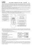
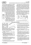
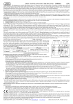
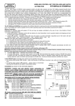
TWO RELAY OUTPUTS REMOTE CONTROL SETS WITH DYNAMIC CODE Models: U2HS, U2HSL, U2HR (receiver only) (EN) This manual covers the following remote control products operation, installation and programming: Equipment Type U2HS U2HSL U2HR Set Content receiver U2HR + 2 transmitters DWB100HT receiver U2HR + 1 transmitter DW200HT U2HR – receiver only Operating Range 100 m 200 m - Above specified products differ in number and type of used hand transmitters. All use the same receiver which features are described below. Easy allocation of hand transmitter buttons to control any receiver output Receiver is provided with two on-board programming switches: PRG1 for programming output one and PRG2 for programming output two. Both programming switches allow learning any hand transmitter button to control respective output. Moreover, the same button can control other output of the receiver, or two hand transmitter buttons can be learned to control one receiver output. These features allow the following control possibilities (examples): Some one button hand transmitters control operation of receiver output one, while other one button transmitters control output two. Any button of multi-button transmitter controls receiver output one, while any other button of the same transmitter controls output two. Two buttons of the same transmitter control one receiver output: one button sets the output on, while other sets the output off. One transmitter button controls two receiver outputs simultaneously, e.g. controlling two equipment units with galvanic separation. Remark: full flexibility of allocating any hand transmitter buttons to control any receiver outputs refers to use of Elmes transmitters with 1 to 4 control buttons and multi-channel hand transmitter STX. In the case of transmitters CH8H and CH32H certain limitations apply: buttons of two adjacent control channel banks cannot be learned to the same receiver, e.g. buttons from banks 1 & 2, or 3 & 4, etc. Receiver outputs operation modes Receiver outputs can operate in one of many modes selected by jumpers JP1 and JP2 and individually programmed to each output monostable (pulse), or bistable (on/off) timing modes (see pt 3 & 4 of programming procedures and table below). These allow range of solutions for various remote control applications, such as (examples): Pressed transmitter button sets receiver output on for programmed time. Next pressed, while in output set on state, prolongs set on time (mode A in Table below); Pressed transmitter button sets receiver output permanent on. Next pressed, sets output off (modes B, D & F); Pressed transmitter button sets receiver output on for programmed time. Next pressed, while in output set on state, sets output off (m.E); Pressed transmitter button sets receiver output permanent on (mode H), or for programmed time (mode G). Next pressed, while in output set on state, sets output off. This mode differs from two earlier described by that, it does not allow two outputs to be set on simultaneously. If output one is on and transmitter button learned to output two is pressed then output one sets off. Next pressed the same button sets output two on. This mode is used for electric motors control; As above, but remote control is performed with the use of single transmitter button only. Subsequent use of the same transmitter button sets on output one, sets the output off, sets on output two, sets the output off. This mode is also used for electric motor control (m. G & H); Pressed transmitter button sets output on. Subsequent use of the same button does not change output status. The output sets off when other button of the transmitter is pressed. This mode (B & D) is useful for secure switching on and off remote equipment not visible to operator. Pressed transmitter button sets receiver output on for as long as the button is pressed. Released button sets receiver output off. This remote control mode is frequently used by failed/damaged car transporter operators (mode C). Table of relay outputs available operation modes Jumper Status JP1 On JP2 On JP1 On JP2 Off JP1 Off JP2 On JP1 Off JP2 Off (1) (2) (3) (4) (5) Monostable Mode (1) A. Pressing transmitter button sets receiver’s relay output on for programmed time period. Next pressing of the button, while output is on, prolongs set on time of the output. C. Receiver relay output is set on for as long as transmitter button is pressed and sets off, after short delay, on button release (2,5) E. Subsequent pressing transmitter button set output on and off. If button is not used output sets off after programmed time. G. As above, except that two receiver outputs cannot be set on simultaneously – function useful for motor control (3) Bistable Mode (1) B. Each pressing of remote transmitter button sets receiver relay output on and off alternately (on/off mode), or one button sets on only while other sets off only (4) D. As above (4,5) F. Subsequent pressing transmitter button set output on and off. H. As above, except that two receiver outputs cannot be set on simultaneously – function useful for motor control (3) Output relay Monostable Mode (pulse) or Bistable Mode (on/off) is programmed in steps 3 and 4 of programming procedures. Delayed output set off reduces risk of unwanted interruptions in output set on continuity, due to interferences caused e.g. electric motors. Precise setting of this short delay timing is facilitated by programming 8-fold longer time delay of that needed. Example: to obtain 0.5s set off delay, programmed delay of 4..5s delay must be made initially (0.5 x 8=4). These modes also allow single transmitter button control of two receiver outputs. Subsequent use of transmitter button sets output one, sets the output off, sets output two on, sets the output off, etc. To obtain that transmitter button must be learned to only one receiver output. If transmitter button is learned to one receiver output, then subsequent pressing of this button alternately set on and set off that output. If two transmitter buttons (1 & 2 or 3 & 4) are learned to one receiver output, then odd buttons (1 & 3) always sets output on while even buttons sets the output off. Number of remote control transmitters that can be used in this mode is limited to 20. KEELOQ® Encoding System In the system, newly encoded control signal is generated and sent each time transmitter button is pressed. Receiver monitors code changes and responds to new code signals only. Once received code will not be accepted second time. This allows protection of radio transmission signals from deliberate code grabbing and unauthorized use. Receiver Relay Output Receiver is equipped with galvanic isolated relay output with NO (normally open) and NC (normally closed) three wiring terminals – one common. The output switches over on received set on signal. Details are shown on installation diagram included in this manual. LED Indication Receiver is equipped with two LEDs. Upper LED indicates power supply in red and switches to green on output 1 set on. Bottom LED is off on output 2 set off and shines green on output 2 set on. Signalling Output S Receiver features open collector type (OC) signalling output S for connecting to external acoustic siren or light strobe. The output generates two pulses shorting to receiver’s ground (-V) on any relay output set ON and one pulse on relay output set OFF in 0.5s pulse rate. Two pulses are e-mail: [email protected] internet: www.elmes.pl Elmes Elektronik 09.2013. All rights reserved generated also when pressed transmitter’s button is used to prolong timing of output set on in monostable mode only (mode A). In operation modes B and D, the use of transmitter button one generates two pulses and the use of button two generates one pulse. Transmitter Memory As each transmitter generates specific dynamic code, receiver must “learn” and memorize every transmitter it operates with. Therefore, capacity of its memory is limited to 104 transmitters, except in modes C & D when limit is 20 transmitters. Receiver Installation Receiver’s place of installation should be dry and away from electromagnetic power lines, radio transmitters, metal screening and other devices that may cause interference and reduce operation range. Receiver should be installed well above floor/ground level. It is recommended to test practical operating range of transmitter-receiver set prior to firm installation. Level of hand transmitter signals and unwanted radio interference signals can be checked using optional Elmes RFM indicator. PROGRAMMING PROCEDURES IMPORTANT! Wherever mentioned “PRGX” should be identified as PRG1 when programming receiver output , or PRG2 when programming receiver output 2. Main LED low flashing green confirms properly programmed procedure while fast flashing red indicates programming error. Programming procedure must be repeated. 1. Learning transmitter to receiver's memory with allocation of selected button to any receiver output. (If, by mistake, a button is allocated to control improper output, deleting single transmitter procedure applies, pt 2 below) a) Press receiver's PRGX switch for less than 2 seconds – main LED lights green. b) Press shortly selected hand transmitter button once - main LED changes to red. c) Press shortly the same hand transmitter button again. 2. Deleting single transmitter in receiver memory. This procedure applies also when changing allocation of transmitter buttons to receiver outputs. Important condition: transmitter to be deleted is available. a) Press and hold simultaneously switches PRG1 and PRG2 in receiver – main LED initially lights green and after 2s changes to red. Now, release both switches. b) Press shortly any button of the hand transmitter to be deleted. 3. Programming receiver output monostable operation mode (pulse) and output set on timing: a) Press and hold receiver's PRGX switch – LED lights green and after two seconds changes to red. Now release the switch. b) Press shortly the same PRGX. Relay in the receiver sets on and LED lights green. After required pulse time has lapsed press PRGX switch again. Within 2s receiver's LED starts flashing green confirming end of the procedure. 4. Programming receiver output bistable (on/off) operation mode: a) Press and hold receiver's PRGX switch – main LED lights green and after 2s changes to red. Now release the switch. b) Press shortly PRGX switch three times, with less than 2s intervals. Programmed receiver output sets on and off followed by main LED flashing green confirming end of the procedure. 5. Deleting all transmitters in receiver memory: Press and hold depressed simultaneously PRG1 and PRG2 for more than 8 seconds (till main LED flashes green). Now release the switch. All transmitters in receiver memory are deleted while programmed operation modes of outputs remain unchanged. Advice 1: Procedures 2, 3 and can be performed with the use of transmitter learned to the receiver memory. Advice 2: Time for performing procedures 1 and 2 above is limited to 30 seconds. If the procedures are not completed within this time period receiver exits programming mode and error is indicated. SPECIFICATION DWB100HT transmitter: radiated power < 5mW, battery: 12V (23A). DW200HT transmitter: radiated power < 10mW, battery: 9V (6F22). Receiver: - dynamic code system KEELOQ® of Microchip Corp. USA, - transmitter memory capacity: 104 (limited to 20 modes C & D), - superhet receiver module with sensitivity: -106 dBm, - power supply: 11…17 VDC, - current consumption: 20 mA + 20 mA for each relay set on, - operating temperature range from -20 to + 55°C, - monostable output timing: from 0,25s up to 4 hours, - bistable output mode: on/off, - signal output S (1A/60V max.) OC type, - sabotage alarm terminals NC type (closed box). - external dimensions (h/w/l): 24/46/73 mm Manufacturer ELMES ELEKTRONIK, 54-611 Wroclaw, Avicenny 2, PL tel. +48717845961, fax +48717845963 IMPORTANT! Output S must not be directly connected to (+) pole of power supply (see diagram above). Low battery in transmitters is indicated either by its LED flashing (DWB100HT) or dimming and failing to light (DW200HT). WARNING! Batteries may contain substances hazardous to human health. Do not place batteries in fire or household waste. Dispose of old batteries properly in accordance with local law regulations. Used batteries can always be disposed of at points of electronic waste collection. Manufacturer’s Limited Warranty This product carries two year manufacturer’s warranty as from the date of purchase. The warranty is limited to the replacement of faulty original parts or repair defects of improper manufacture. Damage, misuse or improper handling by the user or installer as well as any alterations in product’s hardware or software caused by unauthorized person violate warranty obligations and all due repair costs will be charged. Elmes Electronic shall not be liable for any personal or material damage or loss resulting from any of its products direct, indirect or partial use or failure to operate properly. e-mail: [email protected] internet: www.elmes.pl Elmes Elektronik 09.2013. All rights reserved