1
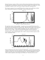
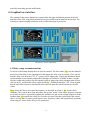
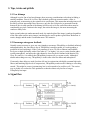
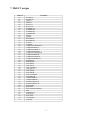
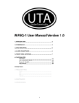
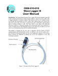
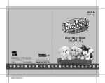
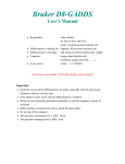
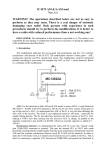
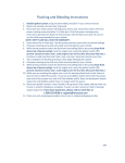
2WarpDelay User Manual
v1.0
dsp.mutagene.net
1. Introduction
Thank you for your interest in 2WarpDelay. 2WarpDelay has many of the features that you can find
in most other delays: independent delay lines for right and left stereo channels, cross-feedback for
control of the delay's stereo image, saturation, compressors in the feedback path to prevent harsh
clipping with extreme settings and filtering of the feedback paths. Unlike any other existing delay
effect, however, 2WarpDelay uses frequency-warped lattice filters (a rather esoteric type of digital
filter) in the feedback path with frequency responses that are determined per-channel by bitmaps.
For experienced and dedicated users, the novel use of warped filters offers near-total control over
the timbre of the delay. To inexperienced and experienced users alike, 2WarpDelay offers a new
and unique sound for their collection and the possibility for anything from subtly unusual delay
effects to wildly unpredictable yet surprisingly aesthetic feedback drones and atmospheres.
I hope that you will find 2WarpDelay useful in your compositions or sound design work. If so,
please visit dsp.mutagene.net to check for updates or browse for other VST effects or instruments.
2. Installation
2WarpDelay can be installed by copying the DLL to the VST plugins directory used by your host
application. No other files are necessary for it to run. If you are sharing effect patch .FXP or effect
bank .FXB files with others, though, and your patches use custom bitmaps, it is necessary to send
the bitmaps as well; saved .FXP/.FXB files will only contain the names and locations of the files.
3. Warped filters
This section gives a brief and somewhat technical overview of frequency warped filters. Although it
helps to understand some of the theory behind the filters, it isn't necessary in order to use the effect;
feel free to skip right through to section 4 (graphical user interface) if you just want to know what
all the controls do. Extensive experimentation with the effect should give you a good intuitive feel
for what the warp parameter does to filters.
A warped filter is a filter that has been modified so that its spectral resolution can be adjusted to
focus more on lower or higher frequencies (i.e., it provides a non-linear frequency resolution
between 0Hz and the Nyquist frequency). Because the human ear is most sensitive between 100Hz
and 2000Hz, it is more advantageous to focus the spectral definition on lower frequencies (and, in
fact, with 2WarpDelay it is not possible to warp the filter to focus more on the frequencies above
11kHz). Additionally, most notes used musically have fundamental frequencies in the range of 55Hz
(A1) to 880 Hz (A5), and since the timbre of a sound is most defined by the amplitudes of its first
few harmonics, it is logical that we should want a filter to also offer the ability to focus the greatest
resolution in this range.
-1-
Dynamic frequency-warping of a filter can also yield interesting and pleasing results by allowing
the adjustment of one parameter to change the entire frequency response of a complex filter, much
as adjusting "Frequency Cutoff" can sweep a resonant low pass filter to pleasing effect.
The frequency responses of two warped IIR lattice filters using the same coefficients are shown
below (note that the horizontal axis is logarithmic frequency measured in kHz).
Warp = 0
150
Magnitude (dB)
100
50
0
−50
−100
−150
−200
0.02
0.05 0.1 0.2
0.5
1
2
5
10
22
Illustration 1: A random unwarped lattice filter
The graph above shows an unwarped filter. As can be seen, the unwarped filter has most of its
spectral peaks in the region between 2kHz and 22kHz. What this means is that if you fed a plucked
guitar string sound (A2, 110Hz for example) through the filter, then it wouldn't be until its 10th
harmonic (at 10 x 110Hz = 1.1kHz) that any interesting frequencies would be boosted or
attenuated. Further, all the frequencies up until the 10th harmonic are heavily attenuated, so any
natural harmonic sound passing through the filter would lose almost all of the frequencies which
make it identifiably musical.
Warp = 0.9
150
Magnitude (dB)
100
50
0
−50
−100
−150
−200
0.02
0.05 0.1 0.2
0.5
1
2
5
10
22
Illustration 2: The random filter of Illustration 1 warped by a factor of 0.9
Using a warping factor of 0.9, however (pictured in Illustration 2), we can see how more spectral
resolution is concentrated on the lower frequencies where the human hearing apparatus has greater
resolution and where more relevant timbral information lies. Now the fundamental of a note at
110Hz would be emphasized, and starting around 500Hz (the 5th harmonic), there's a lot of
-2-
musically interesting spectral modification.
4. Graphical user interface
The controls for the stereo channels are separated into the upper and bottom portions of the lefthand side of the GUI, with global parameters being accessible from the panel on the far right. The
ordering of controls roughly reflects the order in which the signal is processed.
Illustration 3: GUI for 2WarpDelay
4.1 Delay, warp, resonance and cut
To the left of the bitmap display there are four bar controls. The first control, Dly, sets the channel's
delay time. If the delay is not synchronised to the tempo, the delay is set in seconds. If it is synced,
then the delay is set in terms of 16th, 8th, quarter, half or whole notes. Triplet and dotted note-based
synchronisation is not currently implemented, though it will likely be available in future versions.
In order to adjust the predelay for each channel (used for ping-pong echoes, amongst other effects),
click on on Dly, and the label will be replaced with Pre. Predelay defaultsl to "off". Keep in mind
that the total delay between a sound and its first echo will equal the sum of both the Pre and Dly
values.
Warp allows the filter to be warped in frequency, as described in section 3. Res sets the filter's
resonance. This controls how steep and narrow the spectral "peaks" in the filter's frequency response
are. Finally, because it is generally aesthetically desirable to avoid excessive high frequencies in the
feedback path, Cut controls the cutoff of a first order low pass filter that is placed after the warped
filter. Lowering the Cut control yields bassier, lower frequency echoes and is particularly important
when using low values for the Warp or Dly parameters.
-3-
4.2 Filter coefficient selection
In the middle of the left and right-channel panels there are bitmap displays. Above these there are
tab controls that set the method by which filter coefficients are selected. The three modes are Filter
Map, LP Analysis and Slave.
4.2.1 Filter Map mode
When the tab control is in Filter Map mode, filter coefficients are extracted from the bitmap (black
& white only) at the position indicated by the vertical orange line. The orange line that runs along
the bottom of the display indicates the length of the range that is scanned. It is not possible to set
the position being currently scanned using the GUI, but the parameter is available for automation
from the effect's host. Alternatively, the position can increment by one pixel every Step seconds, as
specified on the global parameters panel.
In order to set the left limit of the area being scanned from the bitmap, press the left mouse button
while holding down the Shift key. To set the right limit, press the right mouse button while holding
down Shift. The full extent of the image may be viewed by left-clicking and dragging the image.
Additionally, new bitmaps may be loaded by clicking the disk icon that extends from the upper right
hand corner of the filter map.
The icon below the disk icon and to the right of the main display controls the method in which the
coefficients are extracted from the bitmap. This feature will not currently be documented in detail
because its second and third (non-default) implementations are still in a state of flux. The default
mode will remain unchanged, however.
In short, the first mode extracts reflection coefficient values directly from the bitmap starting at the
bottom of the viewable area (indicated by the orange line). Bright pixels give positive values
(scaled by the Res parameter with white being close to 1) and black pixels give similar, negative,
values. Because reflection coefficients calculated from real signals have an average value that is
close to zero, the data is massaged slightly to remove a strong DC bias (non zero average). Entirely
black or white lines, for example, will be shifted to give identical reflection coefficients of all 0
(effectively making the filter nothing more than a delay).
In the second mode, the filter reflection coefficients are calculated by considering the entire height
of the image as representing its frequency response, much as it would in a spectrogram. The third
mode uses bandpass filters instead of a warped lattice filter and also tracks the image as if it were a
spectrogram. Unlike most filter banks, these bandpass filters change in frequency to "chase"
spectral peaks. The filter Step and smoothing Tc values may not function as expected in this mode.
Both the 2nd and 3rd modes use the entire height of the image, so that is why the orange line
(representing the location of the current coefficient extraction) extends the height of the image in the
window.
4.2.2 LP Analysis mode
If the control's LP Analysis mode is selected, then the channel's input (including feedback from itself
or the other channel) is continuously analysed using linear prediction analysis. The analysis occurs
at intervals specified by the Step control in the global parameters area. LP Analysis tries to choose
coefficients for the warped filter so that its frequency response matches the spectrum of the input
signal. If the channel were analysed and filtered using a single, same warping value, this would
-4-
theoretically mean that LP Analysis mode would merely boost those frequencies that are already
salient, leading to harsh whines and exponentially growing spectral peaks. The signal is analysed
using a fixed (for the time being) warping of 0.6, however, so if a different warping value is selected
by the user for the filtering, less predictable results can be achieved.
It should be noted that the LP Analysis mode can be very CPU intensive for short Step sizes, so the
user is advised to stick to longer intervals between analysis. The mode is also the least developed of
the three modes, and filter behaviour is a bit erratic.
4.2.3 Slave mode
Only the second (stereo right, bottom) channel supports Slave mode. In slave mode, the right
channel uses identical filter coefficients to the filter of the left channel. This does not mean that its
frequency response is necessarily the same, however - the user may use different warping, resonance
or low pass cutoff values to yield results that are subtly or wildly different from the left channel.
4.3 Saturation, compression, feedback
To the immediate right of the filter coefficient selection controls there are four bar controls that
allow saturation and compression of the feedback path to be affected. Sat sets the level of saturation.
Thr sets the threshold for the compressor, Ratio sets the ratio with which the signal is compressed
when it exceeds the threshold, and Att sets the rate at which the compression turns on and Rel
adjusts the rate at which it is turned off (with the vertical control setting the ratio between the two
values so that both may be adjusted using only the Att control).
In the left (top) channel, FbLL sets the feedback from the left channel to the left channel and FbLR
sets the feedback from the left channel to the right channel (likewise for the right channel). Note that
clicking in the vertical middle of the bar sets the feedback to zero, with positive feedback being
achieved by clicking above the middle and negative feedback by clicking below. It can fidgety to
find the "zero" mark using the mouse alone, so it is useful to remember that clicking the left mouse
button while holding down the Ctrl key will select the default (zero) value.
4.4 Global parameters
Looking briefly over to the global parameter section to the right of the GUI, Fade controls the rate
at which the effect fades out for zero input. This can limit ringing between percussive elements, or
can allow the effect to dissipate smoothly at the end of a song. At a value of 1.0, there is no fadeout
and for 0.0, the fadeout is instantaneous. Ord sets the order of the filter being used. The order of the
filter can be thought of as representing the number of "peaks" in the frequency domain (i.e., a filter
order of one would be like a bandpass filter, two would be like two bandpass filters, and so on), Step
controls the speed at which the bitmap is scanned (smaller numbers are faster), and Tc controls the
speed with which one filter morphs into the next.
Mix controls the mixing level (with 1.0 representing an entirely wet signal) and Out adjusts the
output gain of the effect. Below, oversampling can be turned on or off, the delay or speed with
which the filter coefficients are updated can be synchronized to song tempo, and the direction of
each delay can be set.
-5-
5. Tips, tricks and pitfalls
5.1 User bitmaps
Although it can be fun to load user bitmaps, there are many considerations to be taken in finding a
suitable candidate. First of all, in Filter Map's default coefficient extraction mode, a filter is
generally only as interesting as the variation in its coefficients. This means that smooth pictures will
not likely result in interesting filters. Moreover, only the first Ord pixels (as measured from the
bottom of the viewable portion of the bitmap) will be used, so for low order filters there must be
considerable per-pixel variation in the image; the noisier the image is, the more interesting the
results are likely to be.
In the second (otherwise undocumented) mode, the entire height of the image is analysed regardless
of the filter order and less noisy images can therefore be used to produce good filters. Behaviour is
erratic, though, and the mode is somewhat more CPU intensive.
5.2 Encourage outrageous feedback
It hardly seems necessary to go to any extra lengths to encourage 2WarpDelay to feedback infinitely
and unpredictably, but, since this is one of 2WarpDelay's strongest points, it's worth spending a
good deal of time exploring it. If the Fade parameter is set to 1.0 (for no fadeout) and feedback
levels are set high (preferably with a filter order of 17 or higher), it is easy to create desolate otherworldly atmospheres, and unless the right channel is slaved to the left channel with identical Dly,
Warp, Res and Cut, it is unlikely that 2WarpDelay's output will ever repeat exactly. Although it
almost makes things too easy, 2WarpDelay is in this sense ideal for drones and atmospheres.
If extremely short delays are used (less than 100 ms) in conjunction with highly resonant high order
filters (and matching high levels of compression), 2WarpDelay tends to make whining or screeching
sounds. This might be seen as just annoying, but it can be tamed to be useful as well. The easiest
way to do this is to reduce the Fade parameter so that the whines only last for so long as
2WarpDelay has input.
6. Signal flow
-6-
7. Midi CC assigns
Midi CC
20
21
22
23
24
25
26
27
28
29
30
31
32
33
34
35
36
37
38
39
40
41
42
43
44
45
47
48
49
50
52
53
54
55
56
57
58
59
60
61
62
63
64
67
68
69
70
Parameter
Predelay L
Predelay R
Delay L
Delay R
Reverse L
Reverse R
Feedback LL
Feedback LR
Feedback RL
Feedback RR
Warp L
Warp R
Resonance L
Resonance R
Cutoff L
Cutoff R
Compressor Threshold L
Compressor Ratio L
Compressor Attack L
Compressor Release L
Compressor Threshold R
Compressor Ratio R
Compressor Attack R
Compressor Release R
Saturation L
Saturation R
Loop Start L
Loop End L
Loop Y Offset L
Loop Index L
Loop Start R
Loop End R
Loop Y Offset R
Loop Index R
Analysis Mode L
Analysis Mode R
Extraction Source L
Extraction Source R
Filter Order
Step Time
Time Constant (smooth)
Mix
Output Level
Sync Delay
Sync Filter
Oversample
Fade Out
-7-
8. About the author
dsp.mutagene.net is home to plugins written by Alexis Glass. More VST plugins can be found at
http://dsp.mutagene.net. If you have any questions about this or other plugins, please contact me
(Alexis Glass) via [email protected]. If you find this or any other plugins on dsp.mutagene.net to
be indispensable and you feel compelled to express your appreciation monetarily, donations are
accepted via PayPal at [email protected]. Alternatively, I would be grateful if you took the time
to explore, and if interested purchase, my music (written as mutagene) on Databloem records
(http://www.databloem.com/).
Disclaimer
2WarpDelay is provided "as is" without warranty of any kind. The author makes no guarantee of
correctness, accuracy, reliability, safety or performance. You alone are responsible for determining
if this software is safe for use in your environment. Neither the author nor anyone else who has been
involved in the creation or delivery of this product shall be liable for any direct, indirect,
consequential, or incidental damages arising from the use or inability to use such product even if the
author has been advised of the possibility of such damages.
2WarpDelay is copyright © Alexis Glass 2004. The software is distributed as freeware and may be
redistributed under the condition that it is intact in its original zip archive format and its contents are
not modified in any way.
VST is a trademark of Steinberg Media Technologies GmbH.
-8-