1
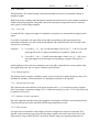
KISTLER
Piezo-Messtechnik
Betriebs-und
Serviceanleitung
Notice d’emploi et
De maintenance
Operating- and
Service-instructions
TYPE
9261A
MULTI-COMPONENT MEASURING PLATFORM
FOR BIOMECHANICS AND INDUSTRY
Sn ……….
9261A
B6.9261e 12.74
2
OPERATING INSTRUCTIONS
MULTI-COMPONENT MEASURING PLATFORM FOR BIOMECHANICS AND INDUSTRY
Table of Contents
Section
Page
Table of Contents ...................................................................................................................................... 2
1
DESCRIPTION ................................................................................................................................. 4
1.1
Introduction ............................................................................................................................... 4
1.2.
Technical data............................................................................................................................ 5
1.3.
Explanations to the Technical data............................................................................................ 6
1.3.1.
Ranges ............................................................................................................................... 6
1.3.2.
Overload ............................................................................................................................ 6
1.3.3
Calibrated ranges............................................................................................................... 7
1.3.4
Sensitivity.......................................................................................................................... 7
1.3.5
Sensitivity variations ......................................................................................................... 7
1.3.6
Linearity ............................................................................................................................ 7
1.3.7
Hysteresis .......................................................................................................................... 8
1.3.8.
Threshold........................................................................................................................... 9
1.3.9.
Cross talk.......................................................................................................................... 9
1.3.10. Natural frequency .............................................................................................................. 9
1.3.11
Thermal sensitivity shift.................................................................................................... 9
1.3.12. Influence of cable capacitance........................................................................................... 9
1.3.13. Time constant .................................................................................................................... 9
1.4.
Construction of the measuring platform.................................................................................. 10
1.5.
Examples of applications......................................................................................................... 10
2. INSTALLATION............................................................................................................................ 10
2.1
General information ................................................................................................................ 10
2.2
Mounting base ......................................................................................................................... 11
2.3.
Mounting the measuring platform........................................................................................... 12
2.4.
Special mountings ................................................................................................................... 14
3. OPERATION .................................................................................................................................. 14
3.1.
Basic circuitry of the measuring system.................................................................................. 14
3.2
Switching possibilities on the platform ................................................................................... 15
3.3
Switching the system for 1, 2 or 3 force components ............................................................. 15
3.4.
Switching the system for measuring additional components .................................................. 16
3.5.
Range selection and resolution................................................................................................ 16
4. SIGNIFICANCE AND PROCESSING OF THE OUTPUT SIGNAL........................................... 18
4.1.
Nomenclature .......................................................................................................................... 18
4.2.
Reference coordinate system................................................................................................... 19
4.3.
Correlations between forces and moments acting on the measuring platform and output
signals 19
4.4.
Processing the output signals .................................................................................................. 23
5.1
Calibration ............................................................................................................................... 26
5.1.1.
Works calibration ............................................................................................................ 26
5.1.2.
Subsequent calibration .................................................................................................... 26
5.2.
Maintenance parts list.............................................................................................................. 26
9261A
ILLUSTRATIONS AND TABLES
B6.9261e 12.74
3
Page
Figures
Figure 1. Multi-component measuring platform for biomechanics and industry, Type 9261A................ 4
Figure 2. Dimensions of the measuring platform (measuring surface hatched: 440 x 264 mm2) ............ 5
Figure 3. Linearity..................................................................................................................................... 8
Figure 4. Cross section through the measuring platform. ....................................................................... 10
Figure 5. Installing the measuring platform. ........................................................................................... 12
Figure 6. Mounting plate ......................................................................................................................... 13
Figure 7. Connections and switches of the platform ............................................................................... 15
Figure 8. Measuring small dynamic changes in a large fundamental force. ........................................... 17
Figure 9. Definition of the measurands. .................................................................................................. 19
Figure 10. Layout of typical measuring systems..................................................................................... 25
Tables
Table 1. Technical data.............................................................................................................................. 5
9261A
1
DESCRIPTION
1.1
Introduction
B6.9261e 12.74
The multi-component measuring platform Type 9261A is a piezoelectric transducer with which the
following measurands can be determined:
•
the 3 components Fx, Fy and Fz, of the applied force F
•
the 2 coordinates ax and ay of the point of force application
•
the free moment M'z about an axis normal to the platform surface.
The four 3-component quartz transducers fitted give the platform a high rigidity, thus minimal
measuring deflections and wide frequency range.
The electrical charges yielded by the platform are strictly proportional to the measurands. They are
converted by charge amplifiers into analog dc voltages, after which they can be recorded, displayed or
otherwise processed as required.
The measuring platform Type 9261A is employed primarily for investigations in biomechanics (sport,
orthopedics, neurology, ergonomics etc.) and in industry (automotive engineering etc.).
Figure 1. Multi-component measuring platform for biomechanics and industry, Type 9261A
4
9261A
1.2.
B6.9261e 12.74
5
Technical data
Figure 2. Dimensions of the measuring platform (measuring surface hatched: 440 x 264 mm2)
Table 1. Technical data
Ranges:
(Each axis loaded separately, force application
point inside measuring surface, work plane not
more than 100 mm above platform surface
i.e. |az| ≤ 137 mm
Overload
Overload for each range, loaded singly. The
measuring platform installed according to
instructions (see Section 2) cannot be damaged
by a human being in ordinary civilian or sports
clothing, without tools.
Calibrated ranges:
Fx, Fy: each
Fz
Ax
Ay
M’z (Fx = Fy =0)
Fx, Fy : each
Fz
kN
kN
mm
mm
kNm
±5
0…10
± 200
± 300
± 2.5
%
120
KN
KN
0…5
0…10
9261A
Sensitivities (nominal values):
B6.9261e 12.74
Fx, Fy : each
Fz
Sensitivity variations:
Force application point within measuring surface
indicated
Force application point within the whole top plate
Linearity: all ranges
Hysteresis: all ranges
Threshold: Fx, Fy, Fz
Cross talk:
F,' Ö Fy
Fx , y Õ F,
Fz Õ F x , y
Operating temperature range:
Thermal sensitivity shift:
Natural frequency without additional coverings, lowest observed:
Insulation resistance, each channel:
Capacitance per connection, switches open or closed:
Specifications for installation surface on which measuring platform
is mounted, see Sub-section 2.2.
Platform material:
Weight:
1.3.
6
PC/N
PC/N
-7.5
-3.3
%
≤±2
%
≤± 5
% FSO
%FSO
MN
%
%
%
°C
°C-1
Hz
TΩ
pF
≤± 1
≤ 0.5
< 50
≤±2
≤±3
≤±l
0 ... 50
≈ -2 • 10-4
>200
>10
<400
Cast aluminum
kg
26
Explanations to the Technical data
The terms and their definitions are based largely on ISA standards (Instrument Society of America).
The notation (ISA) refers to the standard ISA-S 37.1/1969. Definitions with the notation (KIAG) have
been created by us specially for our instruments.
1.3.1. Ranges
Range (ISA): The measurand values over which a transducer is intended to measure, specified by their
upper and lower limits.
All specifications are maintained within the range.
Because this instrument measures simultaneously in 3 axes, the ranges indicated for the individual
components can be fully exploited only if one component at a time acts as load. With combined
loadings the admissible ranges are reduced (see also 1.3.2.).
In critical cases the makers or their representatives should be consulted.
1.3.2. Overload
Overload (ISA):The maximum magnitude of measurand that can be applied to a transducer without
causing a change in performance beyond specified tolerance.
9261A
B6.9261e 12.74
7
For use in biomechanics the overload is not only given as range percentages, because in practice it is
not possible for example to ask an athlete to load the platform only within certain limits. The platform
has been designed so that it cannot sustain damage if used for its intended purpose, provided it is
installed properly. Thanks to the special properties of piezoelectric transducers, measured values falling
unintentionally outside the range, but still inside the overload, are usable in most cases.
1.3.3
Calibrated ranges
These ranges are calibrated individually at the works. The results are recorded on calibration sheets
which are issued with the instruments. The high linearity of quartz transducers allows the same values
to be used for partial measuring ranges (see also 1.3.4.).
1.3.4
Sensitivity
Sensitivity (ISA): The ratio of the change in transducer output to a change in the value of the
measurand.
Here the slope of the “best straight line” through the zero is given as the sensitivity (see 1.3.6.).
The sensitivities quoted here are nominal figures. Each instrument is accompanied by individual
calibration sheets giving the exact values (see also 1.3.3. and 1.3.5.). Because the sensitivity of each
instrument is constant over wide ranges, the same sensitivities are valid also for partial measuring
ranges.
1.3.5
Sensitivity variations
When the measuring platform is installed according to the instructions, the sensitivity will vary no
more than specified, provided the force application point remains within the limits stated.
1.3.6
Linearity
Linearity (ISA): The closeness of a calibration curve to a specified straight line.
For piezoelectric force transducers this straight line is determined as follows (see Fig. 3: to make things
clearer the curve has been distorted in the direction of the ordinate
9261A
B6.9261e 12.74
Figure 3. Linearity
Two parallels are sought lying as close together as possible and enclosing the entire calibration curve.
In addition a third parallel midway between the first two must pass through the zero (no force, no
output signal). The slope of this mid-parallel is the sensitivity of the transducer. Half the distance
between the two parallels, measured in the direction of the ordinate and expressed as a percentage of
the full scale output, is the linearity.
This definition describes the independent linearity with forced zero.
Although the quartz itself yields an electrical charge exactly proportional to the load, certain
unavoidable deviations result from the mechanical assembly. In each partial range, including the uncalibrated ones, the linearity remains within the percentage stated for the end value of the partial range
in question. FSO means full scale output i.e. the algebraic difference between the outputs
corresponding to the measurands at the upper and lower range limits.
1.3.7
Hysteresis
Hysteresis (ISA): The maximum difference in output, at any measurand value within the specified
range, when the value is approached first with increasing and then with decreasing measurand.
Quartz itself has a virtually non-measurable hysteresis. Owing to the mechanical assembly a measurable hysteresis may occur, but in every range it lies below the stated percentage of the particular FSO.
If more hysteresis is detected this means that the platform has not been mounted property.
8
9261A
B6.9261e 12.74
9
1.3.8. Threshold
Threshold (ISA): The smallest change in the measurand that will result in a measurable change in
transducer output.
With piezoelectric transducers the threshold is limited by the inherent noise of the transducer and above
all that of the charge amplifier. The stated value of the measurand corresponds to about 3 times the
noise signal of a usual charge amplifier.
1.3.9. Cross talk
Crosstalk (KIAG): Signal at an output of a transducer in response to a measurand not assigned to that
output.
Cross talk is expressed as the ratio of the measurand corresponding to that output signal to the
measurand causing the cross talk. If both measurands have the same dimension, the cross talk can be
expressed as a percentage.
Examples:
a) Cross talk Fx Õ Fz = 0,8 % means that under a load of, say, Fx = 100 N a cross talk
signal appears at the Fz output corresponding to a genuine Fz signal of 0,8 N.
b) Cross talk F, Õ Mz = -3 Nm/kN means that under a load of, say, Fz = 1 kN a cross
talk signal appears at the Mz output corresponding to a genuine Mz signal of - 3
Nm.
On this platform with its four force transducers, the cross talk is dependent also on the position of the
force application point, but it is always within the specified limits.
1.3.10. Natural frequency
The platform forms a complex oscillatory system. In practice the lowest natural frequency observed is
dominant all, channels, for this platform it is a diaphragm oscillation of the top plate.
1.3.11 Thermal sensitivity shift
This value describes the behaviour of the quartz element itself, i.e. it is a material property of quartz.
Since for example a temperature change of 50 °C shifts the sensitivity by only 1 % or so, this effect can
be ignored in most cases.
1.3.12. Influence of cable capacitance
The cable capacitance and hence the cable length have practically no influence on the measured result
if the prescribed special cables and KIAG SWISS charge amplifiers are used.
1.3.13. Time constant
For quasi-static measurements a knowledge of the time constant to be expected is important. This
depends on the measuring range selected on the charge amplifier and varies from about 100 s in the
most sensitive range to about 100 000 s in the least sensitive range (see operating instructions for
9261A
B6.9261e 12.74
10
charge amplifier Type 5001).
1.4.
Construction of the measuring platform
Figure 4. Cross section through the measuring platform.
The measuring platform is shown in cross section in Fig. 4. Four 3-component force transducers (1)
Type 9251 are pre-stressed between the base plate (2) and the top plate (3) with the pre-stressing bolts
(4). The space between the two plates is sealed with a special rubber strip (5).
At one end there are eight TNC connectors (6). With switches (7) that can be operated from outside, all
switching combinations can be selected for measuring up to three force and three moment components
(Figs. 8, 9 and 1 0).
The platform has four supporting surfaces (8) concentric with the four transducers (see Section 2).
1.5.
Examples of applications
Examples applications for the multi-component measuring platform in biomechanics and industry are:
•
•
•
•
•
•
•
Investigations in biomechanics, e.g. measuring the forces exerted by the human foot in walking,
standing etc.
Orthopedic investigations
Monitoring of rehabilitation progress, e.g. with prostheses, after fractures etc.
Investigations for sport, e.g. optimizing sequences of movements to achieve top performance
Neurological investigations, e.g. Romberg test, psychomotor activities etc.
Measuring reaction forces between car tires and ground
Dynamic and static determination of coefficients of friction, e.g. between shoes and different
floor coverings.
2.
INSTALLATION
2.1
General information
The platform is a measuring instrument whose inherent accuracy can be exploited and retained only if
9261A
B6.9261e 12.74
11
it is properly installed and treated.
In particular it is absolutely essential that the mounting instructions are observed strictly and exactly if
damage due to overloading (e.g. excessive internal stresses etc.) is to be avoided.
The makers disclaim all responsibility for damage when the mounting instructions are not followed
properly.
2.2
Mounting base
The special advantage of piezoelectric force measurement - smallest measuring deflections even
under the largest forces, i.e. high rigidity - means also that the platform is very sensitive to inadequately
accurate support. Consequently it must be mounted only on a very rigid base, such as a mounting base
(see also 2.4.).
The measuring platform stands on the base with four circular supporting surfaces which are concentric
with the four transducers.
To ensure a perfect support a special frame of hot-galvanized steel is supplied with the platform. If this
frame is grouted into a concrete pedestal according to instructions, all requirements for the measuring
platform support are met and it can be mounted without difficulty.
Procedure for concreting-in the mounting frame:
•
•
•
•
•
•
•
•
Inspect the frame for any damage in transit before grouting it in. Make sure that it is square and
that the flat steel forming the frame has not been bent.
Insert the four stone bolts (see Fig. 5) and secure with the lock nuts.
Beside each stone bolt is a mounting bolt (4) for the measuring platform. This must remain
screwed in during grouting. The threads must be greased beforehand, so that the bolts can be
loosened again afterwards.
Place the frame in the prepared concrete foundation.
Level the frame exactly with a precision spirit level. The supporting surfaces must lie in the
same horizontal plane to within ± 0,l mm. Check also the diagonals of the four supporting
points (6) (440 x 264 mm2 ).
Grout the foundation without moving the frame from its exact position. It is advisable to leave
the upper cross members projecting a little above the surrounding concrete surface.
Make sure that the grout goes tightly under the upper cross members.
Check once again that the supporting points are in the horizontal position as prescribed.
Important: If the platform is installed outdoors, the concrete foundation must be bedded in gravel at a
frost-proof depth.
Leave sufficient space for the mounting angles at both sides of the platform (see Fig. 5).
A duct for up to eight connecting cables must be provided at the appropriate end of the platform, in the
direction of the positive y-axis. The cables are in flexible metal tubing of 10 mm outside diameter and
should not be bent with a radius of less than 50 mm. If the facility of direct switch cover at the platform
is to be exploited, a removable cover should be provided, so that the switches can be operated with a
screwdriver.
Between the platform and the surrounding floor a gap of at least 2 mm must be left. Floor coverings
9261A
B6.9261e 12.74
such as Tartan must likewise be interrupted at the edge of the measuring platform to prevent any
parasitary force shunts.
Figure 5. Installing the measuring platform.
1.
2.
3.
4.
5.
6.
7.
8.
9.
10.
Measuring platform 9261A
Mounting frame
Mounting angle
Mounting bolts with washers
Stone bolt with hexagon nut
Supporting surfaces of platform, 40 mm diameter.
Shim to take up any play
Concrete foundation
Cable duct
Minimum height 60 mm, total height according to selected covering (e.g. Tartan)
2.3.
Mounting the measuring platform
Clean all supporting surfaces properly
•
•
Place the platform in position
Press lightly with the fingers to check whether the platform has diagonal wobble.
12
9261A
B6.9261e 12.74
13
If there is discernible play, this must be rectified by shimming (a set of shims is supplied). Only one
corner should need shimming normally. If the thickness grading of the sheets supplied is not sufficient,
the residual play can be taken up with household type aluminum foil.
Fine adjustment is achieved as follows
•
•
•
•
•
•
Open switch between connections Y1+4 and Y2+3 (screw slot vertical, see Fig. 8)
At Y1+4 connect a charge amplifier and an indicating instrument(e.g. voltmeter, preferably with
a range – 10V … +10 V).
Adjust the charge amplifier to a sensitivity of 7,5 pC/N and a range 20 N/V (2 x 10 mechanical
units/volt). Time constant to long.
Load platform centrally, either by standing on it steadily or placing a mass weighing about 50
kg on it, and note the voltmeter reading.
Minimum reading under load indicates good positioning of the platform. If more than ± 5 V is
shown, by pressing lightly with the fingers, find the corner that still needs shimming.
The reading should remain ± 5 V when the force application point is moved within the
measuring surface.
After making the fine adjustments the platform can be secured with the mounting angles (see Fig. 6)
Figure 6. Mounting plate
It is advisable to use the washers under the M10 mounting bolts, as this minimizes the danger of the
mounting angles getting damaged or turned out of position.
9261A
B6.9261e 12.74
14
Important: The mounting angles are not intended to clamp the platform down the floor, only to prevent
it from shifting. Before screwing on therefore, check whether the angles can be pressed onto the
supporting surface with the fingers. With correct fitting this should be possible, and the foam rubber
will be pressed only lightly.
While the M10 mounting bolts are being tightened up, press on the fixing angle constantly with the
fixing angles to make sure that this does not cant.
The voltmeter must not respond to the tightening of the fixing angles! If it does, the angle in question is
jammed.
It is advisable to provide a covering frame around the platform, covering both the cable duct and the
mounting angles.
Important: The platform must be protected against direct sunlight, otherwise thermal expansion may
overload the very rigid force transducers due to internal stresses.
2.4.
Special mountings
In certain applications maximum forces occur that are well below the maximum ranges. This is
particularly true with investigations outside the field of sport, such as in orthopedics, rehabilitation,
neurology etc.
In such cases the platform may also be laid on relatively softer floors, such as linoleum.
•
•
•
•
•
•
The following instructions must then be observed, however:
The floor must be the same under all four supporting surfaces (same material, same elasticity).
The floor must be plane to within 1 mm.
The platform must rest only at the four supporting points.
It must be installed exactly as described in sub-section 2.3., though in this case the fixing angles
can be omitted.
The forces applied must not exceed 25 % of the ranges. If any question or doubts arise with
such applications, the makers or their representatives must be consulted.
3.
OPERATION
3.1.
Basic circuitry of the measuring system
The electrical charges (in pC) yielded by the measuring platform are converted by charge amplifiers
into proportional voltages, which can then be indicated, recorded or otherwise processed with the usual
equipment. The connecting cables from the platform to charge amplifier must have extremely high
insulation (>100TΩ)and low frictional electricity. Consequently special cables must be used
exclusively (see data sheet 15.01 1).
Ordinary cables may be used from the charge amplifiers to the indicating instruments.
The electrical connectors should always be handled with great care and cleanliness. The protective caps
of the plugs should only be removed immediately before connecting.
9261A
B6.9261e 12.74
15
Note: The plug protection caps of the platform are best screwed to those attached to the connecting
cables (e.g. Type 1619) by chains. In this way they cannot get lost or dirty inside.
If contacts or insulation get dirty, they can be cleaned with Freon TF (Type 1001) or white gasoline.
The insulation resistance can be measured with a teraohmmeter (e.g. KIAG SWISS Type 5491).
3.2
Switching possibilities on the platform
The measuring platform has eight outputs (see Fig. 7). Between the outputs relating to the same coordinate axis are switches, enabling the adjacent outputs to be paralleled or separated.
Highly insulating reed relays are employed as switches, operated by a permanent magnet rotatable from
outside.
Switch positions:
Screw slot horizontal:
Screw slot vertical:
Switch closed
Switch open
Important: The switches between outputs connected to a charge amplifier each must not be closed,
otherwise the amplifier will go into saturation at once!
If outputs are needed from only one or two axes, the outputs belonging to the coordinate axis not in use
must be paralleled and short-circuited with a short-circuit cover Type 1875. If this is not done, the
measurement may be falsified by electrical cross talk!
Figure 7. Connections and switches of the platform
3.3
Switching the system for 1, 2 or 3 force components
This is the simplest operating mode.
All switches on the platform must be closed, i.e. screw slots horizontal (see Fig. 7).
A charge amplifier and a connecting cable are needed for each of the three channels Fx, Fy, and Fz. It is
immaterial whether the cable of the Fx channel is connected X1+2 or X3+4 for instance; the same applies
to Fy and Fz.
9261A
B6.9261e 12.74
16
Each of the three amplifiers is to be adjusted to the respective sensitivity given on the calibration sheet.
3.4.
Switching the system for measuring additional components
By opening switches on the platform and switching in further amplifiers, up to six components can be
measured. The complete correlations and possibilities are dealt with in detail in Section 4.
3.5.
Range selection and resolution
It is best to use charge amplifiers with calibration factor adjustment for the measuring platform, such as
the KIAG SWISS charge amplifier Type 5001. The sensitivities are adjusted according to the values for
the Fx, Fy and, Fz channels quoted in the calibration sheets. In this way the output voltage is adjusted
directly to the values corresponding to the selected measuring range (... N/V).
An excellent feature of piezoelectric measurement is that small force changes can be measured very
accurately in the presence of a high preload.
For this it is enough (see Fig. 8), after applying the preload (e.g. a person steps onto the platform), to
switch the amplifier to reset, select a range of appropriate sensitivity, and then switch the amplifier
back to operate. Even the smallest forces can then be registered dynamically (e.g. by cathode-ray
oscilloscope), such as movements of a finger or in extreme cases the force changes resulting from the
pulse, i.e. the ballistocardiogram.
9261A
B6.9261e 12.74
17
Figure 8. Measuring small dynamic changes in a large fundamental force.
A:
B:
C:
D:
E:
F:
G:
H:
I:
J:
K:
L:
Amplifier to Reset, range selected for Fz: 100 N/V (amplifier to Long Time Constant).
Amplifier to Operate.
Fz is applied (person steps onto platform).
After reading or recording the weight, switch amplifier to Reset once more- The charge
corresponding to Fz is thus eliminated
Switch over to more sensitive range for ∆ Fz (e.g. 1 N/V).
Select Short Time Constant,
Set amplifier to Operate.
The variations ∆ Fz can now be measured with great accuracy, because the dynamic
threshold is about 0,02 N, i.e. a ∆ Fz of 0,02 N (as a change in Fz ≈ 800 N) now gives an
output voltage of about 20 mV.
Amplifier to Reset.
Switch back to less sensitive range (100 N/V), Long Time Constant.
Amplifier to Operate.
The disappearance of Fz (person steps off the platform) can also be registered.
9261A
B6.9261e 12.74
4.
SIGNIFICANCE AND PROCESSING OF THE OUTPUT SIGNAL
4.1.
Nomenclature
a
Distance between transducer axes and y-axis (for 9261A: a=132 mm)
ax
ay
az
Coordinates of the intersection point of the line of action of the resultant
with the (x, y)-plane translated parallel by az (working plane)
Distance between working plane and (x, y)-plane
b
Distance between transducer axes and y-axis (for 9261A: b = 220 mm)
F
Resultant of all forces acting on the platform
Fx
Fy
Fz
Components of the resultant
Fxl … FX4
Fy1 … FY4
Fz1 … FZ4
Force components in x-direction acting on transducers 1 ... 4
Force components in y-direction acting on transducers 1 ... 4
Force components in z-direction acting on transducers 1 ... 4
M
Resultant moment vector after reducing all acting forces and moments to the
origin of coordinates
18
Mx
My
Mz
Components of the resultant moment vector
M’
Free moment vector resulting from all acting free moments
M’x
M’y
M’z
Components of the resultant free moment vector
0
Origin of coordinates
σz
Normal mechanical stresses in the test object/measuring platform interface (a >
0 corresponds to compression
x
y
z
Reference coordinate system
9261A
B6.9261e 12.74
19
Figure 9. Definition of the measurands.
4.2.
Reference coordinate system
A positive Cartesian coordinate system is used as reference coordinate system. The z-axis is normal to
the platform surface, and the positive direction points into the platform. The positive y-axis points
towards the end with the connections.
A positive Cartesian coordinate system is defined as follows:
Looking in the direction of the positive x-axis, a rotation of the positive y-axis through 90° into the
positive z-axis appears clockwise. Similarly the positive moment vector M constitutes a clockwise
rotation looking in the direction of the positive x-axis.
The same is true of the y- and z-axes by cyclic rotation.
4.3.
Correlations between forces and moments acting on the measuring platform and output
signals
Note: The following individual transducer outputs are paralleled permanently and are designated and
defined as measuring platform outputs as follows:
Output:
9261A
B6.9261e 12.74
20
X1+2 : Fx1+2 = Fx1 + Fx2
X 3+ 4 : Fx3 +4 = Fx + Fx4
3
Y1+ 4 : Fy1+4 = Fy1 + Fy 4
Y2+3 : Fy2 +3 = Fy2 + Fy3
Components of the resultant:
Fx = Fx1+2 + Fx3+4
(1)
(2)
(3)
Fy = Fy1+4 + Fy 2+3
Fz = Fz1 + Fz2 + Fz3 + Fz4
Resultant:
(
F= F +F +F
determined by the angle γ’ to the (x, y)-plane
2
x
2
y
2
z
)
(4)
1
2
Fz
sin =
'
(5)
F
and the angle δ of the projection of F onto the (x, y)-plane to the positive x-axis:
F
tan = y
Fx
(6)
or determined by the direction cosines
angle α between the resultant and the positive x-axis
Fx
F
cos =
(7)
angle β between the resultant and the positive y-axis
F
cos = y
F
(8)
angle γ between the resultant and the positive z-axis
cos =
Fz
(9)
F
(Note: cos2α + cos2β + cos2γ = 1
Components of the resultant moment vector (referred to origin of coordinate)
(
My = a(− F
M = b(− F
M x = b Fz1 + Fz2 − Fz3 − Fz4
z1
z
)
+ Fz2 + Fz3 − Fz4
x1+2
) (
)
+ Fx3+4 + a Fy1+4 + Fy 2+3
(10)
(11)
(12)
)
9261A
B6.9261e 12.74
21
Generally a multi-component force and moment measuring system yields not more than the 3
components of the resultant, its direction in space (though not its position!) and the 3 components of
the resultant moment vector referred to the origin of coordinates.
In other words:
Only the resultant translated through the coordinate origin and the resulting moment vector referred to
the origin of coordinates are obtained.
Let us take the equations for determining the resultant moment vector M (see Fig. 9):
M x = ay • Fz − a z • Fy + M x′
M y = −a x • Fz + az • Fx + M y′
M z = ax • Fy − a y •Fx + M z′
(13)
(14)
(15)
and assume for the time being that no free moments are acting on the measuring system, i.e.:
M’x = M’y = M’z =0
Since Fx, Fy, Fz, Mx, My, and Mz are measured by the system, for determining ax, ay and az,
equations (13), (14) and (15) can be rewritten as follows:
0• ax + Fz • a y − Fy • az = M x
(16)
−Fz • ax + 0• ay + Fx •az = M y
Fy • ax − Fx • ay + 0• az = M z
The determinant of this system equals 0, because all coefficients of the main diagonal are equal to 0,
i.e. the system is indeterminate for ax, ay and az.
Because it is a linear equation system, however, it determines a straight line (i.e. the action line of the
resultant ) with a),, a ax, ay and az as the coordinates of a point running on it. The point of force
application is thus simple to find: it is enough to determine the intersection of the action line with a
given plane.
Example: For the working plane of the measuring platform Type 9261A the equation is:
az =-37mm
(17)
This value has only to be substituted in equation (16) to obtain the coordinates ax and ay of the force
application point in the working plane.
In the general case, however, there are free moments acting on a multi-component measuring system as
well. System (16) then appears as follows:
0 • ax + Fz • ay − Fy • az = M x − Mx′ = ?
−Fz • ax + 0• ay + Fx • az = M y − My′ = ?
Fy • ax − Fx • ay + 0 • az = Mz − Mz′ = ?
(18)
9261A
B6.9261e 12.74
22
The measuring system can measure only Fx, Fy, Fz, Mx, My and Mz, (see equations (1), (2), (3), (10),
(11) and (12).
Though the components and M'x, M’y, and M’z, of the free moment vector are contained in the
components Mx, My and Mz of the resultant moment vector, their magnitude is not known.
In other words:
Since M’x, M’y, and M’z are not known, the constants of system (18) also remain unknown. The
equation system (18) not only determines the action line of the resultant therefore, but also comprises
all straight lines parallel to the action line.
Or to put it in another way yet:
In the general case it is impossible to say of a measured moment whether it is generated
only by a force eccentric to the origin of coordinates, or only by a free moment, or by any
combination of the two.
Special case of measuring platform Type 9261A:
No free moments M'x and M'y can act on the platform, thus:
M’x = M’y = 0
Why?
In the intended applications of the measuring platform (standing, walking, running, driving, rolling,
jumping on and off it) no tensile stresses are imposed on its surface, i.e. the interface test
object/measuring platform:
σz ≥ 0
(19)
Fz = σz, dA ≥ 0
(20)
from which it also follows that
On the other hand a free moment M'x or M’y would impose tensile stresses too (σz < 0), because a free
moment can always be represented by a force couple (two parallel forces, equal but of opposed signs).
But as long as the condition σz ≥ 0 is fulfilled, no force couple forming M’x or M’y, can arise.
For the measuring platform Type 9261A the equation system (18) can therefore be written as follows:
0 • ax + Fz • ay − Fy • az = M x
−Fz • ax + 0• ay + Fx • az = M z
Fy • ax − Fx • ay + 0 • az = Mz − Mz′
9261A
B6.9261e 12.74
23
From the first two equations the coordinates ax and ay of the intersection of the action line of the
resultant with the (x, y)-plane shifted by az can now be determined directly:
ax =
ay =
Fx • a z − M y
Fz
K(or )K a x =
Fy • az − M y
Fz
(22)
(23)
Fx • a z + M x
Fz
The value of az is known: it is the distance of the working plane (parallel to the (x, y)-plane) from the
coordinate origin.
With ax and ay now known, from the appropriately resolved third equation of (21) the free moment
about an axis parallel to the z-axis can also be determined.
M’z = Mz – Fy •ax + Fy •ay
4.4.
(24)
Processing the output signals
Depending on the number of components desired, up to eight charge amplifiers may be needed to
convert the output signals of the measuring platform into analog voltages.
Here it may be recalled that the individual outputs can be added together directly by means of the
switches provided, e.g. for (1), (2) and (3), i.e. the three force components. In this case only three
charge amplifiers are needed (see Fig. 10, A).
For processing (10), (11) and (12) on the other hand, one charge amplifier each must be used for
outputs whore sum and difference are required.
The various formulae derived under 4.3. can then be calculated either analogously or digitally.
For the analog calculation, special summing amplifiers Type 5217 and analog dividers Type 5215 are
available.
If all six variables (Fx, Fy, Fz, ax, ay and M'z,) are to be determined, the Electronic Unit for 6-component
Force Measurement Type 9803 may be used. This contains all the necessary equipment: 8 charge
amplifiers, 2 summing amplifiers and 1 analog divider (see Fig 10, D).
The various extension phases of a measuring system are shown in Fig. 10.
A:
For measuring the three force components Fx, Fy and Fz,. Primarily for simpler measurements in
sport and gait analysis.
B:
For determining the coordinates a. and ay of the center of gravity of a person standing on the
platform and measuring the force component Fz. Employed mainly for Romberg tests and other
investigations into posture control (posturography, statokinesimetry).
9261A
B6.9261e 12.74
24
C:
Note: 1. The unused outputs for Fx and Fy on the platform are to be short-circuited (e.g. with
short circuit cover Type 1875). See also under 3.2.
D:
Note 2: This system is suited only for the applications named, where the horizontal forces Fx
and FY are very small. In all other cases expansion to configuration C is necessary.
E:
Combination of A and B. Measures the three force components Fx, Fy and Fz as well as the
coordinates ax and ay of the momentary force application point. Suited for all application areas.
F:
Like C, but measures the free moment M’x in addition. Versatile system with unlimited
application potential .
For further information about these instruments the appropriate operating instructions should be
consulted.
The analog output voltages of the charge amplifiers (range ± 10 V) may also be processed digitally.
When choosing A/D-converters, make sure in particular that they are sufficiently fast, so that the
frequency range is not narrowed.
9261A
Figure 10. Layout of typical measuring systems.
B6.9261e 12.74
25
9261A
5
CALIBRATION AND MAINTENANCE
5.1
Calibration
B6.9261e 12.74
26
5.1.1. Works calibration
At the works the platform is calibrated in the positive Fx, Fy, and Fz, directions, the forces being
introduced through a ball oil a hydraulic testing press.
5.1.2. Subsequent calibration
Where the requirements with regard to measuring Fz, are particularly exacting, the platform may be
calibrated in situ by placing known weights on it.
The sensitivity of the Fx and Fy -channels can be determined in the following improvised way:
•
•
•
5.2.
place a rubber mat on the platform
a carefully place a weight of about 50 ... 200 kg on it
by means of a steel wire and e.g. a spring balance a horizontal pull can now be exerted on this
weight, keeping the force application point as low as possible. Of course calibration is possible
only up to the shear force given by the effective friction.
Maintenance parts list
Apart from keeping the TNC connections and the other parts clean, the measuring platform
needs no maintenance. !f the platform has obviously been damaged (e.g. transducers destroyed by
overloading) it must be repaired and tested at the maker's works.