1
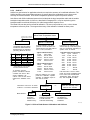
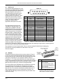
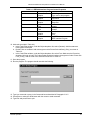
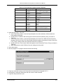
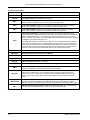
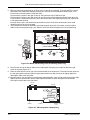
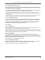
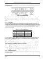
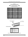
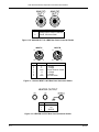
Lake Shore Model 340 Temperature Controller User’s Manual
CHAPTER 7
ANALOG OUTPUT, DIGITAL I/O,
ALARM, AND RELAY OPERATION
7.0 GENERAL
The Model 340 has several hardware features that enable it to interface with the experimental environment.
These hardware features defined the operation of the controller as related to temperature measurement and
control, but can also be controlled manually by the user from the front panel or over computer interface.
Analog outputs are described in Paragraph 7.1. Digital inputs and outputs (I/O) are described in Paragraph
7.2. Input alarms are described in Paragraph 7.3. Finally, high and low relays are described in Paragraph 7.4.
7.1 ANALOG OUTPUTS
The Model 340 has two analog outputs, Analog Output 1 and Analog Output 2. They are voltage sources that
can be used to output a voltage representation of sensor input reading. Analog Output 2 can also be used as
the control output for Loop 2 as described in Paragraph 7.1.3. The user can select the source of the analog
output data and scale the relationship of data reading to output voltage, independently for the two analog
outputs.
The analog outputs are variable DC voltage sources that can vary from ±10 V. The resolution of the analog
output is 1.25 mV or 0.0125% of full scale. The output can source up to 100 mA of current providing a
maximum of 1 W of power. They can drive a resistive load of no less than 100 Ω. The output is short
protected so the instrument is not harmed if the load resistance is too small. This is not recommended
because the additional load on the power supplies in the instrument causes noise on the internal circuits. The
analog output connector and pinouts are shown in Figure 10-5.
To set up an analog output, first
select an operating mode. Other
parameters depend on the mode
that is selected. A list of analog
output operating modes is shown
to the right.
OFF
INPUT
LOOP
MANUAL
Output voltage is set to 0 volts.
Analog output voltage is tied to a sensor input.
Control Loop 2 Control output (Analog Output 2 only).
Manual setting of the analog output voltage.
To select an analog output mode, press the Analog Outputs key. The ANALOG OUTPUTS screen is
displayed. With the output number highlighted in the top left corner, use the s or t key to select an analog
output. Press the Next Setting key until the Mode field is highlighted. Use the s or t key to select the
desired mode. Press the Next Setting or Enter key to make changes to other parameters, or press the Save
Screen key to store the changes. The default setting is Off.
The analog output is capable of setting a bipolar (positive or negative) voltage. When the bipolar parameter is
on, the analog output varies between ±10 V. Many inputs may be damaged by a negative voltage. Setting the
bipolar parameter to off prevents the analog output from setting a negative output voltage. Only voltages
between 0 and +10 V are set. The bipolar setting is used for all of the analog output modes.
To set the bipolar parameter, press the Analog Outputs key. The ANALOG OUTPUTS screen is displayed.
With the output number highlighted in the top left corner, use the s or t key to select an analog output.
Press the Next Setting key until the bipolar field is highlighted. Use the s or t key to select ON or OFF.
Press the Next Setting or Enter key to make changes to other parameters or press the Save Screen key to
store the changes. The default setting is Off.
Analog, Digital, Alarm & Relay Operation
7-1