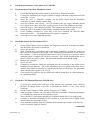
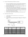
1
paraPAC P2/2D/22D
ON-SITE
MAINTENANCE PROCEDURE
LEVEL ONE: PERIODIC PERFORMANCE CHECKS
Pneupac Ltd.© 2002
Part No. 504-2004
Issue 5h March 2002
Pneupac Ltd
Bramingham Business
Park
Enterprise Way
Luton
Bedfordshire LU3 4BU
CONTENTS
Contents
Page 1
SECTION ONE
Pages 3-4
Important General Information
Safety Procedures-medical gas cylinders
SECTION TWO
Pages 5-6
Service/Test Schedule
SECTION THREE
Pages 7-15
Service/Test Procedure
SECTION FOUR
Page 17-18
Spare Parts List
Special Equipment
©
This procedure is the property of Pneupac Ltd. Copyright for all purposes is vested in Pneupac.
The reproduction of this procedure in whole or in part is prohibited without express consent in writing.
This procedure is offered for use only with equipment manufactured or specifically recommended
Pneupac. Rights are reserved to make a charge for the use of this procedure or any part thereof and
such right shall subsist unless and until the same shall be expressly waived in writing. Acceptance of
this document will be construed as acceptance of these conditions.
504-2004 Iss 5h
1
Mar 2002
INTENTIONALLY BLANK
504-2004 Iss. 5h
2
Mar.2002
IMPORTANT GENERAL INFORMATION
SECTION ONE
a) General
The safety precautions given in this section are to be seen as a guide only and are not intended to
be a comprehensive list.
i) Qualified persons
Persons servicing and repairing Pneupac ventilators and regulators must be adequately trained and
certified by the manufacturer for this task and must be fully conversant with the relevant contents of
the User's Manual supplied with the equipment. Engineers must perform service repair and testing of
equipment in line with both Health and Safety at Work regulations and their own employer’s
procedures and observe the appropriate precautions necessary when handling pressurised gases.
This Maintenance Procedure should be read fully before commencing servicing and testing.
ii) Frequency Checking
Regular performance checking of the paraPAC ventilator must be carried out with equipment
calibrated to ensure accuracy under the flow patterns generated by the ventilator.
The user should determine the frequency of periodic checks dependent upon the intensity of use.
Normally this would be not more often than once every 6 months but at least once every 2 years.
iii) Oxygen Safety
WARNING: Oil, grease or combustible lubricants, other than those approved for oxygen
service, must never be allowed to come into contact with the parts of the ventilator,
oxygen regulator, cylinder, repair tools or repair surfaces used in the servicing of this
equipment. Particular care should be taken to avoid any trace of contamination around
the oxygen inlet and outlet ports of the ventilator. Oil or Grease oxidise readily and in
the presence of oxygen will burn violently.
Regulator assemblies must not be immersed in liquid at any time.
iv) Note to Service Engineers
It is the responsibility of the customer to present the equipment in a fit condition for use and therefore
servicing (if this is not your responsibility). This should enable you to quickly assess the condition of
the equipment overall and any obvious damage.
v) MRI
When the ventilator is being used/or likely to be used in an MR Environment, it is important
that only MR Compatible spares or accessories are used. This must be checked as part of the
on- site maintenance procedure.
vi) CE Marking
Some of the ventilators described in this manual carry a CE mark to certify that they have been
manufactured to conform to the requirements of the European Medical Devices Directive 93/42/EEC.
To ensure that this equipment is maintained to the requirements of the Directive only accessories,
ancillaries and spares authorised by the manufacturer should be fitted. All such parts sold by Pneupac
have /CE incorporated in their order code. Parts that are not marked with /CE are only for sale as
spares for pre- CE ventilators.
504-2004 Iss 5h
3
Mar 2002
b) SAFETY PROCEDURES - MEDICAL GAS CYLINDERS
1)
The warnings on the previous page relating to the use of oxygen are particularly
relevant to gas cylinders and cylinder pressure regulators.
2)
All personnel handling medical gas cylinders should have adequate knowledge of the
properties of the gas, precautions to be taken and the correct operation of the
equipment.
3)
Check the cylinder for the name of the gas and the colour code to ensure that the
correct cylinder is being used.
4)
Before using a cylinder check it and its valve are in good condition. If there appears to
be any damage do not use it.
5)
All cylinders are fitted with a colour-coded ring on the valve stem showing when it is
due for inspection or test. Check that the cylinder is within date. If not do not use it.
6)
Completely remove the plastic seal from the valve. Open the valve momentarily to
blow any contamination out of the valve outlet. Ensure that the outlet is not directed
towards any person.
7)
Ensure that the connecting faces on the cylinder and the regulator or fitting are clean
and free from scoring or damage.
8)
The regulator or fitting can now be attached, using only a reasonable amount of effort
to tighten the connection. Never use a hammer or lever.
9)
Always open the cylinder slowly.
10)
Always close the cylinder fully before disconnecting a cylinder and fit a cap or tape to
the cylinder valve outlet to keep it clean.
504-2004 Iss. 5h
4
Mar.2002
SECTION TWO
TEST SCHEDULE FOR PERIODIC CHECKING OF
paraPAC P2/2D/22D
1.
Report Details
2.
Check condition of Carry Case.
3.
Check condition of Regulator Assembly
4.
Check condition of cylinder key.
5.
Check Regulator output.
6.
Check condition of Input Hose.
7.
Check condition of the paraPAC.
8.
Check condition of patient hose.
9.
Check condition of patient valve.
10.
Check the performance of the paraPAC
10.1
Check function of On/Off switch.
10.2
Check function of Air Entrainment NRV.
10.3
Check the CMV/Demand function (2D model only).
10.4
Check Frequency with no air mix.
10.5
Check Frequency with air mix.
10.6
Check Tidal volume with no air mix.
10.7
Check Tidal volume with air mix.
10.8
Check relief pressure/audible alarm with no air mix.
10.9
Check relief pressure/audible alarm with air mix.
10.10 Check O2 concentration with air mix
11.
Check the output from the Nebuliser output on P22D.
(continued)
504-2004 Iss 5h
5
Mar 2002
TEST SCHEDULE FOR PERIODIC CHECKING OF
paraPAC P2/2D/22D (continued)
12.
Check Oxygen Therapy unit.
13.
Check condition of face masks (child and adult) and sterile packed airways.
14.
Check contents of customer cylinder.
15.
Check User Handbook.
16.
Record repairs and replacements.
504-2004 Iss. 5h
6
Mar.2002
SECTION THREE
PROCEDURE FOR PERIODIC CHECKING OF paraPAC P2/2D/P22D
1.
Record the serial number and model of the paraPAC and, where applicable, the serial
number on the regulator assembly body. Using the Pneupac datecode chart, check if the
regulator assembly requires the recommended 4 - 5 year complete disassembly service
(refer also to Maintenance Manual 504-2008 for High Pressure Regulator Assembly).
2.
Check condition of Carry Case
i)
ii)
iii)
iv)
v)
vi)
3.
Check case lids as they can tear on hinges due to mishandling.
Check wooden stiffeners in side panels for rigidity.
Check elastic and Velcro strapping for condition and security.
Check case exterior for signs of splitting or wear along the edges.
Check all carry handles and straps for security, tears and missing fittings.
Check all zips for security and operation.
Check condition of Regulator Assembly
i)
The warnings in Section One relating to the use of oxygen are particularly relevant to
gas cylinders and cylinder pressure regulators.
ii)
Check that the cylinder valve is closed and the regulator assembly is de-pressurised.
iii)
Disconnect the equipment probes from the regulator assembly.
iv)
Release the T-handle slowly and remove the regulator assembly from cylinder.
v)
Check that the T-handle is straight, undamaged and screws in and out freely.
vi)
Check that the T-handle retaining circlip is in position.
vii)
Check that the hexagonal nut on the pin-index yoke is tight.
viii) Ensure that the gas indexing pins are in position and are secure.
ix)
From June 1997 a sintered filter has been fitted into the end of the pin-index yoke
nipple. Check that this filter (where fitted) is clean and not blocked. (The filter may be
replaced as described in Section 4 of the Maintenance Manual (504-2008) for High
Pressure Regulator Assembly).
x)
Check the gas specific outlet connector and assembly for slackness and tighten if loose.
xi)
Check that the relevant probe fits correctly into the connector.
xii)
Check that the gauge is not loose and has not been bent in relation to the regulator.
xiii) Inspect the gauge for visible damage front and back. Ensure that the gauge indicator
needle is positively against the zero position stop.
xiv) Check that the gauge is fully protected by its rubber shroud and that the shroud is not
damaged.
xv)
Check that the two rubber blow-out discs in the over-pressure relief ports are in place in
the regulator body.
xvi) On CE regulators check that the secondary relief valve on the corner of the regulator
block is not damaged or blocked. If damage is evident the regulator must be changed.
xvii) If a Constant Flow Selector Head is fitted check the condition, looking for damage to
the head and/or the outlet connector.
xviii) Check that the head is securely fastened to the regulator manifold.
xix) Check that the Constant Flow Selector Head clickstop mechanism is effective.
xx)
Check that any movement between the pin-index yoke and the regulator assembly
disappears when the assembly is attached to a cylinder.
504-2004 Iss 5h
7
Mar 2002
4.
Check condition of cylinder key
i)
ii)
5.
Replace if cracking is apparent.
Check attachment cable is not frayed or damaged. Replace if necessary.
Check Regulator output
i)
ii)
iii)
iv)
v)
vi)
vii)
viii)
ix)
x)
xi)
Fit a new seal (500-276) to the Regulator Assembly.
Connect the pin-index yoke to a cylinder at least three quarters full.
Connect the Test Unit to the outlet connector of the Regulator Assembly.
Ensure that the Test Unit output is pointed away from the operator and that the flow/noflow switch is in the ‘Off’ (no-flow) position. Open the cylinder valve slowly allowing
gas into the regulator and the Test Unit. With no flow the pressure gauge on the Test
Unit will show the static output pressure of the regulator. Record this pressure which
should be between 50 - 80 psi (345-552 kPa).
Slide the flow/no-flow switch to the ‘On’ (flow) position. This allows gas to flow
through the regulator and out of the Test Unit. The pressure gauge on the Test Unit
now shows the dynamic output pressure of the regulator. Record the result and switch
off the flow as soon as the reading is noted. This dynamic pressure will be lower than
the previous static pressure but should be no less than 45 psi (310 kPa).
Re-check the static pressure reading and in particular check that it does not creep
continuously higher such that it eventually exceeds the upper allowed pressure of 80 psi
(552 kPa). If the pressure continues to creep upwards the main valve seat is leaking
and the regulator needs corrective servicing.
The above procedure should be repeated using a cylinder not more than a quarter full.
Close the cylinder valve. The contents gauge should maintain a constant reading.
If the pressure decays at a visible rate, a leak is occurring and corrective servicing is
required.
Vent the pressure by sliding the Test Unit switch to the ‘On’ position and then remove
the Test Unit.
Re-open the cylinder valve slowly, observe the contents gauge, then close the cylinder
valve. The gauge should maintain a constant reading. If the pressure decays at a
visible rate the outlet connector/s may be leaking and need corrective servicing.
Where a Constant Flow Selector Head is fitted (500-A947 or 500-A958) check the
performance as follows:
(a)
Connect a calibrated flowmeter (e.g. 2-25 L/min; 500-82636) to the outlet
connector of the Flow Head.
(b)
Using the table below check performance of the Flow Head across the range:
Set Flow L/min
2
5
10
15
xii)
504-2004 Iss. 5h
Actual flow L/min
1.8 – 2.2
4.5 – 5.5
9.5 – 10.5
14.5 – 15.5
Replace the Regulator Assembly if any of the above checks fail or repair as
detailed in the High Pressure Regulator Assembly On-Site Routine Service
Procedure (504-2008).
8
Mar.2002
Figure 1
3 (xiv
3. (iii - (viii
3 (xv
4 (i & (ii
3 (xiv - (xviii
3 (xi - (xiii
3 (ix & (x
Figure 2
Regulator Test Unit 500-A615
Figure 3
Regulator Test Unit 500-A615
on 500-A162 regulator
504-2004 Iss 5h
9
Mar 2002
6.
Check condition of the Input Hose
i)
ii)
iii)
iv)
v)
7.
From 1st January 2002 pressure hoses are date coded and should be replaced after 6
years use. Check the label on hose for replacement date.
Check that there is no internal damage to the hose by feeling the rigidity of the hose
and looking for sloppiness.
Ensure there is no delamination of the hose and no blisters or bubbles on the surface
(check again when the hose is pressurised).
Check union ends for signs of kinking and/or damage to hose or union.
Replace hose if any of above is apparent.
Check the condition of the paraPAC
i)
ii)
iii)
iv)
v)
vi)
vii)
Check the ventilator looking for damage to the gas input and output fittings, the gauge
and gauge surround, the gas supply indicator (on CE ventilators only), the control
knobs, the case and the labels. On the P22D check the Nebuliser outlet connection is
not blocked and the manufacturers plug is still attached to the ventilator casing. On
ventilators fitted with the EP Option check that the manometer connection is secure and
is not blocked.
Check that the sintered filter in the input connector is clean and not obscured. Change
the input connector and/or filter if the filter is dirty. To change the filter, first remove
the connector and seal from the ventilator. The filter can be replaced by removing the
O-ring (W5520). The conical filter (W9151) should now be pushed from the
connector. Both O-ring and filter should be replaced. Refit the connector with a new
sealing washer (W5783).
Check that the input and output connectors are secure. Tighten if necessary.
Check that the control knobs move smoothly, are not loose on the spindles and do not
rub on the front panel. If the spindles are bent the knob may rub on the front panel on
one side only and the needle cartridge may be damaged.
Rotate each control knob to its extreme limits to verify that the knob has not moved on
the spindle.
a)
The Frequency control knob should align with both ends of the calibration
marks, i.e. at 8 bpm and 40 bpm but should also engage the click stop position
at 12 bpm.
b)
The Tidal Volume control knob should align with both ends of the coloured
indicator band.
c)
The dot on the On/Off (CMV/Demand) knob should align with the calibration
marks and there should be no intermediate position.
d)
The dot on the Air Mix/No Air Mix knob should align with both indicated
positions with no intermediate position. The knob should click into position at
the No Air Mix position and spring back to the Air Mix position when released
from the click position.
e)
The Variable Relief knob should align with the calibration marks at each end of
the scale.
If the index mark on any knob side or end cap is misaligned it must be corrected before
further calibration checks are carried out.
To relocate the Frequency and Tidal Volume control knobs, remove the end cap from
the knob.
(continued)
504-2004 Iss. 5h
10
Mar.2002
7.
Check the condition of the paraPAC (continued)
viii)
ix)
x)
xi)
xii)
xiii)
xiv)
xv)
8.
Check the Condition of the Patient Hose
i)
ii)
iii)
iv)
v)
9.
Using an appropriate knob collet spanner (e.g. Pneupac 500-82073), release the knob
from the spindle.
a)
For the Frequency control knob, rotate the spindle until it engages the click-stop
position and set the indicator line on the knob at 12 bpm. Ensure that the knob
has a clearance of 0.5mm from the front panel and retighten. Check that the
knob aligns at the 8 bpm and 40 bpm positions respectively.
b)
For the Tidal Volume control knob rotate the spindle fully anticlockwise till it
reaches the stop and set the indicator line on the knob align with the end of the
coloured band. Ensure that the knob has a clearance of 0.5mm from the front
panel and retighten. Rotate the knob and check that it aligns with the opposite
end of the band.
Refit the knob cap ensuring the line on the cap aligns with the line on the knob.
The On/Off (Demand/CMV-Demand), the Air Mix/No Air Mix switch and the Variable
relief switch knobs have a fixed position but the end cap can be relocated on the front
of the knob to give correct indication.
If the caps on the above knobs have been removed for relocation or can be rotated,
relative to the knob, during normal operation they should be secured to the knob with a
very small drop of adhesive (DS354 C10/Loctite Prism 460).
Check that the gauge surround is secure, the front panel label is secure and not
damaged (i.e. punctured).
Check that the gauge is in the correct vertical position and has not rotated in the shroud.
Replace any damaged labels.
Check that any accessories or spares added are MR Compatible where applicable.
Check the Patient Hose for damage, splits or small holes in the corrugated tube.
If any defect is found replace the hose tube immediately.
For EP Option circuits check that a complete circuit is available and that the sensing
line has no defects.
Check that the adaptor at the Patient Valve end of the circuit is undamaged, fits closely
onto the Patient Valve and the sensing line connecting spigot is not damaged.
Replace the filter (W7085) in the EP Option sensing line.
Check the Condition of the Patient Valve
i)
ii)
iii)
iv)
v)
504-2004 Iss 5h
Check the Patient Valve assembly for cracks, splits and scoring to the connection faces.
Disassemble the Patient Valve by unscrewing the two parts of the body and carefully
remove the valve element (lip membrane). Inspect the element by gently stretching,
looking for splits or tears. Replace if necessary.
Carefully remove the annular disc surrounding the patient connector (paraPAC 2D/22D
only). Inspect the element as ii) above. Replace if necessary.
Reassemble the Patient Valve ensuring that the valve element is inserted the correct
way round and that the annular disc is correctly seated.
Recommend replacement if necessary.
11
Mar 2002
10.
Check the performance of the paraPAC P2/2D/22D
10.1
Check function of the Main Pneumatic Switch
i)
ii)
iii)
iv)
v)
vi)
vii)
viii)
10.2
Check function of Air Entrainment N.R.V.
i)
ii)
iii)
iv)
v)
vi)
vii)
10.3.
Check that the Main Pneumatic switch is in the 'Off' or 'Demand' position.
Connect the ventilator to an oxygen cylinder or supply (minimum requirement 60L/min
at 305 kPa ? 3 bar).
Select the ‘Off’ or ‘Demand’ position. On the P22D ensure that the humidifier
connection is sealed with the captive plug.
Open the cylinder valve slowly. On CE ventilators the gas supply indicator should
now change from red to white if the supply pressure is above the minimum specified.
Select the 'On' or 'CMV Demand' position. The ventilator should now begin to cycle.
Select the 'Off' or 'Demand' position and the ventilator should stop cycling.
If the ventilator continues to cycle after it has been switched off, then the Main
Pneumatic switch
is leaking and must be repaired or replaced.
Select the 'On' or CMV/Demand' position.
Set the Tidal Volume control to 200mL, the Frequency control to 25 breaths per minute
and the Relief valve knob to maximum.
Select 'No Air Mix'.
With a Patient hose and patient valve connected* completely occlude the outlet port
and note the movement of the needle on the Inflation Pressure Monitor on the front of
the ventilator. (*This is particularly important for the EP option as no pressure will be
indicated unless a complete EP circuit is connected.) The needle should rapidly rise to
the 80 x100Pa (80 cmH2 O) mark. The pneumatic audible alarm should sound.
Remove the occlusion.
Select 'Air Mix'.
Completely occlude the outlet port and again note the movement of the needle on the
Inflation Pressure Monitor. The needle should this time rise rapidly at first then slower
until the 80 x100Pa (80 cmH2 O) is reached but with one smooth action. The pneumatic
alarm should again operate as in 10.2 iii).
If the needle rises jerkily to the 80 x100Pa (80 cmH2 O) mark, there is a fault within the
air entrainment NRV.
Check the CMV/Demand Function (2D/22D only)
i)
ii)
iii)
iv)
v)
504-2004 Iss. 5h
Connect a test mask to the outlet port of the patient valve preferably using a Heat &
Moisture Exchange Filter to provide a contamination barrier, or use a test circuit
complete.
Set the Tidal Volume to 800mL and the Frequency to 12 BPM.
After giving the ventilator 4 to 5 breaths to settle down, demand a breath approximately
1.5 seconds long at the end of the inspiratory phase.
There should be a short delay and then the ventilator should deliver a second breath.
Continue to demand full breaths on the ventilator at a rate faster than 12 BPM, which
should inhibit the automatic cycling.
Stop demanding breaths from the ventilator and it should begin to auto cycle after the
correct expiratory time has elapsed.
(continued)
12
Mar.2002
10.3.
Check the CMV/Demand Function (2D/22D only) (continued)
vi)
Repeat the test but gradually reduce the size of each breath whilst maintaining the rate.
The ventilator should continue to inhibit until the breath taken is too small in flow or
short in time to inhibit. At this point the ventilator should restart auto cycling.
Repeat the test again but this time using short ‘panting’ breaths. The ventilator should
ignore these and continue cycling.
Select the 'Off' or 'Demand' position. Now demand a breath from the ventilator. The
Demand Valve should now supply oxygen to the Patient Valve.
Close the cylinder or supply and continue to demand breaths. The breathing resistance
will increase. When the supply is depleted, on CE ventilators, the gas supply indicator
should change from white to red and the internal spontaneous breathing valve should
open. There should be a slight increase in breathing resistance as air is drawn through
the spontaneous breathing valve from atmosphere.
Remove the patient circuit, patient valve and mask. If an HMEF was not used, clean
the patient valve as instructed in the User’s Manual.
Open the cylinder or supply slowly. The gas supply indicator should change to white.
vii)
viii)
ix)
x)
xi)
10.4
Check Frequency with No Air Mix
i)
Connect a Pneupac ratePAC and backpressure device to the outlet port of the
ventilator module.
Select ‘No Air Mix’.
Using the table below to set the controls, check the frequency of the ventilator across
the whole range ensuring that the backpressure is maintained at 15 x100Pa (15
cmH2 O).
ii)
iii)
V Tdel
(mL)
Frequency
Set (bpm)
Frequency
(tolerance)
1300
1000
800
500
8
12
15
20
25
30
35
40
6.8 – 9.2
10.2 – 13.8
12.7 – 17.3
17.0 – 23.0
21.25 – 28.75
25.5 – 34.5
29.75 – 40.25
34.0 – 46.0
200
504-2004 Iss 5h
13
Respiratory
Time (secs)
7.5
5.0
4.0
3.0
2.4
2.0
1.71
1.5
Respiratory Time
(tolerance)
8.82 – 6.52
5.88 – 4.35
4.72 – 3.47
3.53 – 2.61
2.82 – 2.12
2.35 – 1.74
2.02 - 1.49
1.76 – 1.30
Mar 2002
10.5
Check Frequency with Air Mix
i)
ii)
iii)
10.6
With the ratePAC and backpressure device still fitted, select ‘Air Mix’.
Repeat instruction 10.4. iii).
Remove the ratePAC and reconnect the backpressure device.
Check Tidal Volume, with No Air Mix
i)
ii)
Connect a calibrated respirometer to the outlet port of the backpressure device.
Set a backpressure (as the table below and the Pneupac date code chart) depending on
the model and year of manufacture of the ventiPAC.
Pre February 1992
=
Post February 1992 =
Post December 1992 =
iii)
iv)
Select ‘No Air Mix’.
Using the table below to set the controls and the calibration chart for the
respirometer, check the tidal volume of the ventilator across the whole range. Note
the respirometer serial number.
V Tdel
(mL)
1300
1000
500
10.7
No back pressure
10 x100Pa (10 cmH2 O) back pressure
15 x100Pa (15 cmH2 O) back pressure
Frequency Set
(bpm)
8
12
20
Tidal Volume Actual
(tolerance)
1268 – 1682
851 – 1129
404 - 536
Check Tidal Volume with Air Mix
i)
ii)
iii)
504-2004 Iss. 5h
With the calibrated respirometer and the backpressure device still connected to the
outlet port, select the ‘Air Mix’ position.
Repeat instructions 10.7 iii) and iv).
Remove the respirometer.
14
Mar.2002
10.8
Check Relief Pressure and Audible Alarm with No Air Mix
i)
ii)
10.9
Select ‘No Air Mix’ and set the Frequency control to its minimum.
Using the table below, check the relief pressure and audible alarm of the ventilator
across the whole range. At each setting temporarily close the backpressure device. The
pneumatic audible alarm should sound.
V Del set
Pressure Relief (set)
Pressure Relief (actual)
200
1300
800
800
200
1300
20
20
40
60
80
80
>12
< 28
32 – 48
48 – 72
> 68
< 92
Check Relief Pressure and Audible Alarm with Air Mix
i)
ii)
Select ‘Air Mix’.
Repeating the instructions as in 10.8, check the relief pressure and the audible alarm of
the ventilator as set below.
V Del set
200
Pressure Relief (set)
20
Pressure Relief (actual)
>12
10.10 Check Oxygen Concentration with Air Mix
i)
ii)
iii)
iv)
v)
504-2004 Iss 5h
Switch on the oxygen monitor and check reading is 21%. Recalibrate the monitor with
100% oxygen if necessary (at least once every 8 hours).
Connect the oxygen monitor to the outlet port of the ventilator
Select ‘Air Mix’.
Set a frequency of 12 breaths per minute.
Using the table overleaf check the oxygen concentration of the delivered gas.
15
Mar 2002
(continued)
10.10 Check Oxygen Concentration with Air Mix (continued)
V Del Set
(mL)
1300
500
v)
11.
ii)
iii)
iv)
v)
Select the 'Off' or 'Demand' position and the ventilator should stop cycling.
Remove the plug from the Nebuliser connection and connect a calibrated 0-100 psi
gauge to the connection.
Set the Frequency control to 8 bpm and the Flow control to maximum.
Select the ‘On’ or ‘CMV/Demand’ position.
Check that the pressure on the gauge rises to a minimum of 29 psi during inspiration
and that the pressure decays towards zero during expiration.
Refit the plug or reconnect the Nebuliser Circuit.
Check the performance of the Oxygen Therapy Unit (500-A253 or 500-A253/CE)
i)
ii)
iii)
iv)
v)
vi)
13.
44 - 50
44 - 50
Check the output from the Nebuliser connection on paraPAC P22D
i)
12.
Permissible % O2 Concentration
Check the Therapy lead and mask/s for signs of damage.
Identify the lead capacity marked on a sleeve affixed to the lead.
Remove the ventilator probe from the Regulator Assembly and insert the Therapy lead
probe.
Connect the lead to a calibrated flowmeter (e.g.500-82636 2 - 25 L/min).
Open the cylinder valve and check the oxygen flow from the lead is correct
(+10% / -5%).
Close the cylinder valve and remove the Therapy lead probe from the regulator
assembly.
Check the condition of facemasks (child and adult) and sterile packed airways
i)
ii)
iii)
iv)
504-2004 Iss. 5h
Check the facemask/s for damage and splits.
Check that the mask/s fit properly onto the 22mm taper of the Patient Valve.
Check the packaging and sterile expiry date of Guedel airways.
Recommend replacement as necessary.
16
Mar.2002
14.
Check contents of customer cylinder
i)
ii)
iii)
15.
During testing do not use the gas cylinder in the set being tested.
Check that the cylinder is not empty and note the contents. Advise if the cylinder
content is low.
Record the date on the ring around the cylinder valve indicating when the cylinder
retest is required and advise if that date is approaching.
Check User Handbook.
Check the User’s Handbook supplied with the set is present and in good condition.
If missing recommend replacement.
16.
Record repairs and replacements. Obtain an acceptance signature on the Service Record
sheet.
504-2004 Iss 5h
17
Mar 2002
INTENTIONALLY BLANK
504-2004 Iss. 5h
18
Mar.2002
SECTION FOUR
SPARE PARTS FOR paraPAC P2/2D/22D
NOTE: for CE paraPACs please follow the part number in the list below with ‘/CE’
Part No.
Description
500-A4518
W9151
W5520
W5783
W7149
Input fitting assembly
Sintered Filter
Retaining O-ring for sintered filter
Sealing Washer
CMV/Demand, Relief Pressure,
Air Mix/No Air Mix Control Knob
CMV/Demand, Air Mix/No Air Mix,
Control Knob End Cap
Relief Pressure Control Knob End Cap
Frequency or Tidal Volume Control Knob
Frequency or Tidal Volume Control Knob End Cap
Box Bungs (Caps)
Audible Alarm
Guedel Airway Size 00
Guedel Airway Size 0
Guedel Airway Size 1
Guedel Airway Size 2
Guedel Airway Size 3
Comprehensive Carrying Case
W7150
W7151
W7152
W7153
500-4810
300-9377
W6873
W6874
W6875
W6876
W6877
500-A177
504-2004 Iss 5h
500-A162
500-A162/Z43
Pin-index regulator assembly with single Schrader Outlet
Pin-index regulator assembly with single Schrader Outlet with
Constant Flow Selector Valve
500-A4981
500-A254/6
W6882
W6807
W6806
W6803
W6804
500-A171
500-276/3
W7130
W7486
510A2667
510A2668
Lead Input - /4 "BSP /Schrader
Lead O2 Therapy (Schrader)
Mask O2 Therapy- Pack 5
Mask, Adult Clear
Mask, Child/Small Adult
Mask, Paediatric Size 0
Mask, Paediatric Size 1
Wheel, Valve Cylinder
Washers Pin Index (3)
Patient Hose
Patient Hose - Silicone
Patient Valve for Model 2D/22D
Patient Valve for Model 2
1
19
Mar 2002
SPARE PARTS FOR paraPAC P2/2D/22D (continued)
Part No.
510A1584
510A1582
510A1591
W6894
1025U-04-01/350mm
510A2666
510A1768
510-A1619
W7541
W7213
Description
Complete Nebuliser Set for P22D
Nebuliser Assembly
4mm Plug
Water Reservoir
4mmPolyurethane tube
Complete EP Option Circuit
Filter Kit
Patient Valve Adaptor
Sensing Line
Clip
SPECIAL EQUIPMENT FOR PERIODIC CHECKING OF
paraPAC P2/2D/22D
Part No.
Description
500-A615
Regulator Test Rig (Schrader)
510-A1541
Pneupac ratePAC
500-A82803
Pneupac Back Pressure Device with 0-100cmH O Pressure gauge
2
(calibrated)
504-2004 Iss. 5h
500-82633
0-100 PSI Gauge (calibrated)
500-82802
Respirometer (Pneupac calibrated)
POM 60
Oxygen Monitor
500-82073
Knob Collet Spanner
20
Mar.2002