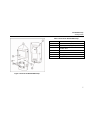
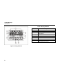
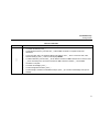
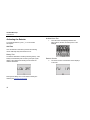
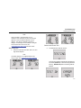
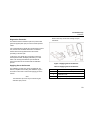
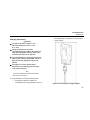
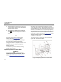
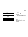
1
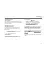
GasAlertMicroClip
H2S, CO, O2, Combustibles
1, 2, 3, and 4 Gas Detectors
User Manual
D5908/2 English
iERP: 124291
© BW Technologies 2007, all rights reserved. Printed in Canada.
All product names are trademarks of their respective companies.
Limited Warranty & Limitation of Liability
BW Technologies LP (BW) warrants this product to be free from defects in material and workmanship under normal use and service for a period of two years,
beginning on the date of shipment to the buyer. This warranty extends only to the sale of new and unused products to the original buyer. BW’s warranty
obligation is limited, at BW’s option, to refund of the purchase price, repair, or replacement of a defective product that is returned to a BW authorized service
center within the warranty period. In no event shall BW’s liability hereunder exceed the purchase price actually paid by the buyer for the Product.
This warranty does not include:
a) fuses, disposable batteries or the routine replacement of parts due to the normal wear and tear of the product arising from use;
b) any product which in BW’s opinion, has been misused, altered, neglected or damaged by accident or abnormal conditions of operation, handling or use;
c) any damage or defects attributable to repair of the product by any person other than an authorized dealer, or the installation of unapproved parts on the
product; or
The obligations set forth in this warranty are conditional on:
a) proper storage, installation, calibration, use, maintenance and compliance with the product manual instructions and any other applicable
recommendations of BW;
b) the buyer promptly notifying BW of any defect and, if required, promptly making the product available for correction. No goods shall be returned to BW
until receipt by the buyer of shipping instructions from BW; and
c) the right of BW to require that the buyer provide proof of purchase such as the original invoice, bill of sale or packing slip to establish that the product is
within the warranty period.
THE BUYER AGREES THAT THIS WARRANTY IS THE BUYER’S SOLE AND EXCLUSIVE REMEDY AND IS IN LIEU OF ALL OTHER WARRANTIES,
EXPRESS OR IMPLIED, INCLUDING BUT NOT LIMITED TO ANY IMPLIED WARRANTY OF MERCHANTABILITY OR FITNESS FOR A PARTICULAR
PURPOSE. BW SHALL NOT BE LIABLE FOR ANY SPECIAL, INDIRECT, INCIDENTAL OR CONSEQUENTIAL DAMAGES OR LOSSES, INCLUDING LOSS
OF DATA, WHETHER ARISING FROM BREACH OF WARRANTY OR BASED ON CONTRACT, TORT OR RELIANCE OR ANY OTHER THEORY.
Since some countries or states do not allow limitation of the term of an implied warranty, or exclusion or limitation of incidental or consequential damages, the
limitations and exclusions of this warranty may not apply to every buyer. If any provision of this warranty is held invalid or unenforceable by a court of competent
jurisdiction, such holding will not affect the validity or enforceability of any other provision.
BW Technologies by Honeywell
Corporate Headquarters
2840 – 2nd Ave. SE
Calgary, AB
Canada T2A 7X9
BW Technologies by Honeywell
America
3279 West Pioneer Parkway
Arlington, TX
USA 76013
BW Technologies by Honeywell
Europe
5 Canada Close
Banbury, Oxfordshire
UK OX16 2RT
Table of Contents
Title
Page
Introduction............................................................................................................................................ 1
Contacting BW Technologies by Honeywell ......................................................................................... 2
Safety Information - Read First ............................................................................................................. 2
Getting Started ...................................................................................................................................... 6
Activating the Detector ........................................................................................................................ 10
Self-Test ...................................................................................................................................... 10
Self-Test Pass ............................................................................................................................. 15
Self-Test Fail ............................................................................................................................... 15
Battery Test ................................................................................................................................. 15
Backlight ...................................................................................................................................... 16
Deactivating the Detector.................................................................................................................... 16
Options ................................................................................................................................................ 16
Detector Identification.................................................................................................................. 17
Sensor Options............................................................................................................................ 17
User Options Menu ..................................................................................................................... 20
Language Menu........................................................................................................................... 21
Alarms ................................................................................................................................................. 22
Computed Gas Exposures .......................................................................................................... 24
Viewing Gas Exposures .............................................................................................................. 25
Gas Alarm Setpoints ................................................................................................................... 26
Resetting Gas Alarm Setpoints ................................................................................................... 26
Stopping a Gas Alarm ................................................................................................................. 27
Sensor Alarm............................................................................................................................... 27
i
GasAlertMicroClip
User Manual
Title
Page
Low Battery Alarm .......................................................................................................................27
Automatic Shutdown Alarm .........................................................................................................27
Calibration ...........................................................................................................................................28
Guidelines....................................................................................................................................28
Diagnostics Protection.................................................................................................................29
Applying Gas to the Sensors .......................................................................................................29
Calibration Procedure..................................................................................................................30
Datalogs ..............................................................................................................................................34
Event Logs ..........................................................................................................................................34
Downloading Datalogs and Event Logs ......................................................................................34
Maintenance........................................................................................................................................34
Charging the Detector .................................................................................................................35
Replacing a Sensor or Sensor Filter ...........................................................................................36
Troubleshooting...................................................................................................................................39
Replacement Parts and Accessories ..................................................................................................42
Specifications ......................................................................................................................................43
General Datalogger Specifications..............................................................................................45
ii
List of Tables
Table Title
1.
2.
3.
4.
5.
6.
7.
8.
9.
10.
11.
12.
13.
Page
Gases Monitored ................................................................................................................... 1
International Symbols ............................................................................................................ 5
GasAlertMicroClip Detector ................................................................................................... 7
Display Elements ................................................................................................................... 8
Pushbutton............................................................................................................................. 9
Alarms.................................................................................................................................. 22
Computed Gas Exposures .................................................................................................. 24
Gas Alarm Setpoints............................................................................................................ 26
Sample Factory Alarm Setpoints ......................................................................................... 26
Applying Gas to the Sensors ............................................................................................... 29
Replacing a Sensor or Sensor Filter ................................................................................... 37
Troubleshooting Tips ........................................................................................................... 39
Replacement Parts and Accessories .................................................................................. 42
iii
GasAlertMicroClip
User Manual
iv
List of Figures
Figure Title
1.
2.
3.
4.
5.
6.
Page
GasAlertMicroClip Detector ................................................................................................... 7
Display Elements ................................................................................................................... 8
Applying Gas to the Sensors ............................................................................................... 29
Connecting the Charging Adapter ....................................................................................... 35
Replacing a Sensor or Sensor Filter ................................................................................... 36
Replacing the Rear Shell..................................................................................................... 38
v
GasAlertMicroClip
User Manual
CAUTION: FOR SAFETY REASONS, THIS EQUIPMENT
MUST BE OPERATED AND SERVICED BY QUALIFIED
PERSONNEL ONLY. READ AND UNDERSTAND
INSTRUCTION MANUAL COMPLETELY BEFORE
OPERATING OR SERVICING.
GasAlertMicroClip Multi-Gas Detector with User
Downloadable Datalogger and Event Log
Standard instrument is equipped with integral concussionproof boot, internal vibrator alarm, and provides full-time
continuous datalogging while the instrument is operating.
Data is saved to memory and can be downloaded by the
user via an IR device to a PC. Data is imported into standard
office software (Microsoft® Excel, Access, etc.). Wraparound
memory ensures the most recent data is always saved.
vi
GasAlertMicroClip
Table 1. Gases Monitored
Introduction
a Warning
To ensure your personal safety, read “Safety
Information” before you use the detector.
The GasAlertMicroClip gas detector (“the detector”) warns of
hazardous gas at levels above user-selectable alarm
setpoints.
The detector is a personal safety device. It is your
responsibility to respond properly to the alarm.
Gas Detected
Unit of Measure
Hydrogen sulfide (H2S)
parts per million (ppm)
Carbon monoxide (CO)
parts per million (ppm)
Oxygen (O2)
percent by volume (%)
Combustible gases (LEL)
Field selectable for:
a) percent of lower
explosive limit (% LEL)
b) percent by volume
methane 0-5.0% v/v
Table 1 lists the gases monitored.
1
GasAlertMicroClip
User Manual
Contacting BW Technologies by
Honeywell
To contact BW Technologies by Honeywell, call:
USA: 1-888-749-8878
Canada: 1-800-663-4164
Europe: +44 (0) 1295 700300
Other countries: +1-403-248-9226
Address correspondence to:
BW Technologies by Honeywell
Corporate office
2840 – 2 Avenue S.E.
Calgary, AB T2A 7X9
CANADA
Email us at: [email protected]
Visit BW Technologies by Honeywell’s web site at:
www.gasmonitors.com
ISO 9001
2
Safety Information - Read First
Use the detector only as specified in this manual, otherwise
the protection provided by the detector may be impaired.
International symbols used on the detector and in this
manual are explained in Table 2.
Read the Cautions on the following pages before using the
detector.
ec Note
This instrument contains a lithium polymer
battery. Do not mix with the solid waste stream.
Spent batteries should be disposed of by a
qualified recycler or hazardous materials
handler.
GasAlertMicroClip
Safety Information - Read First
aCautions
⇒ Warning: Substitution of components may impair Intrinsic Safety.
⇒ Caution: For safety reasons, this equipment must be operated and serviced by qualified personnel only. Read
and understand the user manual completely before operating or servicing.
⇒ Do not use the detector if it is damaged. Before you use the detector, inspect the case. Look for cracks or
missing parts.
⇒ If the detector is damaged or something is missing, contact BW Technologies by Honeywell immediately.
⇒ Use only sensor(s) specifically designed for your GasAlertMicroClip model. (See the section, Replacement Parts
and Accessories).
⇒ Calibrate the detector before first-time use and then on a regular schedule, depending on use and sensor
exposure to poisons and contaminants. BW recommends at least once every 180 days (6 months).
⇒ BW recommends to “bump test” the sensors, before each day’s use, to confirm their ability to respond to gas by
exposing the detector to a gas concentration that exceeds the alarm setpoints. Manually verify that the audible
and visual alarms are activated. Calibrate if the readings are not within the specified limits.
⇒ It is recommended that the combustible sensor be checked with a known concentration of calibration gas after
any known exposure to catalyst contaminants/poisons (sulfur compounds, silicon vapors, halogenated
compounds, etc).
⇒ The combustible sensor is factory calibrated to 50% LEL methane. If monitoring a different combustible gas in
the % LEL range, calibrate the sensor using the appropriate gas.
⇒ Caution: High off-scale readings may indicate an explosive concentration.
⇒ Only the combustible gas detection portion of this instrument has been assessed for performance by CSA
International.
3
GasAlertMicroClip
User Manual
aCautions
⇒ Protect the combustible sensor from exposure to lead compounds, silicones, and chlorinated hydrocarbons.
Although certain organic vapors (such as leaded gasoline and halogenated hydrocarbons) may temporarily
inhibit sensor performance, in most cases, the sensor will recover after calibration.
⇒ For use only in potentially explosive atmospheres where oxygen concentrations do not exceed 20.9% (v/v).
⇒ Any rapid up-scaling reading followed by a declining or erratic reading may indicate a gas concentration beyond
upper scale limit, which may be hazardous.
⇒ Calibrate only in a safe area that is free of hazardous gas.
⇒ Use only BW approved batteries for your GasAlertMicroClip model (see Specifications).
⇒ Charge the detector before first-time use. BW recommends the detector be charged after every workday.
⇒ Charge the GasAlertMicroClip using the recommended charging adapter only. Do not use any other charging
adapter. Failure to observe this precaution could lead to fire or explosion.
⇒ Extended exposure of the GasAlertMicroClip to certain concentrations of combustible gases and air may stress a
detector element, which can seriously affect its performance. If an alarm occurs due to high concentration of
combustible gases, recalibration should be performed, or if needed, the sensor replaced.
⇒ Do not test the combustible sensor’s response with a butane cigarette lighter; doing so will damage the sensor.
⇒ Do not expose the detector to electrical shock and/or severe continuous mechanical shock.
⇒ Do not attempt to disassemble, adjust, or service the detector unless instructions for that procedure are
contained in the manual and/or that part is listed as a replacement part. Use only BW Technologies by Honeywell
replacement parts.
⇒ The detector warranty will be voided if customer, personnel, or third parties damage the detector during repair
attempts. Non-BW Technologies by Honeywell repair/service attempts void this warranty.
4
GasAlertMicroClip
Safety Information - Read First
Table 2. International Symbols
Symbol
Meaning
n
Approved to both U.S. and Canadian Standards by CSA - International
g
European Explosives Protection
X
Conforms to European Union Directives
ATEX
Conforms to European ATEX Directives
IECEx
International Electrotechnical Commission Scheme for Certification to Standards for Electrical Equipment for
Explosive Atmospheres
5
GasAlertMicroClip
User Manual
Getting Started
The list below provides the standard items included with your
detector. If the detector is damaged or something is missing,
contact the place of purchase immediately.
To order replacement parts, see the section Replacement
Parts and Accessories.
The detector comes with sensors and rechargeable battery
installed. If the battery needs to be replaced, contact BW
Technologies by Honeywell. If any of the sensors or the
sensor filter needs to be replaced, refer to Replacing a
Sensor or Sensor Filter.
•
Sensors: H2S, CO, O2, and combustible (LEL);
•
Calibration hose and cap;
•
Charging adapter;
To become familiar with the features and functions of the
detector, study the following figures and tables:
•
Quick reference guide;
•
•
Quick reference operations key; and
Figure 1 and Table 3 describes the detector’s
components.
•
CD.
•
Figure 2 and Table 4 describes the detector’s display
elements.
•
Table 5 describes the detector’s pushbutton.
6
GasAlertMicroClip
Getting Started
Table 3. Parts of the GasAlertMicroClip
Item
Description
1
Visual alarm bars (LED)
2
Liquid crystal display (LCD)
3
Audible alarm
4
Sensors
5
Pushbutton
6
Charging connector / IR interface
7
Alligator clip
Figure 1. Parts of the GasAlertMicroClip
7
GasAlertMicroClip
User Manual
Table 4. Display Elements
Item
Figure 2. Display Elements
8
Description
1
Alarm condition
2
Automatically span sensor
3
Gas cylinder
4
Gas identifier bars
5
Battery life indicator
6
Stealth mode
7
Numeric value
8
Automatically zero sensor
GasAlertMicroClip
Getting Started
Table 5. Pushbutton
Pushbutton
C
Description
•
To activate the detector press C.
•
To deactivate the detector, press and hold C until the OFF countdown is complete and the LCD
deactivates.
•
To view the TWA, STEL, and maximum (MAX) hold readings, press C twice. To clear the TWA, STEL,
and MAX readings, press C when the LCD displays RESET.
•
To initiate calibration, press and hold C as the detector executes the OFF countdown and continue to hold
C as the LCD briefly turns off and then executes the CAL countdown. Release C once the CAL
countdown is complete.
•
To activate the backlight, press C.
•
To acknowledge latched alarms, press C.
•
To acknowledge a low alarm and disable the beeper, press C (if Low Alarm Acknowledge user option is
enabled).
9
GasAlertMicroClip
User Manual
Activating the Detector
Audible/Visual Test
1.
To activate the detector, press C in a normal clean
atmosphere.
The LCD shows all the display elements as it
beeps, flashes, vibrates, and briefly turns on the
backlight.
Self-Test
Once the detector is activated, it performs the following
checks. Manually verify that all actions occur.
Battery Test
The detector administers a battery test during start-up. If the
battery has insufficient power to start up, the liquid crystal
display (LCD) displays the following screen before the
detector deactivates.
Recharge the battery for 2-3 hours before restarting the
detector (see Charging the Detector).
10
Detector Version
2.
The version number of the detector is then displays
on the LCD.
GasAlertMicroClip
Activating the Detector
Note
Users can enter a 2-line message, up to a
maximum of 25 characters per line. The message
appears on the LCD after the detector version
displays. This option is disabled in the factory
settings. The message can be enabled or changed
in the Sensors tab in Soft Tools. See
GasAlertMicroClip Soft Tools instruction sheet.
4.
Alarm Setpoints
3.
Sensors and Power Test
The detector then tests the sensors.
Next, the LCD shows the TWA, STEL, low, and
high alarm setpoints.
Note
The alarm setpoints on a shipped detector may
vary by region. See Resetting Gas Alarm Setpoints.
A screen then appears confirming that the test was
successful (TEST OK) or which sensor(s) failed the
test (e.g., ERROR H2S) before continuing with the
self-test.
11
GasAlertMicroClip
User Manual
Note
The sensors are continuously tested while the
detector is activated.
Automatic Zero and O2 Calibration (optional)
5.
The sensors (H2S, CO, and LEL) are automatically
zeroed and the O2 sensor is automatically
calibrated (unless it is disabled in the detector’s
options). The detector beeps twice to signal a
successful zero and span.
Note
If ambient air is set to be measured 20.8% vol., the
automatic oxygen calibration screen displays 20.8
instead of 20.9.
Calibration Due Date (optional)
6.
The LCD displays the number of days remaining
until the next calibration is due.
Note
If only the automatic oxygen calibration is enabled on
the detector, the following screen appears.
If the calibration interval is set to 0, then the
calibration due date start-up feature is bypassed.
If any sensor is past its calibration due date, the
detector displays CAL DUE todAY as the detector
beeps, flashes, and vibrates.
12
GasAlertMicroClip
Activating the Detector
Note
Calibration can also be performed by using BW
Technologies by Honeywell’s MicroDock II.
Cal Lock Enabled
Press C to acknowledge the warning and enter
normal operation, or continue with the self-test if
applicable.
If the Cal Lock option is enabled, an infrared (IR) device is
required to calibrate the detector.
IR--LOCK displays as the detector tries to establish a
connection with an IR device (e.g., BW Technologies by
Honeywell’s MicroDock II or IR Link adapter).
Forced Calibration Enabled
If forced calibration is enabled (refer to Force Calibration
When Overdue) and a sensor is past its calibration due date,
calibration is mandatory before the detector can enter normal
operation.
Once IR communication has been established, the calibration
procedure is executed. If IR communication is not
established within 2 minutes or C is pressed, the detector
deactivates.
If C is pressed, the detector launches the calibration
procedure (refer to Calibration). If C is not pressed within 2
minutes, the detector deactivates.
13
GasAlertMicroClip
User Manual
If any of the sensors need to be bump checked, the
detector displays the following screen:
Bump Check (optional)
Note
Bump check is not performed if the detector was
just calibrated (step #6).
BW recommends to “bump check” the sensors,
before each day’s use, to confirm their ability to
respond to gas by exposing the detector to a gas
concentration that exceeds the alarm setpoints.
If the bump interval is set to 0, the bump check
start-up feature is bypassed.
7.
If bump check is enabled and the bump checks
have passed, or none of the sensors are due for a
bump check, a warning screen displays the number
of days remaining until a bump check needs to be
performed.
If force bump or is not enabled, press C to enter
normal operation.
Note
BUMPCHK todAY also displays if a bump check
was executed but failed.
Force Bump Enabled
If force bump is enabled, (refer to Force Bump When
Overdue) and a sensor is past its bump interval, a bump
check is mandatory before the detector can enter normal
operation.
14
GasAlertMicroClip
Activating the Detector
While the LCD displays BUMPCHK todAY, apply gas to the
detector or press C to deactivate the detector. If gas is
applied to the detector, the detector needs to enter alarm for
the bump check to be accepted. Once the bump check has
been accepted, the detector enters normal operation.
Self-Test Fail
Once the detector enters normal operation, the LCD displays
which sensor has failed the self-test by displaying Err above
the target gas bar. (Refer to the Troubleshooting section.)
Bump Check Successful
If the bump check is successful, the detector enters normal
operation. The detector remains in alarm until the bump gas
dissipates. Verify that the audible and visual alarms are
functioning properly (refer to Alarms).
Self-Test Pass
If the detector passes the self-test, the detector begins
normal operation. The LCD displays the ambient gas
readings.
Battery Test
The battery is tested on activation and continuously
thereafter. A newly charged battery should operate for
10-12 hours typically before automatically shutting down. The
battery power is continually displayed during normal
flashes as the
operation. If the battery power is low,
detector emits one beep and one flash (LED) every 5
seconds.
Note
The detector starts recording the maximum gas exposure
(MAX) and calculating the short-term exposure level (STEL)
and time-weighted average (TWA) exposures.
If the confidence beep is enabled, the audible alarm
beeps if the battery has sufficient power and stops if
the battery power is low. See the section,
Confidence Beep.
15
GasAlertMicroClip
User Manual
Backlight
Options
The LCD’s backlight automatically activates when there is an
alarm condition. Pressing C activates the backlight in any
condition.
To access the user options, connect the detector to the IR
Link adapter and use the GasAlertMicroClip Soft Tools
software. Refer to the GasAlertMicroClip Soft Tools manual
for complete instructions.
Deactivating the Detector
To deactivate the detector, press and hold C while it beeps
and flashes to the corresponding countdown.
The following are the available user options in Soft Tools:
1.
Detector Identification: Start-up message;
2.
Carbon Monoxide (CO), Hydrogen Sulphide
(H2S), Oxygen (O2), and Combustible/LEL:
sensor disabled, calibration gas concentration,
calibration interval, bump interval, low alarm, high
alarm, TWA alarm, STEL alarm, STEL interval,
auto-zero on start-up, O2 auto-calibration on startup, and LEL by vol CH4;
3.
User Options: confidence beep, latching alarms,
safe mode, stealth mode, IR stealth mode, low
alarm acknowledge, force calibration when
overdue, calibration lock, force bump when
overdue,
4.
Language: English, French (Français), German
(Deutch), Spanish (Español), and Portuguese
(Portugês).
At the end of the countdown, the detector emits one short
beep before completely deactivating.
Note
If C is released before the countdown is complete,
the detector will not deactivate.
16
GasAlertMicroClip
Options
Detector Identification
Start-up Message
This option allows you to personalize your detector. In the
Detector Identification group there are two fields available for
you to enter a message:
Startup Message Top Line; and
Startup Message Bottom Line.
If a message is entered, it appears during the start-up
sequence after the detector version is displayed. The
message either
a)
displays on the LCD for 3 seconds (if the entire
message fits on the LCD); or
b)
scrolls by twice on the LCD.
Sensor Options
Sensor Disabled
a Warning
Disabling an installed sensor configures the
detector to a 1, 2, or 3-gas unit. No protection is
now provided for the gas targeted by that
sensor(s). Disabling a sensor should be
performed with extreme caution.
Use the Disabled function to disable a sensor. If a sensor is
disabled, it can no longer be viewed on the LCD during
normal operation. All sensors are enabled upon shipment. If
a sensor is disabled, it may be enabled again at any time
If a sensor fails, disabling the sensor deactivates the sensor
alarm (refer to Alarms). The sensor should be replaced and
enabled as soon as possible (see Replacing a Sensor or
Sensor Filter).
The detector functions normally with the remaining enabled
sensors.
The sensor options tab allows you to change the factory
settings for the H2S, CO, O2, and LEL sensors.
17
GasAlertMicroClip
User Manual
Calibration Gas Concentration
Bump Interval
The calibration span gas option (Cal Gas) allows you to input
a new gas concentration for each sensor. Refer to the values
listed on your calibration gas cylinder.
The Bump Interval determines the number of days before a
sensor needs to be bump checked. A different interval value
can be selected for each sensor. Set the interval value to 0 to
disable this option. This option is disabled upon shipment.
Note
BW recommends that the calibration concentration
value be set between specific ranges. Refer to the
Calibration section.
Calibration Interval
The calibration interval (Cal Interval) allows you to choose
the number of days before the next calibration should be
performed. You can select the minimum number of days
(1 day) to the maximum number of days (365 days) before
the next calibration. A different calibration interval can be
selected for each sensor. Select 0 to disable the calibration
interval. The detector is shipped with a default of 180 days.
Note
BW recommends that the detector be calibrated
once every 180 days (6 months).
18
Note
BW recommends to “bump check” the sensors,
before each day’s use, to confirm their ability to
respond to gas by exposing the detector to a gas
concentration that exceeds the alarm setpoints.
Low Alarm
Low Alarm option allows you to change the low alarm
setpoint for each of the sensors. Refer to Resetting Gas
Alarm Setpoints for the factory alarm setpoints.
High Alarm
High Alarm option changes the high alarm setpoint for each
of the sensors. Refer to Resetting Gas Alarm Setpoints for
the factory alarm setpoints.
GasAlertMicroClip
Options
TWA Alarm
Automatic O2 Calibration
The TWA Alarm option allows you to select the timeweighted average (TWA) alarm setpoint for either the H2S or
CO sensor. Refer to Resetting Gas Alarm Setpoints for the
factory alarm setpoints.
When the O2 Auto-Calibration on Startup option is
enabled, it forces the detector to automatically calibrate the
oxygen sensor upon activating the detector. The automatic
calibration option is enabled upon shipment.
STEL Alarm
LEL By Vol CH4
The STEL Alarm option changes the short-term exposure
limit (STEL) alarm setpoint for either the H2S or CO sensor.
Refer to Resetting Gas Alarm Setpoints for the factory alarm
setpoints.
The LEL By Vol CH4 option is only applicable to the LEL
sensor. If it is enabled, it shows the LEL reading in %vol.
assuming a methane environment.
STEL Interval
The STEL interval determines the rate at which STEL is
calculated. The detector is shipped with the STEL Interval
set to 15 minutes. This value can be adjusted between 5 and
15 minutes.
Auto Zero on Start-up
When enabled this option (CO/H2S/LEL Auto-Zero on
Startup) allows the detector to auto zero the chosen sensor
during activation. The auto zero option for each sensor is
disabled upon shipment.
19
GasAlertMicroClip
User Manual
User Options Menu
Confidence Beep
The Confidence Beep notifies that the detector is on and the
battery has sufficient power to respond to a hazardous level
of gas to emit an alarm. Instead of beeping when the battery
power is low, the audible alarm beeps once every 10
seconds to advise that the battery has sufficient power. The
confidence beep stops when the battery power is low. This
option is disabled upon shipment.
Latching Alarms
The detector is shipped with the Latching Alarm function
disabled. If the low and high gas alarms are set to latch, the
audible, visual, and vibrator alarms persist during an alarm.
The alarm deactivates when it is acknowledged by pressing
C and the alarm condition is no longer present.
The safe mode option is disabled upon shipment.
Stealth Mode
The detector is shipped with Stealth Mode disabled. When it
is activated, stealth mode disables the beepers, backlight,
is constantly displayed on the LCD.
and alarm LEDs and
Safe Mode
When enabled, the Safe Mode function advises that normal
ambient conditions prevail and no monitored gas hazard
exist. SAFE is constantly displayed when all gas levels are
normal or below the alarm setpoints.
20
IR Stealth Mode
If the IR Stealth Mode option is enabled, it disables the
audible alarm and the backlight. The vibrator and the IR
is constantly displayed on the
LEDs are enabled and
LCD.
GasAlertMicroClip
Options
Low Alarm Acknowledge
Force Bump When Overdue
When Low Alarm Acknowledge is enabled, the audible
alarm can be disabled during a low alarm if C is pressed, but
the vibrator and alarm LEDs continue to be enabled. This
option is not applicable to the O2 sensor.
When enabled, the Force Bump When Overdue option
forces a bump check if the sensor has exceeded its bump
check interval (see Bump Interval). If a successful bump
check has not been performed, the detector will deactivate.
Force Calibration When Overdue
Language Menu
Enabling the Force Calibration When Overdue option
forces the detector to enter the calibration process if a sensor
is overdue for calibration upon start-up. If the detector is not
calibrated immediately, the detector will deactivate. The
detector is shipped with this option disabled.
The detector is shipped with English as the default language
displayed. You can choose to view the detector in these
additional languages.
Cal Lock
If Cal Lock is enabled, calibration can only be completed
with an IR device like Soft Tools or the MicroDock II Base
Station. Though Cal Lock is enabled, the detector will still
perform an auto zero when activated. The cal lock option is
disabled upon shipment.
•
French (Français);
•
German (Deutsch);
•
Spanish (Español); and
•
Portuguese (Português).
21
GasAlertMicroClip
User Manual
If more than one type or level of alarm exists at the same
time, a multi-gas alarm will result.
Alarms
The following table describes the detector alarms and shows
how the LCD looks for each alarm.
To change the factory-set alarm setpoints, refer to the
GasAlertMicroClip Soft Tools instruction sheet.
During an alarm condition, the detector activates the
backlight, audible/visual/vibrator alarms, and the LCD shows
the current ambient gas reading.
Table 6. Alarms
Alarms
Display`
Alarms
Low Alarm:
High Alarm:
• Slow siren
• Fast siren
• Slow alternating flash
• Fast alternating flash
• L and target gas bar flash
• L and target gas bar flash
• Vibrator alarm activates
• Vibrator alarm activates
TWA Alarm:
STEL Alarm:
• Slow siren
• Fast siren
• Slow alternating flash
• Fast alternating flash
• L and target gas bar flash
• L and target gas bar flash
• Vibrator alarm activates
• Vibrator alarm activates
22
Display
GasAlertMicroClip
Alarms
Table 6. Alarms
Alarms
Display
Alarms
Multi-Gas Alarm:
Over Range (OL) Alarm:
• Alternating low and high alarm
siren and flash
• Fast siren and alternating flash
• L and target gas bars flash
• Vibrator alarm activates
• L and target gas bar flash
• Vibrator alarm activates
Sensor Alarm:
Confidence Beep:
• Displays Err
• One beep every 10 seconds
Low Battery Alarm:
(Confidence beep disabled)
Automatic Shutdown Alarm:
• One beep and one flash every
5 seconds
•
and L flashes
Display
• Eight beeps and eight flashes
• LOW BAT and L display
• Vibrator alarm temporarily
activates
• Displays OFF before turning off
23
GasAlertMicroClip
User Manual
Computed Gas Exposures
Table 6. Alarms
Alarms
a Warning
Display
Normal Shutdown:
• Four beeps and flashes
• Vibrator alarm temporarily
activates
To avoid possible personal injury, do not
deactivate the detector during a work shift.
TWA, STEL, and MAX readings reset once the
detector is deactivated.
Table 7. Computed Gas Exposures
Gas Exposure
Note
Alarms can be set to be latching or non-latching. To
confirm this setting, access the Latching Alarms
option in the GasAlertMicroClip Soft Tools. Local
regulations may require a latching alarm.
If the detector is in stealth mode, it only vibrates in
alarm mode (the audible and visual alarms are
disabled). If the detector is in IR stealth mode, the
IR LEDs and vibrator activate in alarm mode (the
audible alarm is disabled).
If the low alarm acknowledge option is enabled, the
audible alarm can be disabled only during a low
alarm by pressing C. The vibrator and LEDs
remain activated. If the alarm escalates to a high,
TWA, or STEL alarm, the audible alarm reactivates.
The backlight activates during any alarm condition.
24
TWA
(H2S and CO
only)
Description
Time-weighted average (TWA) based
on accumulated exposure to toxic
gases averaged over a workday
according to OSHA method.
OSHA: 8 hour moving average
STEL
(H2S and CO
only)
Short-term exposure limit (STEL) to gas
based on a 5-15 minute user selectable
period.
Maximum*
(peak)
Maximum (MAX) concentration
encountered during work shift.
* For oxygen, it is the highest or the lowest concentration
encountered.
GasAlertMicroClip
Alarms
Viewing Gas Exposures
Finally the LCD displays the MAX readings.
To view the TWA, STEL, and maximum (MAX) hold
readings, press C twice. The LCD first displays the TWA
gas exposures.
Clearing Gas Exposures
a Caution
Then the LCD displays the STEL gas exposures.
Follow all safety procedures as defined by your
employer.
Confirm with your supervisor before clearing
TWA and STEL alarms.
To clear the TWA, STEL, and MAX exposure readings, press
C when the LCD displays RESET.
25
GasAlertMicroClip
User Manual
Resetting Gas Alarm Setpoints
Gas Alarm Setpoints
Note
The detector's gas alarm setpoints trigger the gas alarms
that are described in the table below.
To change the alarm setpoints, you must connect
the detector to the IR Link adapter and use the
GasAlertMicroClip Soft Tools software. Refer to the
GasAlertMicroClip Soft Tools manual for complete
instructions.
Table 8. Gas Alarm Setpoints
Alarm
Low alarm
Condition
Toxics and combustibles: Ambient
gas level above low alarm setpoint.
Standard factory alarm setpoints will vary by region.
Oxygen: Ambient gas level may be
set to above or below 20.9%
(or 20.8%).
High alarm
Toxics and combustibles: Ambient
gas level above high alarm setpoint.
Oxygen: Ambient gas level may be
set to above or below 20.9%
(or 20.8%).
TWA alarm
Toxic only: Accumulated value
above the TWA alarm setpoint.
STEL alarm
Toxic only: Accumulated value
above the STEL alarm setpoint.
Multi-gas alarm
Occupational Safety and Health Association
(OSHA) standard settings are used as an example.
The following table lists the factory alarm setpoints.
Table 9. Sample Factory Alarm Setpoints
Low
High
O2
Gas
N/A
TWA
N/A
STEL
19.5% vol.
23.5% vol.
LEL
N/A
N/A
10% LEL
20% LEL
CO
35 ppm
50 ppm
35 ppm
200 ppm
H2S
10 ppm
15 ppm
10 ppm
15 ppm
Two or more gas alarm conditions.
Note
You can disable an alarm by setting the alarm
setpoint to 0.
26
GasAlertMicroClip
Alarms
Stopping a Gas Alarm
Low Battery Alarm
The low and high alarms stop when the ambient gas level
returns to the acceptable range.
The detector tests the battery on activation and continuously
thereafter. Battery power is continually displayed during
normal operation. If the battery voltage is low, the detector
activates the low battery alarm.
Note
If alarms are set to latch, press C to reset the
alarms.
The detector computes the TWA value based on OSHA
standards and the STEL value based on a user selectable
5 to 15 minute period (see STEL Interval).
To stop a TWA or STEL alarm, perform one of the following:
1.
Deactivate (see Deactivating the Detector) and
reactivate (see Activating the Detector) the
detector.
2.
Reset the TWA/STEL/MAX exposure readings
(see Viewing Gas Exposures).
Sensor Alarm
The detector tests for a missing or defective sensor on
activation and continuously thereafter. If a sensor fails the
self-test, Err appears above the gas bar of the failed sensor
(refer to the Troubleshooting section).
The low battery alarm continues until you recharge the
battery. If the battery voltage drops too low, the detector
executes an automatic shutdown.
Note
If the confidence beep is on, the audible alarm
does not beep during a low battery alarm (see
Confidence Beep). Typically, the low battery alarm
continues for 30 minutes before an automatic
shutdown.
Automatic Shutdown Alarm
If the battery voltage is in immediate danger of dropping
below the minimum operating voltage, LOW BAT and L
display, the audible alarm beeps eight times, and the visual
alarm flashes eight times. The LCD then displays OFF
before it deactivates and the detector stops normal
operation. Charge the battery. See the section, Charging the
Detector.
27
GasAlertMicroClip
User Manual
•
Calibrate the detector at least once every 180 days,
depending on use and sensor exposure to poisons and
contaminants.
When calibrating the detector, adhere to the following
guidelines:
•
Calibrate the detector if the ambient gas display varies
at start-up.
•
•
It is best to calibrate the sensor before changing the
alarm setpoints.
•
Calibrate only in a safe area that is free of hazardous
gas.
•
Do not calibrate the detector during or immediately after
charging is complete.
•
The oxygen sensor can be automatically calibrated each
time upon activation (if this feature is enabled). Activate
the detector in a normal (20.9%/20.8% oxygen)
atmosphere.
•
The detector should be allowed to stabilize for 1 minute
after activation, prior to calibration or bump test.
•
If you require a certified calibration, contact
BW Technologies by Honeywell.
Calibration
Guidelines
•
•
•
28
Recommended gas mixture:
CO: 50 to 500 ppm balance N2
H2S: 10 to 100 ppm balance N2
LEL: 10 to 100% LEL or 0.5 to 5% by vol. methane
balance air
O2: clean air, 20.9 % (or 20.8%)
CG-Q58-4 and CG-Q34-4 calibration gas (4-gas mix)
are available from BW Technologies by Honeywell. See
the section, Replacement Parts and Accessories.
Calibration accuracy is never better than the calibration
gas accuracy. BW Technologies by Honeywell
recommends a premium-grade calibration gas. Gases
with the National Institute of Standards and Technology
(NIST) traceable accuracy improve the validity of the
calibration. Do not use a gas cylinder beyond its
expiration date.
Calibrate a new sensor before use. Install the sensor,
activate the detector, and allow the sensor to stabilize
before starting calibration (used: 60 seconds; new: 5
minutes).
GasAlertMicroClip
Calibration
Diagnostics Protection
Wind currents may cause false readings and poor
calibrations.
The detector tests the ambient air (auto zero) and the test
gas that is applied (auto span) to ensure it meets expected
values.
If an unexpected level of target gas is present during an auto
zero, the auto zero will fail for that sensor. The detector
advises which sensor(s) failed the auto zero before
proceeding to the auto span.
In auto span, if any target gas is not present or does not
meet expected values, the display will advise you of that
failure. The sensor(s) that failed to span will retain its
previous set value and not continue with the calibration
process.
Figure 3. Applying Gas to the Sensors
Applying Gas to the Sensors
The calibration cap and hose, which is shipped with the
detector, simplifies sensor testing and calibration. Figure 3
and Table 10 show how to use it when applying gas to the
sensors.
Note
Table 10. Applying Gas to the Sensors
Item
Description
1
Detector and calibration cap
2
Calibration hose
3
Regulator and gas cylinder
The calibration cap should only be used during the
calibration span process.
29
GasAlertMicroClip
User Manual
Calibration Procedure
1.
In a clean atmosphere, press and hold C as the
detector beeps, flashes, and vibrates to the
corresponding OFF countdown. Continue to hold
C as the detector briefly deactivates.
2.
The detector then reactivates and performs the
CAL countdown. Continue to hold C until the CAL
countdown is complete to enter calibration.
To calibrate the detector perform the following procedure.
Note
Calibrate O2 in clean air.
If C is pressed at any time during the calibration
procedure, calibration is ABORTED. The detector
emits a quick beep and the calibration due dates
are displayed before the detector returns to normal
operation.
Start Calibration
Note
Verify that the calibration gas you are using
matches the span concentration value(s) in the
detector. See the section, Calibration Gas
Concentration.
30
Note
If C is not held for the entire CAL countdown, the
detector will deactivate.
GasAlertMicroClip
Calibration
Auto Zero and Oxygen Sensor Calibration
Note
Auto Span
4.
The LCD now prompts you to apply calibration gas
to the sensors.
5.
K flashes and
remains displayed as you
attach the calibration cap and apply gas to the
sensors at a flow rate of 250 to 500 ml/min. (refer to
Figure 3. Applying Gas to the Sensors).
Do not apply calibration gas at this point, otherwise
auto zero may fail for that sensor and then it cannot
be spanned.
3.
The LCD flashes
while the detector
automatically zeroes the toxic and combustible
sensors and calibrates the oxygen sensor. The
LCD notifies you if the auto zero has failed for a
sensor.
Auto Zero
Sensor Fail
The audible alarm then beeps twice.
31
GasAlertMicroClip
User Manual
When the detector senses a sufficient amount of
gas concentration (approximately 30 seconds), the
flashes, and K
audible alarm beeps once,
remains lit while the detector completes the span
(approximately 2 minutes).
No Gas Detected
The LCD displays FAILURE if the detector does not detect
any gas within 2 minutes before proceeding with the
calibration procedure.
Note
Successful Span
If the sensors have spanned successfully, the audible alarm
beeps before the calibration procedure continues.
Unsuccessful Span
If the sensors fail the span, the LCD displays FAILURE
before proceeding with the calibration procedure.
32
The detector will not span a sensor if:
• You do not apply gas to the sensor.
• The sensor fails to detect at least one-half of the
expected gas concentration in the first
30 seconds.
• The gas concentration drops below one-half of
the expected gas level during the 2 minute span.
GasAlertMicroClip
Calibration
If you apply gas to a sensor and the detector fails to span the
sensor, repeat the calibration procedure using a new gas
cylinder. If the sensor fails the span a second time, replace
the sensor. See the section, Replacing a Sensor or Sensor
Filter.
Calibration Due Date
Note
The number of days shown in the last screen
represents the earliest date a calibration needs to
be performed.
If a sensor failed to successfully span and it is past its
calibration due date, the LCD displays the following
three screens.
Note
If a sensor does not successfully span, its
calibration due date will not be reset.
6.
After span is complete, the LCD displays the
following calibration due date screens before
returning to normal operation.
Press C to acknowledge the warning before returning
to normal operation.
33
GasAlertMicroClip
User Manual
Verification
•
Peak exposure level (ppm or %);
After calibration is complete and the detector is in normal
operating mode, test it using a gas cylinder other than the
one used in calibration. The gas concentration should not
exceed the sensor's detection range. Confirm that the LCD
shows the expected concentration. To ensure the readings
are accurate, apply the test gas for the same amount of time
as was applied to the sensor when it was calibrated.
•
Alarm duration in seconds; and
•
Alarm type.
Datalogs
The datalogger allows the detector to record various
information so you can compile a report. The detector has a
sample rate of 15-second intervals. The detector is capable
of storing 16 hours of information. When the memory is full,
the detector replaces the oldest data with the most recent
data.
Downloading Datalogs and Event Logs
The datalog and event log files can only be downloaded to a
PC using an IR device (e.g., IR Link Adapter or MicroDock II
Base Station).
Maintenance
To keep the detector in good operating condition, perform
the following basic maintenance as required:
•
Calibrate, bump check, and inspect the detector at
regular intervals.
Event Logs
•
Keep an operations log of all maintenance, bump checks,
calibrations, and alarm events.
The event logging feature keeps a record of the ten most
recent gas alarm events. The information that is recorded
from an event is as follows:
•
Clean the exterior with a soft damp cloth. Do not use
solvents, soaps, or polishes.
•
Serial number;
•
Gas type;
•
Start time of event;
34
GasAlertMicroClip
Maintenance
Charging the Detector
a Warning
the following figure. The detector can be activated
during charging.
⇒ The detector must be charged in a nonhazardous atmosphere of 32°F - 113°F
(0°C - 45°C).
⇒ Charge the detector using only the
recommended charging adapter. Do not use any
other charging adapter. Failure to observe this
precaution can lead to fire or explosion.
⇒ The charging adapter is voltage specific to North
America. Use of the charging adapter outside of
North America will damage the charger and
detector.
⇒ The battery can only be replaced by the
manufacturer. Not complying with this might
cause explosion danger.
Note
To preserve battery life, deactivate the detector
when you are not using it.
To charge the detector, execute the following steps:
1.
Deactivate the detector and attach the
GasAlertMicroClip charging adapter as shown in
Figure 4. Connecting the Charging Adapter
35
GasAlertMicroClip
User Manual
2.
Allow the detector to charge for 2-3 hours. The
charging indicator flashes on the LCD while the
detector is being charged.
3.
Once charging is complete, the LCD continues to
. Remove the adapter and activate the
display
detector.
Note
If the battery indicator does not display within 5
minutes, refer to the Troubleshooting section.
Each sensor has a high degree of resistance to common
vapors and gases. A sensor will most likely clear itself if you
move the detector to a clean environment and wait 10 to 30
minutes, but it could take up to a couple of days depending
upon the gas that came in contact with the sensor. Do not
expose a sensor to the vapors of inorganic solvents such as
paint fumes or organic solvents. The Troubleshooting section
describes problems caused by a sensor in need of
calibration or replacement.
To replace a sensor or sensor filter, refer to the following
figure, table, and set of instructions.
To reach full battery capacity, allow the battery to
fully charge and fully discharge three times.
Charging the detector in temperatures above 113°F
will greatly reduce the number of charges the
detector can accept.
The detector may be hot immediately following
charging. This is normal.
Replacing a Sensor or Sensor Filter
a Warning
To avoid personal injury, use only sensors
specifically designed for the detector. See the
section Replacement Parts and Accessories.
Figure 5. Replacing a Sensor or Sensor Filter
36
GasAlertMicroClip
Maintenance
Table 11. Replacing a Sensor or Sensor Filter
Item
3.
Remove the two screws on the PCB and remove
the PCB.
Description
1
Front shell
Note
2
LEL sensor
3
PCB
Ensure the battery does not get damaged once the
PCB is removed.
4
PCB screws (2)
5
Rear shell
6
Machine screws (6)
7
Sensor filter
8
O2 sensor
9
H2S sensor
10
CO sensor
11
Sealing rib
1.
Deactivate the detector.
2.
Remove the six machine screws on the rear shell
and remove the back cover.
4.
Remove the old sensor filter or slide/pull out the old
sensor(s).
5.
Insert a new sensor filter or sensor(s).
Note
When inserting a new sensor filter, ensure the
white side is facing the sensors (i.e., the black side
is facing out).
Detectors that are configured for 1, 2, or 3 gases
may contain a dummy sensor in one of the four
sensor locations.
37
GasAlertMicroClip
User Manual
6.
38
Re-assemble the detector. When assembling the
detector, be aware of the following:
•
Ensure the charging contact pins inside the
rear shell are lined up to its appropriate hole
before inserting the rear shell in place. If the
contact pins are bent, the battery cannot
charge properly.
•
Verify that the battery PCB is in the same
position as when the rear shell was removed
(refer back to step #2).
•
Visually inspect the battery to ensure that it
has not been damaged before replacing the
rear shell.
•
Ensure the rib on the interior of the rear shell
fits between the battery pack and the PCB as
shown in Figure 6.
•
Ensure the rear shell sealing rib is not folded
when replacing the rear shell (see Figure 5).
•
Torque the screws to 3-4 in-lbs in a crisscross
pattern to ensure a proper environment seal.
Figure 6. Replacing the Rear Shell
Calibrate the detector after changing any sensor. See the
section, Calibration.
GasAlertMicroClip
Troubleshooting
Troubleshooting
The detector’s electronics are protected from variations in
humidity and corrosive atmospheres. If you encounter a
problem, try the solutions listed in the following table.
If you are still unable to correct the problem, contact
BW Technologies by Honeywell.
Table 12. Troubleshooting Tips
Problem
The detector does not activate.
The detector enters alarm mode
immediately when activated.
The activation self-test fails.
Possible Cause
Solution
→
Depleted battery
→ Charge battery (see Charging the
Detector)
→
Damaged or defective detector
→ Contact BW Technologies by
Honeywell
→
Sensor needs to stabilize
→ Used sensor: wait 60 seconds
New sensor: wait 5 minutes
→
Low battery alarm
→ Charge battery (see Charging the
Detector)
→
Detector requires calibration
→ Calibrate detector (see Calibration)
→
General fault
→
Sensor failure
→ Contact BW Technologies by
Honeywell
→ Replace sensor (see Replacing a
Sensor or Sensor Filter)
39
GasAlertMicroClip
User Manual
Table 12. Troubleshooting Tips (cont.)
Problem
Detector does not display normal
ambient gas reading after activation
self-test.
Detector does not respond to
pushbutton.
Detector does not accurately measure
gas.
Detector has been charging for over
3 hours and the charging indicator still
indicates that the battery has not
finished charging.
40
Possible Cause
Solution
→ Sensor not stabilized
→ Used sensor: wait 60 seconds
New sensor: wait 5 minutes
→ Detector requires calibration
→ Calibrate detector (see Calibration)
→ Target gas is present
→ Detector is operating properly. Use
caution in suspect areas
→ Battery is depleted
→ Charge battery (see Charging the
Detector)
→ Detector is performing operations that
do not require user input
→ Pushbutton operation restored
automatically when the operation
ends
→
Detector requires calibration
→ Calibrate sensor (see Calibration)
→
Detector is colder/hotter than
ambient gas
→
Sensor filter is blocked
→ Clean the sensor filter (see
Replacing a Sensor or Sensor Filter)
→
Battery is trickle charging
→ Battery is full and ready for operation
→ Allow the detector to acquire ambient
temperature before use
GasAlertMicroClip
Troubleshooting
Table 12. Troubleshooting Tips (cont.)
Problem
Possible Cause
Solution
→ Alarm setpoint(s) are set incorrectly
→ Reset alarm setpoints (see Resetting
Gas Alarm Setpoints)
→ Alarm setpoint(s) set to zero
→ Reset alarm setpoints (see Resetting
Gas Alarm Setpoints)
→ Detector is in calibration mode
→ Complete the calibration procedure
→ Ambient gas levels are near alarm
setpoint or the sensor is exposed to a
puff of the target gas
→ Detector is operating normally. Use
caution in suspect areas. Check
maximum gas exposure reading.
→ Alarms set incorrectly
→ Reset alarm setpoints (see Resetting
Gas Alarm Setpoints)
→ Detector requires calibration
→ Calibrate sensors (see Calibration)
→ Missing or faulty sensor
→ Replace sensor (see Replacing a
Sensor or Sensor Filter)
Detector automatically deactivates.
→ Automatic shutdown feature activated
due to weak battery
→ Charge detector (see Charging the
Detector)
Battery indicator does not display when
charging.
→ Detector may be depleted below
normal levels
→ Charge detector for approximately
8 hours. Detector LEDs may light
during first 5 hours. This is normal.
Detector does not enter alarm.
Detector intermittently enters alarm
without apparent reason.
→ If the battery indicator does not light
after charging for 8 hours, contact
BW Technologies by Honeywell.
41
GasAlertMicroClip
User Manual
Model No.
Replacement Parts and Accessories
a Warning
To avoid personal injury or damage to the
detector, use only the specified replacement
parts.
CG-BUMP1
Bump alarm gas aerosol
(CH4-2.5%, O2-10%, H2S-40 ppm,
CO-200 ppm)
1
CK-Q34-4
Quad calibration kit with regulator,
quad gas cylinder (CG-Q34-4),
hose, and carrying case
1
CK-Q58-4
Quad calibration kit with regulator,
quad gas cylinder (CG-Q58-4),
hose, and carrying case
1
MC-XWHMY-NA-07
Confined space kit with manual
aspirator pump
1
DOCK2-01C1L-00-N
GasAlertMicroClip MicroDock II
docking module with charging
cable
1
MCSCREW-K1
Screw kit (5 sets of screws and
screwdriver)
1
MC-AF-K1
Auxiliary filter kit
1
MC-SS-AFK1
Replacement auxiliary filters
10
MC-SS
Sensor filters
2
MC-PA-1
Replacement charging adapter
1
Table 13. Replacement Parts and Accessories
Model No.
Description
Qty
SR-W-MC
Replacement combustible sensor
1
SR-X-MC
Replacement O2 sensor
1
SR-M-MC
SR-H-MC
Replacement CO sensor
Replacement H2S sensor
1
1
REG-0.5
Regulator (0.5 l/min)
1
CG-Q58-4
Quad gas cylinder: CH4-2.5%, O218.0%, H2S-25 ppm,
CO-100 ppm, bal. N2 (58 l)
1
Quad gas cylinder: CH4-2.5%, O218.0%, H2S-25 ppm,
CO-100 ppm, bal. N2 (34 l)
1
Dual gas cylinder: 50% LEL
(CH4-2.5%) O2-20.9%, bal. N2
(34 l)
1
CG-Q34-4
CG-T34
42
Qty
1
CG2-M-200103
To order parts or accessories listed in the following table,
contact BW Technologies by Honeywell.
Description
Single gas cylinder: H2S 25 ppm,
bal. N2 (58 l)
Single gas cylinder: CO 200 ppm,
bal N2 (103 l)
G0042-H25
1
GasAlertMicroClip
Specifications
Model No.
Description
Qty
MC-VC-K1
Vehicle charging kit
1
MC-C01MC5*
GasAlertMicroClip MultiCharger
1
GA-USB1-IR
IR connectivity kit
1
GA-PA-1*
Charging adapter
1
MC-TC-1
Calibration cap and hose (1 ft./3 m)
1
GA-AG-3
Alligator clip (stainless steel)
1
*Add suffix (-UK) for United Kingdom mains plug,
(-EU) for European mains plug, (-AU) for Australian
mains plug.
Specifications
Detection range:
H2S: 0 – 100 ppm (1 / 0.1 ppm increments)
H2S: 0 – 200 ppm (1 ppm increments)
CO: 0 – 500 ppm (1 ppm increments)
CO: 0 – 1000 ppm (1 ppm increments)
O2: 0 – 30.0% vol. (0.1% vol. increments)
Combustible (LEL): 0 – 100% LEL (1% LEL increments) or
0 – 5.0% v/v methane
Sensor type:
H2S, CO, O2: Single plug-in electrochemical cell
Combustibles: Plug-in catalytic bead
O2 measuring principle: Capillary controlled concentration
sensor
Alarm conditions: TWA alarm, STEL alarm, low alarm,
high alarm, multi-gas alarm, over range (OL) alarm, low
battery alarm, confidence beep, automatic shutdown alarm
Instrument dimensions: 10.75 x 6.00 x 2.73 cm
(4.2 x 2.4 x 1.1 in.)
Audible alarm: 95 dB+ at 30 cm (100 dB typical) variable
pulsed beeper
Weight: 160 g (5.7 oz.)
Visual alarm: Red light-emitting diodes (LED)
Operating temperature: -20°C to +58°C (-4°F to +136°F)
+50°C to +58°C is certified by CSA-International on the
combustible sensor with ±5% accuracy
Display: Alphanumeric liquid crystal display (LCD)
Storage temperature: -40°C to +50°C (-40°F to +122°F)
Backlight: Activates when the pushbutton is pressed and
deactivates after 5 seconds. Also activates during an alarm
condition.
Operating humidity: 0% to 95% relative humidity
(non-condensing)
Self-test: Initiated upon activation
Alarm setpoints: May vary by region and are user-settable
Oxygen sensor: Automatic span upon activation
(selectable)
Calibration: Automatic zero and automatic span
43
GasAlertMicroClip
User Manual
User field options: Start-up message, confidence beep,
latching alarm, enable/disable safe display mode, oxygen
measurement, combustible sensor measurement, sensor
disable, set calibration interval, force calibration, calibration
due lock, force bump, bump interval, stealth mode, IR
stealth mode, low alarm acknowledge, language selection,
enable/disable automatic oxygen calibration, enable/disable
auto zero at start-up, set alarm setpoints, set span
concentration values, set STEL calculation period.
Approvals:
Approved by CSA to both U.S. and Canadian Standards
CAN/CSA C22.2 No. 157 and C22.2 152
ANS/UL – 913 and ANSI/ISA – S12.13 Part 1
CSA
Class I, Division 1, Group A, B, C, and D
ATEX CE 0539 g II 1 G EEx ia IIC T4
KEMA 06ATEX0056
IECEx Ex ia IIC T4
Battery operating time:
1 rechargeable lithium polymer: 10-12 hours (typical)
This equipment has been tested and found to comply with
the limits for a Class B digital device, pursuant to Part 15 of
the FCC Rules and ICES-003 Canadian EMI requirements.
These limits are designed to provide reasonable protection
against harmful interference in a residential installation. This
equipment generates, uses and can radiate radio frequency
energy and, if not installed and used in accordance with the
instructions, may cause harmful interference to radio
communications. However, there is no guarantee that
interference will not occur in a particular installation. If this
equipment does cause harmful interference to radio or
television reception, which can be determined by turning the
equipment off and on, the user is encouraged to try to
correct the interference by one of more of the following
measures:
• Reorient or relocate the receiving antenna.
• Increase the separation between the equipment and
receiver.
• Connect the equipment into an outlet on a circuit different
from that to which the receiver is connected.
• Consult the dealer or an experienced radio/TV technician
for help.
Year of manufacture: The detector’s year of manufacture is
determined from the serial number. The second and third
number after the first letter determines the year of
manufacture.
E.g., H304-Y000001 = 2004 year of manufacture
Approved battery:
North America
Approved batteries for product (standards EN50020, UL913,
C22.2 No. 157)
Rechargeable battery
Temperature code
Lithium polymer
T4
Battery charger: GasAlertMicroClip charging adapter
First-time charge: 2-3 hours
Normal charge: 2-3 hours
Warranty: 2 years including sensors
44
GasAlertMicroClip
Specifications
General Datalogger Specifications
Storage: 16 hours at 15-second intervals
Memory type: Wraparound memory ensures most recent
data is always saved
Sample rate: One reading every 15 seconds
Data recorded: All sensor readings, all alarm conditions,
calibrations, event flags, battery status, sensor status,
confidence beep activation, and detector status along with
the time and date for each reading and unit serial number
Operation: Requires no user intervention (automatic)
Compatible with: Desktop PC computer or laptop
Operating system: Windows 2000 or higher
Download via: IR device (e.g., IR Link adapter, MicroDock
II Base Station, etc.)
Software required: Soft Tools with spreadsheet/database
compatible with comma-separated-value (CSV) text files
(Excel, Access, Quattro, etc.)
45
GasAlertMicroClip
User Manual
46
GasAlertMicroClip
H2S, CO, O2, Combustibles
1, 2, 3, and 4 Gas Detectors
User Manual
D5908/2 English
iERP: 124291
© BW Technologies 2007, all rights reserved. Printed in Canada.
All product names are trademarks of their respective companies.
Corporate Headquarters
Calgary, Alberta
ERRATA CARD
The following information has changed in the user manual (124291 D5908/2)
Pages 9 & 10
a Caution
Only activate the detector in a safe area that is free of hazardous gas.
Page 19
Auto Zero on Start-up
The auto zero option for each sensor is enabled upon shipment.
3¾ in.
5½ in.
Printing Information
iERP #
125109
Size:
3¾ x 5½ inches
Stock:
80 lb cougar cover card stock
Print Color:
Black
Language:
English
125109
GasAlertMicroClip
DAILY BUMP TEST
iERP: 125538
a IMPORTANT NOTE
BW recommends to “bump test” the
sensor(s), before each day’s use to confirm
their ability to respond to gas by exposing the detector to a gas concentration that
exceeds the alarm setpoints. Manually verify
that the audible and visual alarms are
activated.
If any sensor fails the bump test, contact
your local BW service department immediately.
Thank you for reading this data sheet.
For pricing or for further information, please contact us at our UK Office, using the details
below.
UK Office
Keison Products,
P.O. Box 2124, Chelmsford, Essex, CM1 3UP, England.
Tel: +44 (0)1245 600560
Fax: +44 (0)1245 808399
Email: [email protected]
Please note - Product designs and specifications are subject to change without notice. The user is responsible for determining the
suitability of this product.