1
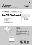
APAX-5202P
2-Port AMONet
RS-485 Master Module
User Manual
Copyright
The documentation and the software included with this product are copyrighted 2010 by Advantech Co., Ltd. All rights are reserved. Advantech
Co., Ltd. reserves the right to make improvements in the products
described in this manual at any time without notice. No part of this manual may be reproduced, copied, translated or transmitted in any form or
by any means without the prior written permission of Advantech Co., Ltd.
Information provided in this manual is intended to be accurate and reliable. However, Advantech Co., Ltd. assumes no responsibility for its use,
nor for any infringements of the rights of third parties, which may result
from its use.
Acknowledgements
AMONet and APAX-5202P are trademarks of Advantech Inc.
Intel and Pentium are trademarks of Intel Corporation.
Microsoft Windows and MS-DOS are registered trademarks of
Microsoft Corp.
All other product names or trademarks are properties of their respective
owners.
Part No. 2003120210
1st Edition
Printed in Taiwan
December 2010
APAX-5202P User Manual
ii
Product Warranty (2 years)
Advantech warrants to you, the original purchaser, that each of its products will be free from defects in materials and workmanship for two years
from the date of purchase.
This warranty does not apply to any products which have been repaired or
altered by persons other than repair personnel authorized by Advantech,
or which have been subject to misuse, abuse, accident or improper installation. Advantech assumes no liability under the terms of this warranty as
a consequence of such events.
Because of Advantech’s high quality-control standards and rigorous testing, most of our customers never need to use our repair service. If an
Advantech product is defective, it will be repaired or replaced at no
charge during the warranty period. For out-of-warranty repairs, you will
be billed according to the cost of replacement materials, service time and
freight. Please consult your dealer for more details.
If you think you have a defective product, follow these steps:
1.
Collect all the information about the problem encountered. (For
example, CPU speed, Advantech products used, other hardware
and software used, etc.) Note anything abnormal and list any
onscreen messages you get when the problem occurs.
2.
Call your dealer and describe the problem. Please have your manual, product, and any helpful information readily available.
3.
If your product is diagnosed as defective, obtain an RMA (return
merchandize authorization) number from your dealer. This allows
us to process your return more quickly.
4.
Carefully pack the defective product, a fully-completed Repair and
Replacement Order Card and a photocopy proof of purchase date
(such as your sales receipt) in a shippable container. A product
returned without proof of the purchase date is not eligible for warranty service.
5.
Write the RMA number visibly on the outside of the package and
ship it prepaid to your dealer.
iii
CE
This product has passed the CE test for environmental specifications
when shielded cables are used for external wiring. We recommend the use
of shielded cables. This kind of cable is available from Advantech. Please
contact your local supplier for ordering information.
Technical Support and Assistance
Step 1. Visit the Advantech web site at www.advantech.com/support
where you can find the latest information about the product.
Step 2. Contact your distributor, sales representative, or Advantech's customer service center for technical support if you need additional
assistance. Please have the following information ready before
you call:
- Product name and serial number
- Description of your peripheral attachments
- Description of your software (operating system, version, application software, etc.)
- A complete description of the problem
- The exact wording of any error messages
Packing List
Before setting up the system, check that the items listed below are
included and in good condition. If any item does not accord with the
table, please contact your dealer immediately.
In addition to this User Manual, the package should also include the following items:
1.
APAX-5202P: 2-Port AMONet RS-485 Master Card
2.
Quick Start User Manual
APAX-5202P User Manual
iv
Contents
Chapter
1 Introduction ..................................................... 2
1.1
Card Description ............................................................... 2
1.2
1.3
1.4
Features ............................................................................. 3
Specifications .................................................................... 3
Supported Software ........................................................... 4
1.5
Chapter
Figure 1.1:Functional Block Diagram of APAX-5202P 2
Figure 1.2:APAX-5202P Applications .......................... 3
1.4.1
1.4.2
Programming Library .................................................... 4
Advantech AMONet Device Manager .......................... 4
Application Development ................................................. 4
Figure 1.3:Application Development ............................ 4
2 Installation ....................................................... 6
2.1
2.2
Unpacking ......................................................................... 6
Case Design....................................................................... 7
2.3
Hardware Installation ........................................................ 8
2.4
2.5
2.6
Figure 2.1:APAX-5202P Case Design .......................... 7
2.3.1
2.3.2
2.3.3
2.3.4
Hardware Configuration ................................................ 8
PCI-Slot Socket Selection .............................................. 8
Installation Procedure .................................................... 8
Troubleshooting ............................................................. 8
Driver Installation ............................................................. 9
Connector Descriptions ..................................................... 9
2.5.1
AMONet Extension (CN1 & CN2) ............................... 9
Figure 2.2:AMONet Extension ...................................... 9
Figure 2.3:RS-485 Extension Port ................................. 9
Figure 2.4:AMONet Slave Module Address Setting ... 10
Board ID Switch (SW4) .................................................. 10
Appendix A Motion Signal Connections........................... 12
A.1
Digital Input .................................................................... 12
A.2
Digital Output.................................................................. 16
Table A.1:STA Pins ..................................................... 12
Table A.2:STP Pins ...................................................... 13
Table A.3:PEL and MEL Pins ..................................... 13
Table A.4:ORG Pins .................................................... 14
Table A.5:SLD Pins ..................................................... 14
Table A.6:ALM Pins .................................................... 14
Table A.7:INP Pins ...................................................... 15
Table A.8:RDY Pins .................................................... 15
Table A.9:DI Pins ........................................................ 15
Table A.10:LTC Pins ................................................... 15
Table A.11:EMG Pins .................................................. 16
Figure A.1:Relay Type Output .................................... 16
Table A.12:SVON Pins ................................................ 16
Table A.13:ERC Pins ................................................... 17
v
A.3
Table A.14:RALM Pins ............................................... 17
Table A.15:CMP Pins .................................................. 17
Table A.16:OUT1&OUT2 Pins ................................... 17
Table A.17:BSY Pins ................................................... 18
DDA Pulse Output .......................................................... 18
APAX-5202P User Manual
Figure A.2:Differential Mode ...................................... 18
Figure A.3:Single Ended Mode ................................... 18
Table A.18:DDA Pulse Pins ........................................ 19
Table A.19:Encoder Pins ............................................. 20
vi
CHAPTER
1
2
Introduction
This chapter gives an overview of the
product features, applications, and
specifications for APAX-5202P
Sections include:
• Card Description
• Features
• Specifications
• Supported Software
• Application Development
Chapter 1 Introduction
APAX-5202P is a standard PCI-Bus motion controller with a high-speed
real-time network extension called AMONet. Advantech optimizes the
software to help you get your advanced motion profiles as quickly as possible. APAX-5202P is equipped with 2 master rings, and each master ring
can connect with up to 64 slave modules. There are 2 categories of slave
modules; one is for 4-axis motion control; the second is for digital I/O
with 3 types, 32-IN, 32-OUT, 16-IN & 16-0UT.
1.1 Card Description
APAX-5202P is a Standard AMONet PCI-Bus Interface Master Card.
Figure 1.1: Functional Block Diagram of APAX-5202P
APAX-5202P User Manual
2
Figure 1.2: APAX-5202P Applications
1.2 Features
• 2 Rings of AMONet master
• Programmable baud-rate up to 20 Mbps transfer rate
• Max. 128 AMONet digital slave modules support
• Easy installation with RJ45 phone jack and LED diagnostic
1.3 Specifications
• Number of Rings: 2
• Transmission Speeds: 2.5, 5, 10, 20 Mbps with automatic flow control
• Serial Interface: Half duplex RS-485 with transformer isolation
• Cable Type: CAT5 UTP/STP Ethernet cable
• Surge Protection: 10 kV
• Communication Distance: Max. 100 m (20 Mbps/32 slave modules)
• Communication Slave Module Capacity: 2 Rings with Max. 128
• Power Consumption: +5 VDC at 0.5 A typical
• Working Temperature: 0 to 60° C
3
Chapter 1
1.4 Supported Software
1.4.1 Programming Library
For customers who are writing their own programs, we provide
VB/VC++ programming libraries and Windows 2000/XP DLL for
APAX-5202P. These function libraries are shipped with the board. There
is also support for Windows 2000/XP, and Embedded XP.
1.4.2 Advantech AMONet Device Manager
Advantech AMONet Device Manager is a utility software tool for AMONet. It is usually used offline to test and debug the communication status,
I/O slave module operation and motion slave operation.
1.5 Application Development
Figure 1.3: Application Development
Advantech also provides Motion Slave Module such as AMAX-2240
series and AMAX-2750 series. If you want to get more information about
them, please refer to the Advantech website.
APAX-5202P User Manual
4
CHAPTER
2
2
Installation
This chapter describes how to install
APAX-5202P.
Sections include:
• Unpacking
• PCB Board Layout
• Hardware Installation
• Driver Installation
• Connector Descriptions
• BoardID Switch
• Jumper Setting
Chapter 2 Installation
This chapter describes how to install the APAX-5202P. Please follow
these steps below to install the APAX-5202P.
• Unpacking (section 2.1)
• Check PCB Board (section 2.2)
• Install hardware (section 2.3)
• Install software driver (section 2.4)
2.1 Unpacking
In addition to this User Manual, the package should also include the following items:
• APAX-5202P: 2-Port AMONet RS-485 Master Card
If any of these items are missing or damaged, contact the dealer from
whom you purchased the product. Save the shipping materials and carton
in case you want to ship or store the product in the future.
APAX-5202P User Manual
6
2.2 Case Design
Figure 2.1: APAX-5202P Case Design
Name
Description
APAX-5202P
Ring 0
RJ-45, AMONet extension connector
Ring 1
RJ-45, AMONet extension connector
PWR
Power Indicator
COM
Communication Status Indicator
ERR
Communication Error Indicator
7
Chapter 2
2.3 Hardware Installation
2.3.1 Hardware Configuration
APAX-5202P is a standard extension device of PCI for PC systems. All
the functions in a base system, such as the memory allocation, I/O port
locations, and address assignments, should be setup by following the
manual.
2.3.2 PCI-Slot Socket Selection
APAX-5202P supports standard PCI bus, and it only can be plugged on
an APAX controller.
2.3.3 Installation Procedure
1.
Please read this manual first, and then setup the jumper and switch
of the product in accordance to your needs.
2.
Turn off your APAX controller power, and make sure the power is
disconnected. Also turn off all accessories.
3.
Before handling APAX-5202P, discharge any static buildup on
your body which may damage the product.
4.
Position APAX-5202P in the correct APAX PCI Slot, and fix it.
5.
When removing the product, be sure to cut off the power first. Then
take APAX-5202P out of the system board.
2.3.4 Troubleshooting
If your system doesn’t boot correctly, please turn it off and make sure the
AC power is disconnected. Open the chassis cover of the PC and confirm
that APAX-5202P is firmly attached in its socket, that screws are locked
and APAX-5202P is set with correct jumper and switch configuration.
Please make sure the PC system is working correctly when APAX-5202P
is removed. If the PC system is working correctly after removing APAX5202P, please follow standard installation steps to reinstall APAX5202P. If the system still can’t boot correctly after the reinstallation of
APAX-5202P, please contact your supplier for support.
APAX-5202P User Manual
8
2.4 Driver Installation
Auto-Run from the Advantech Driver CD. Choose Driver Installation ->
APAX-5202P. Follow the procedures of the installer. After setup installation is completed, restart Windows.
2.5 Connector Descriptions
2.5.1 AMONet Extension (CN1 & CN2)
Figure 2.2: AMONet Extension
Pin
Label
Description
1
2
3
4
5
6
7
8
FG
FG
RS485+
FG
FG
RS485FG
FG
Filed Ground
Filed Ground
High Speed RS-485 protocol
Filed Ground
Filed Ground
High Speed RS-485 protocol
Filed Ground
Filed Ground
Figure 2.3: RS-485 Extension Port
9
Chapter 2
Figure 2.4: AMONet Slave Module Address Setting
2.6 Board ID Switch (SW4)
Pin
Label
ON
OFF
1
ID0
0
1
2
ID1
0
1
3
ID2
0
1
4
ID3
0
1
Note: Node Number=8xID3+4xID2+2xID1+ID0
Default Setting: All the switches are in ON status
APAX-5202P User Manual
10
APPENDIX
A
2
Motion Signal
Connections
Appendix A Motion Signal Connections
This section is extracted from Advantech Motion Slave Module AMAX2210 series. Please refer to the related Manual in the CD to get more
information about the hardware setting of AMAX-2210 series.
CDROM\Manual\AMAX-2210 Series.pdf
A.1 Digital Input
This section includes STA, STP, PCS, CLR, EL+, EL-, ORG, SD, LTC,
EMG, ALM, INP, RDY, IN1 and IN2 signal:
STA (Simultaneous Start)
STA is used to start all the motors connected to the same ring simultaneously, not supported by the current dynamic link library (DLL) driver
now.
Table A.1: STA Pins
Label
Description
STA
Simultaneous Start Signal
EGND
External Ground
APAX-5202P User Manual
12
STP (Simultaneous Stop)
STP is used to stop all the motors connected to the same ring simultaneously, not supported by the current dynamic link library (DLL) driver
now.
Table A.2: STP Pins
Label
Description
STP
Simultaneous Stop Signal
EGND
External Ground
PCS (Position Change)
This function is conserved for the further application, not supported by
the current dynamic link library (DLL) driver now.
CLR (Clear Position Command Counter)
This function is conserved for the further application, not supported by
the current dynamic link library (DLL) driver now.
EL+ & ELThere are two end-limit signals called EL+ & EL-. The default setting is
Normal-Open type signals from external sensors (Can be set by AMAX2210 series SW2). PEL indicates the limit of motion in the plus direction
and MEL indicates the limit of motion in the minus direction. The relative
signal names, pin number are shown in the following table.
Table A.3: PEL and MEL Pins
Label
Description
EGND
External Ground
EL+
Plus End Limit
EL-
Minus End Limit
13
Appendix A
ORG (Origin)
The origin signal is necessary when the position feedback is of the incremental type or if no feedback encoders are used. The origin signals are
used to indicate the origin of the system.
Table A.4: ORG Pins
Label
Description
EGND
External Ground
ORG
ORG signal
SD (Slow Down)
SD signals are used to help the axis decelerate to stop by hardware.
Table A.5: SLD Pins
Label
Description
EGND
External Ground
SLD
SLD Signal
ALM (Servo Alarm)
ALM- input signal from ALM signal at servo driver. The servo driver will
issue ALM output when it is under abnormal operation or overload.
Table A.6: ALM Pins
Label
Description
EGND
External Ground
ALM
Servo ALM input
APAX-5202P User Manual
14
INP (Servo In Position)
INP is an input signal at AMAX-2210 Series and is used to read the INP
status inside servo driver.
Table A.7: INP Pins
Label
Description
EGND
External Ground
INP
Servo In-Position Input
RDY (Driver Ready)
RDY is an input signal and is used to read the RDY signal at servo driver.
Table A.8: RDY Pins
Label
Description
EGND
External Ground
RDY
Servo RDY input
IN1 & IN2 (Digital Input)
Digital input is shown in Table A.9.
Table A.9: DI Pins
Label
Description
DI
General DI
EGND
External Ground
LTC (Counter Latch)
LTC is used to latch the value in the counter when the LTC input is active.
Table A.10: LTC Pins
Label
Description
LTC
LTC- Input
EGND
External Ground
15
Appendix A
EMG (Emergency Stop)
Table A.11: EMG Pins
Label
Description
EMG
Emergency Stop
EGND
External Ground
A.2 Digital Output
This section includes SVON, ERC, RALM, CMP, OUT1 & OUT2 signal:
Figure A.1: Relay Type Output
SVON (Servo On)
SVON is an output signal used to make driver servo-on to hold the motor.
Table A.12: SVON Pins
Label
Description
SVON
SVON Output
EGND
External Ground
ERC (Reset Driver Error Counter/Deviation Counter Clear)
ERC output will be active when the following conditions are activated.
• Homing is complete
• PEL/MEL is active
• ALM is active
• User issues EMG by software
APAX-5202P User Manual
16
For safety reasons, please issue ERC before SVON.
Table A.13: ERC Pins
Label
Description
ERC
Reset Driver error
Counter
EGND
External Ground
RALM (Reset Servo Alarm)
This RALM signal is designed to reset ALM status inside the servo driver
if the alarm status can be reset.
Table A.14: RALM Pins
Label
Description
EGND
External Ground
RALM
ALM reset output
CMP (Position Compare)
CMP signals are used to make a comparison between target value and
actual value and generate a trigger signal output.
Table A.15: CMP Pins
Label
Description
CMP
CMP Output
EGND
External Ground
OUT1 & OUT2 (Digital Output)
Digital output is designed for general-purpose output function.
Table A.16: OUT1&OUT2 Pins
Label
Description
DO
Digital Outputs
EGND
External Ground
17
Appendix A
BSY (Motion Busy Signal Output)
BSY signals indicate the current status of the motors.
Table A.17: BSY Pins
Label
Description
BSY
Motion busy signal output
EGND
External Ground
A.3 DDA Pulse Output
OUT and DIR (Pulse Output Control)
There are eight types of pulse output for AMAX-2210 Series. Specify the
electrical specification as differential or open collector. Then select DIR/
OUT or CW/CCW. Please refer to the AMAX-2210 Series Manual for
the pin definition of the DIR/OUT pins.
Figure A.2: Differential Mode
Figure A.3: Single Ended Mode
APAX-5202P User Manual
18
Table A.18: DDA Pulse Pins
Label
Description
OUT+
OUT(+)
OUT-
OUT(-)
DIR+
DIR(+)
DIR-
DIR(-)
19
Appendix A
Encoder Feedback Signal
EA, EB, and EZ for differential line driver input.
Table A.19: Encoder Pins
Label
Description
EA+
Encoder A (+)
EA-
Encoder A (-)
EB+
Encoder B (+)
EB-
Encoder B (-)
EZ+
Encoder Z (+)
EZ-
Encoder Z (-)
APAX-5202P User Manual
20