1
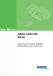
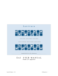
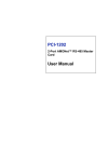
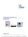
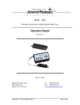
AMAX-2700 Series
16/32-ch AMONet RS-485
Isolated Digital I/O Slave Modules
User Manual
Copyright
The documentation and the software included with this product are copyrighted 2006 by Advantech Co., Ltd. All rights are reserved. Advantech
Co., Ltd. reserves the right to make improvements in the products
described in this manual at any time without notice. No part of this manual may be reproduced, copied, translated or transmitted in any form or
by any means without the prior written permission of Advantech Co., Ltd.
Information provided in this manual is intended to be accurate and reliable. However, Advantech Co., Ltd. assumes no responsibility for its use,
nor for any infringements of the rights of third parties, which may result
from its use.
Acknowledgements
AMONet, AMAX-2730, AMAX-2752, AMAX-2754, and AMAX-2756
are trademarks of Advantech Inc.
Intel and Pentium are trademarks of Intel Corporation.
Microsoft Windows and MS-DOS are registered trademarks of
Microsoft Corp.
All other product names or trademarks are properties of their respective
owners.
Part No. 2003M73000
1st Edition
Printed in Taiwan
November 2006
AMAX-2700 Series User Manual
ii
Product Warranty (2 years)
Advantech warrants to you, the original purchaser, that each of its products will be free from defects in materials and workmanship for two years
from the date of purchase.
This warranty does not apply to any products which have been repaired or
altered by persons other than repair personnel authorized by Advantech,
or which have been subject to misuse, abuse, accident or improper installation. Advantech assumes no liability under the terms of this warranty as
a consequence of such events.
Because of Advantech’s high quality-control standards and rigorous testing, most of our customers never need to use our repair service. If an
Advantech product is defective, it will be repaired or replaced at no
charge during the warranty period. For out-of-warranty repairs, you will
be billed according to the cost of replacement materials, service time and
freight. Please consult your dealer for more details.
If you think you have a defective product, follow these steps:
1.
Collect all the information about the problem encountered. (For
example, CPU speed, Advantech products used, other hardware
and software used, etc.) Note anything abnormal and list any
onscreen messages you get when the problem occurs.
2.
Call your dealer and describe the problem. Please have your manual, product, and any helpful information readily available.
3.
If your product is diagnosed as defective, obtain an RMA (return
merchandize authorization) number from your dealer. This allows
us to process your return more quickly.
4.
Carefully pack the defective product, a fully-completed Repair and
Replacement Order Card and a photocopy proof of purchase date
(such as your sales receipt) in a shippable container. A product
returned without proof of the purchase date is not eligible for warranty service.
5.
Write the RMA number visibly on the outside of the package and
ship it prepaid to your dealer.
iii
CE
This product has passed the CE test for environmental specifications when
shielded cables are used for external wiring. We recommend the use of
shielded cables. This kind of cable is available from Advantech. Please contact your local supplier for ordering information.
Technical Support and Assistance
Step 1. Visit the Advantech web site at www.advantech.com/support
where you can find the latest information about the product.
Step 2. Contact your distributor, sales representative, or Advantech's customer service center for technical support if you need additional
assistance. Please have the following information ready before you
call:
- Product name and serial number
- Description of your peripheral attachments
- Description of your software (operating system, version, application software, etc.)
- A complete description of the problem
- The exact wording of any error messages
Packing List
Before setting up the system, check that the items listed below are included
and in good condition. If any item does not accord with the table, please
contact your dealer immediately.
In addition to this User Manual, the package should also include the following items:
1.
AMAX-2730, AMAX-2752, AMAX-2754, or AMAX-2756:
AMONet Slave Modules
2.
Advantech Driver Disc
AMAX-2700 Series User Manual
iv
Contents
Chapter
1 Introduction ..................................................... 2
1.1
1.2
Chapter
Features ............................................................................. 2
Specifications .................................................................... 3
1.2.1
1.2.2
1.2.3
General ........................................................................... 3
Isolated Digital Input ..................................................... 3
Isolated Digital Output ................................................... 3
2 Hardware Functionality ................................. 6
2.1
Dimensions........................................................................ 6
2.2
Power Connector ............................................................... 7
Figure 2.1:AMAX-2700 Series Dimensions ................. 6
2.2.1
2.2.2
2.3
AMONet Interface............................................................. 8
2.3.1
2.3.2
2.4
2.5
2.6
2.7
2.8
2.9
2.10
Module Power Connector (CN1) ................................... 7
Table 2.1:Module Power Connector Pin Assign (CN1) 7
External Power Connector (CN2) .................................. 7
Table 2.2:External Power Connector Pin Assign(CN2) 7
AMONet Extension (CN3, CN4) ................................... 8
Figure 2.2:RS-485 Extension Port ................................. 8
AMONet Extension Interface ........................................ 8
Figure 2.3:AMONet Slave Module Address Setting ..... 8
Board ID Switch (SW1) .................................................... 9
Configuration Setting (SW2) ............................................ 9
Configuration Setting (SW3) .......................................... 10
LED Definition................................................................ 10
2.7.1
2.7.2
2.7.3
2.7.4
AMAX-2730
AMAX-2752
AMAX-2754
AMAX-2756
................................................................ 10
................................................................ 11
................................................................ 11
................................................................ 12
Pin Definitions................................................................. 13
2.8.1
2.8.2
2.8.3
2.8.4
AMAX-2730
AMAX-2752
AMAX-2754
AMAX-2756
................................................................ 13
................................................................ 14
................................................................ 15
................................................................ 16
Signal Connection ........................................................... 17
Field Wiring Considerations ........................................... 18
v
Table of Contents
AMAX-2700 Series User Manual
vi
CHAPTER
1
2
Introduction
This chapter gives an overview of the
product features, and specifications for
AMAX-2700 Series
Sections include:
• Features
• Specifications
Chapter 1 Introduction
Products in the AMAX-2700 Series are used to increase the number of
digital input/output channels for an AMONet RS-485 distributed motion
control network. These extension slave modules connect serially by a
simple and affordable Cat.5 LAN cable, reducing the wiring between
driver and controller. This is very suitable for highly integrated machine
automation applications.
1.1 Features
• DIN-rail mounting
• Max. 20Mbps transfer rate
• Onboard terminal for direct wiring
• Easy installation with RJ45 phone jack and LED diagnostic
• LED indicator for each IO channel
• Highly integrated and compact size
• 2500 Vrms isolation protection
AMAX-2700 SeriesUser Manual
2
1.2 Specifications
1.2.1 General
BUS TYPE
AMONet RS-485
Certifications
CE
Connectors
RJ45 (AMONet),
Detachable Screw Terminal (I/O)
Power, Run, Error, Isolated Digital I/O
LED Indicators
Power Consumption
Power Supply
Power Supply for
Digital Input/Output
(EXT_VCC)
AMAX-2730: 5W typical, 60W max.
AMAX-2752: 18W typical, 60W max.
AMAX-2754: 2W typical, 60W max.
AMAX-2756: 10W typical, 60W max.
10~30V (CN1)
10-30V (CN2)
1.2.2 Isolated Digital Input
Digital Input
8(AMAX-2730)/ 16(AMAX-2756)/
32(AMAX-2752)
Dry contact (but need EXT_VCC)
Isolation Protection
2500VRMS
Opto-Isolator Response Time
18 us
Input Impedance
2.4K
Channels
1.2.3 Isolated Digital Output
Output type
8(AMAX-2730)/ 16(AMAX-2756)/
32(AMAX-2754)
Sink (NPN) (open collector Darlington)
Isolation Protection
2500VRMS
Output Voltage
5-30V
Sink Current
Max. 500mA per channel, 1.1A total
Channels
3
Chapter 1
AMAX-2700 SeriesUser Manual
4
CHAPTER
2
2
Hardware Functionality
This chapter shows the hardware functionality of AMAX-2700 Series
Sections include:
• PCB Board Layout
• Power Connector
• AMONet Interface
• BoardID Switch
• Configuration Setting
• LED Definition
• Pin Definition
• Signal Connection
• Field Wiring Considerations
Chapter 2 Hardware Functionality
2.1 Dimensions
Figure 2.1: AMAX-2700 Series Dimensions
Name
Description
CN1
CN2
CN3
CN4
CN5
CN6
SW1
SW2
SW3
Module Power
External Power
AMONet Connector
AMONet Connector
Digital I/O Connector
Digital I/O Connector
BoardID Switch
Configuration Setting
Configuration Setting
AMAX-2700 Series User Manual
6
2.2 Power Connector
2.2.1 Module Power Connector (CN1)
Table 2.1: Module Power Connector Pin Assign (CN1)
Pin
Signal Name
1
+VS (10~30V)
2
GND
3
Field Ground
2.2.2 External Power Connector (CN2)
Table 2.2: External Power Connector Pin Assign(CN2)
Pin
Signal Name
1
+EVS (10~30V)
2
EGND
7
Chapter 2
2.3 AMONet Interface
2.3.1 AMONet Extension (CN3, CN4)
Pin
Label
Description
1
2
3
4
5
6
7
8
FG
FG
RS485+
FG
FG
RS485FG
FG
Field Ground
Field Ground
High Speed RS-485 protocol
Field Ground
Field Ground
High Speed RS-485 protocol
Field Ground
Field Ground
Figure 2.2: RS-485 Extension Port
2.3.2 AMONet Extension Interface
Figure 2.3: AMONet Slave Module Address Setting
AMAX-2700 Series User Manual
8
2.4 Board ID Switch (SW1)
Pin
1
2
3
4
5
6
Label
DN5
DN4
DN3
DN2
DN1
DN0
ON
1
1
1
1
1
1
OFF
0
0
0
0
0
0
Note: Node Number=32xDN5+16xDN4+8xDN3+4xDN2+2xDN1+DN0
Default Setting: All the switches are in OFF status
2.5 Configuration Setting (SW2)
Switch Label Description
1
SPD1 Baud-Rate Setting
2
SPD0
3
TUD
Time-Out Status Latch
4
TM
Specify watchdog timer time
5
BRK
*Break & Rescan Communication
Note: BRK is reserved
How to Use the Baud-Rate Setting
SPD0
SPD1 Baud-Rate Setting
OFF
OFF
1/4 System Clock
OFF
ON
1/8 System Clock
ON
OFF
1/16 System Clock
ON
ON
1/32 System Clock
ON
0
0
Disable
N.C.
Disable
OFF
1
1
Enable
N.O.
Enable
Note: default system clock = 80 MHz
Default Setting: All the switches are in OFF status
TUD:
When TUD = HIGH --- The LSI keeps its current status.When the TUD = LOW --- Reset I/O port output,
and immediately stops pulse output (stop operation).
9
Chapter 2
TM
TM
ON
OFF
20M
20ms
5ms
10M
40ms
10ms
5M
80ms
20ms
2.5M
160ms
40ms
2.6 Configuration Setting (SW3)
Switch
Label
ON
OFF
1
2
3
4
Pulse Type
No Use
No Use
Terminal Resistor
Single
Differential
With TR
Without TR
Default Setting: All the switches are in OFF status
2.7 LED Definition
2.7.1 AMAX-2730
LED
Description
PWR
RUN
ERR
DI<0~7>
DO<0~7>
Power
Communication
Communication Error
Isolated Digital Input
Isolated Digital Output
AMAX-2700 Series User Manual
10
2.7.2 AMAX-2752
LED
Description
PWR
RUN
ERR
5/6
DI<0~31>
Power
Communication
Communication Error
LED Working for CN5/CN6*
Isolated Digital Input
* OFF:CN6 ON:CN5
2.7.3 AMAX-2754
LED
Description
PWR
RUN
ERR
5/6
DO<0~7>
Power
Communication
Communication Error
LED Working for CN5/CN6*
Isolated Digital Output
11
Chapter 2
2.7.4 AMAX-2756
LED
Description
PWR
RUN
ERR
5/6
DO<0~31>
Power
Communication
Communication Error
LED Working for CN5/CN6*
Isolated Digital Output
AMAX-2700 Series User Manual
12
2.8 Pin Definitions
2.8.1 AMAX-2730
13
Chapter 2
2.8.2 AMAX-2752
AMAX-2700 Series User Manual
14
2.8.3 AMAX-2754
15
Chapter 2
2.8.4 AMAX-2756
Pin
DI<0~31>
DO<0~31>
DO_COM0
DO_COM1
DO_COM2
DO_COM3
+EVS
GND
Reference Direction Description
GND
Input
Isolated digital input channels
DO_CO
Output
Isolated digital output chanM
nels
Input
Common pin for inductive
loads of DO0~7
Input
Common pin for inductive
loads of DO8~15
Input
Common pin for inductive
loads of DO16~23
Input
Common pin for inductive
loads of DO24~31
GND
Output
External voltage supply*
Isolated ground
*NOTE: The total output current of the “+EVS” pins on each connector
(CN5/CN6) is limited to 1000mA (Output voltage: 10~30V, based on the
external power supply)
AMAX-2700 Series User Manual
16
2.9 Signal Connection
Isolated Digital Output
Each of isolated output channels comes equipped with a Darlington transistor. Every 8 output channels share common collectors and integral suppression diodes for inductive loads.
Note: If an external voltage (5 ~ 30 VDC) is applied to an isolated output
channel while it is being used as an output channel, the current will flow
from the external voltage source to the card. Please take care that the current through each IDO pin not exceed 500 mA.
The figure below shows how to connect an external output load to the
modules’ isolated output channels.
Isolated Digital Input
Figure 3-3 shows how to connect an external input source to one of the
module’s isolated input channels
17
Chapter 2
2.10 Field Wiring Considerations
When you use AMAX-2700 SERIES to acquire data from outside, noises
in the environment might significantly affect the accuracy of your measurements if due cautions are not taken. The following measures will be
helpful to reduce possible interference running signal wires between signal sources and the AMAX-2700 SERIES.
The signal cables must be kept away from strong electromagnetic sources
such as power lines, large electric motors, circuit breakers or welding
machines, since they may cause strong electromagnetic interference.
Keep the analog signal cables away from any video monitor, since it can
significantly affect a data acquisition system.
If the cable travels through an area with significant electromagnetic interference, you should adopt individually shielded, twisted-pair wires as the
analog input cable. This type of cable has its signal wires twisted together
and shielded with a metal mesh. The metal mesh should only be connected to one point at the signal source ground.
Avoid running the signal cables through any conduit that might have
power lines in it.
If you have to place your signal cable parallel to a power line that has a
high voltage or high current running through it, try to keep a safe distance
between them. Or place the signal cable in a right angle to the power line
to minimize the undesirable effect.
AMAX-2700 Series User Manual
18