1
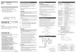
4.6 Varley Loop Test
(1) Connect the looped line under test to Rx termi-
Simplified circuit diagram of Varley loop test is il-
nals. Connect "G" terminal to the earth.
lustrated in Fig. 4.3.
(2) Turn the selector switch to "MV".
(3) Set MULTIPLY dial between M10, M100 and
M1000.
(4) Press the "BA" button switch and "GA" button
switch. Adjust measuring arm dials until the galvanometer indicates "0".
(5) Obtain the value refering to the following equation:
R x1=2L.
(MULTIPLY factor)
(MULTIPLY factor)+(Total value
of MEASURING DIALS) ohms
Rx1:
Resistance between 1 terminal
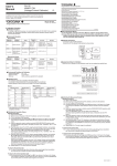
Table 4.3 Varley Loop Test
and the fault point.
2L:
Total resistance of looped line
(1) Connect the looped line under test to Rx termi-
under test.
nals. Connect the "G" terminal to the earth.
(2) Turn the selector switch to "MV".
(3) Set the MULTIPLY dial to proper range of 0.001
to 1000.
IM 2755-97E
– 9 –