1
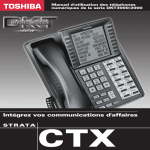
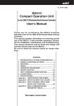
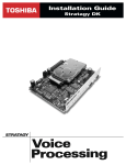
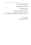
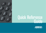
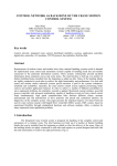
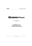
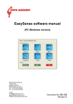
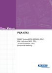
Strata® DK
Application Bulletin
ABDK-0003
August 21, 1998
4170125
Networking the Strata DK424 with
the ADTRAN ATLAS 800™ and TSU120™
Toshiba is currently developing integration of a networking protocol to support the interconnection
of Strata DK products in a private networking environment. The protocol is QSIG, an international
standard for PBX internetworking, which provides a very sophisticated networking scheme for
private networks while providing gateway access to public networks.
With the use of QSIG, Toshiba will be able to provide basic calling services for name and number
delivery over the network, centralized voice mail, flexible numbering plans, network routing and
call control, incoming/outgoing gateway functions, and other feature transparency.
However, prior to the introduction of QSIG in Strata DK, there will be times when a basic
networking requirement will exist. In support of these opportunities, Toshiba has identified three
applications where a limited amount of networking can be applied using an adjunct product
available through ADTRAN. These three applications support:
♦
Centralized voice mail
♦
Coordinated numbering plan
♦
Off-net toll bypass over a private network
These applications represent those found in campus environments, such as school districts, where
the Strata DK can take advantage of the ADTRAN ATLAS 800 and TSU120 systems to provide a
basic level of networking.
Toshiba will not be a reseller of the ADTRAN product. However, we have installed and tested
these applications internally at Toshiba and will be available to assist a dealer with inquiries
concerning the installation of Toshiba Strata DK and Stratagy voice mail systems with the
ADTRAN ATLAS 800 and TSU120 products. Integration assistance with non-Toshiba hardware
will not be supported.
ADTRAN requires certification for dealers wishing to resell the ATLAS 800. If you are not
presently certified to resell the ATLAS 800, please call ADTRAN at 1-800-9ADTRAN for
assistance with contacting a local ADTRAN territory manager.
ADTRAN Product
ATLAS, the ADTRAN Total Access System, is a modular, scalable platform that provides
solutions for wide area communications needs of medium to large clients. ATLAS is an integrated
access switch that provides extensive support of dedicated bandwidth and access management.
Toshiba America Information Systems, Inc.
Telecommunication Systems Division
9740 Irvine Blvd., Irvine, CA 92618-1697 (949) 583-3700
http://telecom.toshiba.com
1 of 6
Application Overview: Centralized Voice Mail
ABDK-0003
The ATLAS 800, with the appropriate modules installed can function as a:
♦
Digital access and cross connect (DACS)
♦
T1 bandwidth manager
♦
ISDN access switch
tia
l
The ATLAS can be configured to switch calls to specific ports or DSOs based on the number that
is dialed. Switched connection mapping is supported for dialed calls placed over BRI, PRI, or
channelized T1. Multiple T1 (N x T1, where N = 1~24) and Fractional T1 (FT1) are supported.
nf
id
en
The ADTRAN TSU120 T1 service unit is an intelligent T1/FT1 DSU/CSU. It is designed to
interface with CPE T1 and FT1 services. The TSU120 supports a single DSX-1 and V.35 port
standard on the unit. The V.35 port is capable of handling N x 56/64 Kbps data rates, where N =
1~24.
Expansion modules are available for the TSU120 that can provide additional ports for specific
application needs. These include N x 56/64Kbps Office Channel Unit Data Pool (OCU DP), dial
back up, FXO/FXS, E&M, drop and insert, SNMP agent, and V.34 modem.
Co
The three applications mentioned previously are discussed in this application note. For the
purposes of these applications, T1 or FT1 are used. Due to the complexity and programming
variations available on the ADTRAN ATLAS 800 product, specific programming for this product
is left to the installing party. Please refer to the appropriate ADTRAN programming instructions
for this information.
d
Application Overview: Centralized Voice Mail
1XXX
R
D
T
U
ar
R
S
T
U
2XXX
Strata DK424
y
Strata DK424
an
This bulletin covers the requirements to support a centralized voice mail application using the
Strata DK, Stratagy® Voice Mail Processing System and ADTRAN TSU120 (see Figure 1).
N x T1
ADTRAN
ATLAS 800
(see Important Note)
T1/FT1
TSU120
in
FXO
R
D
T
U
el
im
3XXX
Pr
Stratagy
Voice Processing
Figure 1
T1/FT1
Strata DK424
TSU120
FXO
R
D
T
U
R
S
T
U
3637
Centralized Voice Mail Example
Important!
2 of 6
R
S
T
U
The ATLAS 800 is not necessary as shown in this application unless Coordinated
Dialing and/or off-net calling is also required. In a point to point configuration, a single
TSU120 would be used without the ATLAS 800.
Networking the Strata DK424 with the ADTRAN ATLAS 800™ and TSU120™
Application Overview: Centralized Voice Mail
ABDK-0003
tia
l
The TSU120 provides clients with the ability to use one integrated voice mail system to service
multiple Strata DK systems over T1 E&M circuits. The integration of the various Strata DK
systems will include inband DTMF for message retrieval, call forwarding to the user’s mailbox,
and activation/deactivation of the station’s message waiting lamps. When using the Stratagy voice
mail system, this application will send different message waiting codes and different transfer codes
on a per mailbox basis.
Hardware Required
nf
id
en
The TSU120 is installed at each remote location requiring access to the centralized voice mail
system. The TSU120 requires an FXO+ Dual Voice card, which is connected to an RSTU port on
the remote Strata DK. At the central site, where the voice mail system is installed, a CSU is
required for access to the telco provided T1 or FT1. A CSU is not required at the remote location,
as the TSU120 is the T1 or FT1 CSU. Additionally, each Strata DK system requires an RDTU card
for the T1 termination on the Strata DK.
Programming the TSU120
To set up the TSU120 for operation in this application, the following parameters must be set:
Config –
Format = ESF
Code = B8ZS
Timing = NI
Bitstuffing = Enable
Config –
DSO Map A
Co
Network
Config –
Port Config
an
d
Edit Temp
Channels 01-22 Port 0.2 DSX-1
Channels 23-24 FXO+
Apply Temp >A
Disrupt Data = YES
ar
y
0.2 DSX-1
Format = ESF
Code = B8ZS
Robbed-bit signal = ON
in
Programming the Strata DK (TSU120 Location)
1. Program 03 – Slot XX=73.
el
im
2. Program *41-11 – LEDs 1 and 2=ON.
3. Program *41-21 – 01*24, CO KIND=4.
4. Program *42-1 – Primary=1.
5. Program single line ports as voice mail ports (Program 31) and connect to the FXO ports.
Pr
6. Program single line ports to a Distributed Hunt Group (DHG) (Program *40).
7. Apply 15-0 and 15-5 to the appropriate lines.
Programming the Strata DK (Voice Mail System Location)
1. Program 03 – Slot XX=73.
2. Program *41-11 – LEDs 1 and 2=ON.
3. Program *41-21 – 01*22 – CO KIND=4; 23*24 – CO KIND=1.
Networking the Strata DK424 with the ADTRAN ATLAS 800™ and TSU120™
3 of 6
Application Overview: Coordinated Dialing Plan
ABDK-0003
4. Program *42-1 – Primary=blank.
5. Program 81-89 – Set T1 circuits 23*24 ring to voice mail pilot/DHG.
6. Program T1 circuits 23*24 in a Program 16 group (801).
7. Program T1 circuits 01*22 in a Program 16 group (802).
tia
l
8. Apply 15-0 and 15-5 to the appropriate lines.
Programming the Remote Site Strata DK Station Ports (TSU120 Location)
nf
id
en
1. Program the station’s call forward string to the DHG connected to the FXO card through the
single line ports (RSTU card).
2. Program the station’s #656 and #657 for voice mail inband codes.
Programming the Central Site Strata DK with Stratagy Voice Mail
1. In the voice mail, set up each mailbox message waiting string (e.g., 801, #63XXX).
2. In the voice mail, set up each mailbox extension field with the transfer string (e.g., F, 802,
XXX, F, F: Hangup).
●
●
On all DK systems you may want to turn LEDs 4 and 11 ON in Program 10-2 for message
waiting and DTMF.
Programming values are examples and vary per system.
See the ADTRAN User Manual and Strata DK I&M Manual for additional hardware
requirements.
an
d
●
Co
Notes
Application Overview: Coordinated Dialing Plan
ar
y
For support of a coordinated dialing plan, the ADTRAN ATLAS 800 is used in conjunction with
the Strata DK systems. The ATLAS 800 provides the capability of dialing 2-4 digit extension
numbers to multiple Strata DK locations. The numbering plan is programmed within the specific
Strata DK424 systems (see Figure 2).
2XXX
Strata DK424
Strata DK424
R
D
T
U
N x T1
ADTRAN
ATLAS 800
T1/FT1
R
D
T
U
3XXX
PSTN
Pr
el
im
in
1XXX
T1/FT1
Strata DK424
R
D
T
U
3638
Figure 2
4 of 6
Coordinated Dialing Plan
Networking the Strata DK424 with the ADTRAN ATLAS 800™ and TSU120™
Application Overview: Off-net Calling (Toll Bypass)
ABDK-0003
Hardware Required
The Strata DK424 must be equipped with a RDTU T1 card at each location. The interface between
the Strata DK and the ADTRAN ATLAS 800 will be T1. The ATLAS 800 User Manual provides
details on the appropriate modules and programming required for this application.
tia
l
Programming the Strata DK424
All locations assume the ATLAS 800 is providing the clock source.
1. Program 03 – Slot XX=73.
nf
id
en
2. Program *41-1X – LEDs 1 and 2=ON.
3. Program *41-2X – 01*24, CO KIND=4.
4. Program *42-1 – Primary=1.
5. Program 16 – Place T1 circuits into a separate CO line group.
6. Program 39 – Port XXX=key XX=3XX (3XX represents the appropriate pooled key from CO
line group in Program 16 from Step #5).
Programming the ATLAS 800
Co
➤ Please refer to the ATLAS 800 User Manual for detailed programming procedures.
Operation (Calling Other Sites)
an
d
1. Station will access pooled line key or dial the appropriate CO line group number.
2. Station will dial appropriate network station number.
Application Overview: Off-net Calling (Toll Bypass)
y
The ATLAS 800 can provide the capability of dialing an external telephone number and routing it
out over the appropriate remote Strata DK site. This can be accomplished with Pooled Line
buttons or with Least Cost Routing (LCR) (see Figure 3).
2XXX
Strata DK424
Strata DK424
el
im
in
ar
1XXX
Mapping/Routing
Tables
R
D
T
U
N x T1
ADTRAN
ATLAS 800
T1/FT1
R
D
T
U
949-853-1212
949-853-1212
3XXX
T1/FT1
Pr
949-583-3700
Strata DK424
R
D
T
U
3639
949-583-3700
Figure 3
Off-net Calling Example
Networking the Strata DK424 with the ADTRAN ATLAS 800™ and TSU120™
5 of 6
Application Overview: Off-net Calling (Toll Bypass)
ABDK-0003
Hardware Required
Programming the Strata DK424
All locations assume the ATLAS 800 is providing the clock source.
1. Program 03 – Slot XX=73.
nf
id
en
2. Program *41-1X – LEDs 1 and 2=ON.
tia
l
The Strata DK424 must be equipped with a RDTU T1 card at each location. The ADTRAN
ATLAS 800 interface to the Strata DK will be T1. The ATLAS 800 User Manual provides detailed
information on the appropriate programming required for this application.
3. Program *41-2X – 01*24,CO KIND=4.
4. Program *42-1 – Primary=1.
5. Program 16 – Place T1 circuits into a separate CO line group.
6. Program 39 – Port XXX=key XX=3XX (3XX represents the appropriate Pooled Line button
from CO line group in Program 16 from Step #5.
7. Program 50-56 – Program LCR based on T1 circuits entered in Program 16.
Co
Programming the ATLAS 800
➤ Please refer to the ATLAS 800 User Manual for detailed programming procedures.
Operation (Calling other sites)
d
1. Station accesses pooled line key or access LCR.
an
2. Station dials an external number and the system routes over the appropriate T1 per the Strata
DK424 to the ATLAS 800.
Pr
el
im
in
ar
y
3. The ATLAS 800 routes over the appropriate off-net T1.
6 of 6
Networking the Strata DK424 with the ADTRAN ATLAS 800™ and TSU120™