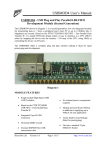
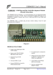
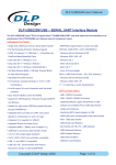
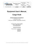
1
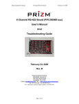
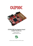
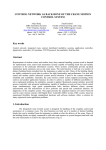
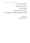
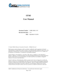
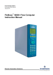
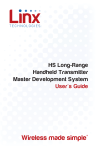
INTERFACE MODULE QS SERIES WIRELESS MADE SIMPLE SDM-USB-QS-S USB MODULE DESIGN GUIDE DESCRIPTION The Linx QS Series USB module allows the rapid 0.812" addition of USB to virtually any device. Housed in a compact SMD package the QS module provides a complete solution for converting between USB and logic level serial sources. The 0.630" USB MODULE SDM-USB-QS1-S module can be directly connected to virtually any LOT 10000 serial device including microprocessors, RS232/RS485 level converters, or Linx wireless TOP VIEW RF modules. The QS module is completely self contained and requires no external components, 0.125" (except a USB jack) and includes all necessary SIDE VIEW firmware and drivers, freeing the designer from complicated programming. Power can be supplied externally or from the USB bus. Both Figure 1: Package Dimensions USB 1.1 and USB 2.0 are supported at data rates to 3Mbps. FEATURES Single Chip USB-to-Asynchronous Serial Data Conversion Low-Cost 3Mbps baud rate Supports Low-Speed USB Full Handshaking Support for RS232 and RS485 Bus-or-Self Powered VID, PID, Serial Number, and Descriptors Programmed via USB No External Components Needed (Except a USB Jack) Compact Surface-mount Package Drivers and Firmware Included Supports Windows 98/2000/ME/XP USB 1.1 and 2.0 Compatible APPLICATIONS INCLUDE Interface / Upgrade Legacy Peripherals Interfacing Microcontrollers To USB USB-to-RS232 / RS485 Converters Interfacing RF Modules To USB USB Smart Card Readers ORDERING INFORMATION USB Modems PART # DESCRIPTION Robotics SDM-USB-QS-S USB Module USB Instrumentation MDEV-USB-QS Master Development Kit USB Game Controllers USB-to-Serial Converter Cables Revised 1/10/04 Page 1 ABSOLUTE MAXIMUM RATINGS Supply voltage VCC Max Current Sourced By Data Pins Max Current Sunk By Data Pins Operating temperature Storage temperature Soldering temperature Any input or output Pin PIN DESCRIPTIONS -0.5 to +6.0 2 4 0 to +70 -40 to +90 +225°C for 10 seconds -0.5 to VCC + 0.5 VDC mA mA °C °C Pin # Name Description 1 USBDP USB data signal plus. 2 USBDM USB data signal minus. 3 GND Ground supply. 4 VCC Positive power supply. 5 SUSP_IND Goes low during USB Suspend Mode. This pin can be used to power down external logic when the host puts the USB bus into suspend mode. 6 RX_IND This line will pulse low when receiving data from the USB bus. This allows for the connection of a LED indicator. 7 TX_IND This line will pulse low when transmitting data on the USB bus. This allows for the connection of a LED indicator. 8 485_TX Transmit enable line for RS485 applications. 9 DTR Data Terminal Ready control / handshake output 10 CTS Clear To Send control / handshake input 11 RTS Request To Send control / handshake output 12 DATA_OUT Transmit asynchronous data output 13 DATA_IN Receive asynchronous data input 14 DSR Data Set Ready control / handshake input 15 DCD Data Carrier Detect control / input 16 RI Ring Indicator control input VDC *NOTE* Exceeding any of the limits of this section may lead to permanent damage to the device. Furthermore, extended operation at these maximum ratings may reduce the life of this device. ELECTRICAL SPECIFICATIONS Parameter POWER SUPPLY Operating Voltage Supply Current UART SECTION Data Rate Data Output Logic Low Logic High EEPROM Size USB SECTION Data Output Logic Low Logic High Single Ended RX Threshold Differential Common Mode Differential Input Sensitivity ENVIRONMENTAL Operating Temperature Range Designation Min. Typical Max. Units Notes VCC ICC 4.4 – 5.0 26 5.26 28 VDC mA – – – 0.3 – 3,000 kbps – VOL VOH 0.1 4.4 – – – – 0.7 4.9 1024 VDC VDC Bits – – – 0 2.8 0.8 0.8 0.2 – – – – – 0.3 3.6 2.0 2.5 – VDC VDC VDC VDC VDC – – – – – +70 °C – UVOL UVOH – – – – 0 – *CAUTION* This product incorporates numerous static-sensitive components. Always wear an ESD wrist strap and observe proper ESD handling procedures when working with this device. Failure to observe this precaution may result in module damage or failure. PIN ASSIGNMENTS 1 USBDP RI 16 2 USBDM DCD 15 3 GND DSR 14 4 VCC DATA_IN 13 5 SUSP_IND DATA_OUT 12 6 RX_IND RTS 11 7 TX_IND CTS 10 8 485_TX DTR 9 Figure 2: SDM-USB-QS-S Pinout (Top View) Page 2 Page 3 PRODUCTION GUIDELINES AUTOMATED ASSEMBLY The QS modules are packaged in a hybrid SMD package that supports hand or automated assembly techniques. Since QS modules contain discrete components internally, the assembly procedures are critical to ensuring the reliable function of the QS product. The following procedures should be reviewed with and practiced by all assembly personnel. PAD LAYOUT The following pad layout diagram is designed to facilitate both hand and automated assembly . 0.065" 0.610" 0.070" 0.100" Figure 3: Recommended PCB Layout HAND ASSEMBLY The QS module’s primary mounting surface is sixteen pads located on the bottom of the module. Since these pads are inaccessible during mounting, castellations that run up the side of the module have been provided to facilitate solder Soldering Iron wicking to the module’s underside. Tip This allows for very quick hand soldering for prototyping and small volume production. If the recommended pad guidelines Solder PCB Pads have been followed, the pads will protrude slightly past the edge of the module. Use a fine soldering tip to Figure 4: QS Soldering Technique heat the board pad and the castellation, then introduce solder to the pad at the module’s edge. The solder will wick underneath the module providing reliable attachment. Tack one module corner first and then work around the device taking care not to exceed the times listed below. Absolute Maximum Solder Times Hand-Solder Temp. TX +225°C for 10 Seconds Hand-Solder Temp. RX +225°C for 10 Seconds Recommended Solder Melting Point +180°C Reflow Oven: +220°C Max. (See adjoining diagram) Page 4 For high-volume assembly most users will want to auto-place the modules. The modules have been designed to maintain compatibility with reflow processing techniques, however, due to the their hybrid nature certain aspects of the assembly process are far more critical than for other component types. Following are brief discussions of the three primary areas where caution must be observed. Reflow Temperature Profile The single most critical stage in the automated assembly process is the reflow process. The reflow profile below should not be exceeded since excessive temperatures or transport times during reflow will irreparably damage the modules. Assembly personnel will need to pay careful attention to the oven's profile to ensure that it meets the requirements necessary to successfully reflow all components while still remaining within the limits mandated by the modules themselves. 300 C Forced Air Reflow Profile Ideal Curve Limit Curve 250 220 C 210 C 200 180 C Temperature 150 Reflow Zone 125 C 20-40 Sec. Soak Zone 100 2 Minutes Max. 50 Ramp-up Preheat Zone 2-2.3 Minutes Cooling 1-1.5 Minutes 0 0 30 60 90 120 150 180 210 240 270 300 330 360 Time (Seconds) Figure 5: Maximum Reflow Profile Shock During Reflow Transport Since some internal module components may reflow along with the components placed on the board being assembled, it is imperative that the modules not be subjected to shock or vibration during the time solder is liquid. Washability The modules are wash resistant, but are not hermetically sealed. Linx recommends wash-free manufacturing, however, the modules can be subjected to a wash cycle provided that a drying time is allowed prior to applying electrical power to the modules. The drying time should be sufficient to allow any moisture that may have migrated into the module to evaporate, thus eliminating the potential for shorting damage during power-up or testing. If the wash contains contaminants, the performance may be adversely affected, even after drying. Page 5 MODULE DESCRIPTION The Linx SDM-USB-QS-S module will convert USB signals from a host, such as a PC or hub, into TTL logic level signals. This enables the module to be connected directly to microcontrollers (or Linx RF modules for wireless applications) or to RS232 or RS485 level converters for communication with legacy devices. The module handles all of the complicated enumeration and bus communication processes thus freeing the designer to focus on handling the data. All necessary firmware is included in the module and the device descriptors can easily be changed to customize the device. The host application software can access the USB device by simple custom functions or by standard Windows Win32 API calls. In addition, Virtual Com Port drivers are available that make the USB module appear to the PC as an additional COM port without the need for additional system resources, such as an IRQ or address. This allows the designer to program the application software to use standard serial or parallel ports and then to simply select the port that represents the USB module. The drivers will then automatically direct the data to the USB bus and the device. THEORY OF OPERATION Figure 7 below shows a block diagram of the QS module. SUSP_IND VCC GND TX Buffer 128 Bytes DATA_OUT DATA_IN RTS CTS USBDP USB Transceiver Serial Interface Engine (SIE) USB Protocol Engine USBDM UART FIFO Controller DTR UART DSR DCD RI 485_TX TX_IND RX_IND USB DPLL RX Buffer 384 Bytes INSTALLING THE DRIVERS The drivers for the USB module are included with the module’s development system or may be downloaded from the Linx web site (www.linxtechnologies.com). These drivers should be downloaded onto the hard drive of a PC or onto a disk. When the module is attached to the PC for the first time Windows will automatically detect the device and search for the best driver. The user will be prompted to provide a location for Windows to find the drivers, so the user will then browse to the folder or the disk, click Next and Windows will do the rest. Windows XP may return an error window shown in the figure below. Clock Figure 7: SDM-USB-QS-S Block Diagram The USB transceiver block provides the physical interface for the USB signalling. The USB DPLL locks onto the NRZ data and provides separate recovered clock and data signals to the Serial Interface Engine (SIE). The SIE performs the parallel to serial and serial to parallel conversion, bitstuffing/un-stuffing, and CRC calculations on the USB data. The USB Protocol Engine manages the data from the USB control endpoint, the USB protocol requests from the USB host controller, and the commands for controlling the functional parameters of the UART. Data from the USB data out endpoint is stored in the TX buffer and removed from the buffer to the UART transmit register under control of the UART FIFO controller. Data from the UART receive register is stored in the RX buffer prior to being removed by the SIE on a USB request for data from the device data in endpoint. The UART FIFO controller handles the transfer of data between the RX and TX buffers and the UART transmit and receive registers. Figure 6: Windows XP Driver Error Window This window is simply a warning that the driver has not gone through Microsoft’s certification process and could potentially pose a problem for the system. The drivers provided for the QS module have been independently tested and should not pose any problems unless modified by the user. Click the Continue Anyway button to finish the installation process. Page 6 The UART performs asynchronous 7/8 bit parallel to serial and serial to parallel conversion of the data on the RS232 (RS422 and RS485) interface. Control signals supported by the UART include RTS, CTS, DSR , DTR, DCD and RI. The UART provides a transmitter enable control signal (485_TX) to assist with interfacing to RS485 transceivers. The UART supports RTS/CTS, DSR/DTR and X-On/X-Off handshaking options. Handshaking, where required, is handled in hardware to ensure fast response times. The UART also supports the RS232 BREAK setting and detection conditions. Page 7 TYPICAL APPLICATIONS The USB module can be powered in two ways: from the USB bus or from an external source. If neccisary, a voltage regulator can be used to supply a clean 5V as the external source, or the VCC pin can be connected to the bus power pin of the USB connector. Using the bus to power the module is an advantage because the module then uses power from the host rather than from the peripheral. This is especially helpful if the peripheral is battery powered. Figure 8 shows the schematic for a bus powered device. There are many potential uses for the QS Series modules, but three will be described here. Figure 9 shows the QS and a MAX213 RS232 level converter IC from Maxim. This creates a USB-to-RS232 converter that supports all of the standard handshaking lines. Similarly, RS485 or RS422 level converter chips could be used for designs requiring those standards. VCC 3 4 5 6 7 8 16 0.1uF + 16V USBDM DCD 15 GND DSR 14 16 VCC DATA_IN 13 TX DATA 7 DATA_OUT 12 DTR SUSP_IND RX_IND RTS TX_IND CTS 485_TX DTR RTS 11 CTS 9 DCD DSR RX DATA RI VCC Note: when these drivers are installed on a system with Windows XP an error message may be displayed stating that these drivers are not certified and could potentially crash the system. As long as no other changes are made to the .inf files, this should not be a concern. Page 8 5 26 22 19 25 GSHD GSHD C1V- 17 + C2T1IN T1OUT T2IN T2OUT T3IN T3OUT T4IN T4OUT R1OUT GND R1IN R2OUT R2IN R3OUT R3IN R4OUT R4IN R5OUT R5IN 0.1uF 16V 2 3 1 SDM-USB-QS-S 1 2 GND MAX213 C2+ 4 3 2 1 GND DAT+ DAT 5V 3 4 GND GND SUSP_IND 5 RI USBDM DCD GND DSR VCC DATA_IN RX_IND 7 8 DTR2 RTS TX_IND CTS 485_TX DTR 220 220 27 23 18 14 13 12 11 10 9 RI DCD DSR RX DATA TX DATA RTS CTS DTR 1 DCD2 VCC 4 16 15 RTS2 28 9 DATA_OUT SUSP_IND 6 TX DATA2 USBDP 6 DSR2 CTS2 TX DATA2 DCD2 RTS2 DSR2 RX DATA2 RX DATA2 CTS2 RI2 DTR2 2 7 3 8 4 9 RI2 EN 5 SHDN GND 10 DB9M Figure 9: RS232 To USB Converter The QS Series modules can be used with Linx RF modules to create a wireless link between two PCs. Figure 10 shows a design using the ES Series RF modules. One potential feature not shown in the schematic below is that one of the output lines of the QS module, RTS or DTR, could be connected to the PDN lines of the RF modules enabling the host to turn the RF modules on and off. The QS can be customized to display your product’s name, manufacturer name, and to use different Product Identifiers (PID) and Vendor Identifiers (VID). This allows an end user to see the final product’s name in their Windows Device Manager and when the hardware is first loaded. The PID and VID are set by the USB Implementers Forum and should not be changed unless the final product has gone through the certification process and received its own unique IDs. RXM-XXX-ES 1 1 VCC 2 3 4 5 TXM-XXX-ES PDN ANT LVL ADJ GND LOW V DET GND /CLK SEL DATA /CLK 10 9 8 7 6 VCC 8 GSHD USB Type B Connector GND DAT+ DAT 5V GND 6 Once the module is reprogrammed some modifications to the driver files may be necessary. If a VID and PID other than the default Linx numbers are used these numbers will need to be added to the files. This requires modifying several lines in the .inf files and is described in detail in the programmer user manual. Modifying the name displayed by the Windows Device Manager requires changing only one line, also described in the programmer user manual. 8 24 SUSP_IND CHANGING THE DEVICE DESCRIPTORS The Manufacturer, Description, and Serial Number strings can all be modified using the Linx Programming Software, which is included in the module’s development system. This easy-to-use software will reprogram the module via the USB bus and can be done as a part of the final testing procedure. 20 21 10 Figure 8: USB Bus Powered Schematic The USB specification has strict allowances for using power from the bus. A device is allowed to use 100mA before enumeration, 500mA during normal operation, and 500µA in suspend mode. A descriptor stored in the EEPROM will tell the host how much current the device will pull from the bus so that the host can allocate the appropriate power. The modules come programmed for 100mA, but if the final product will draw more than this then the device descriptors will need to be changed, as described in the next section. 6 0.1uF 6.3V GND VCC 220 1 2 3 4 5 6 7 8 SDM-USB-QS-S USBDP RI USBDM DSR GND VCC SUSP_IND DATA_OUT RX_IND RTS TX_IND CTS 485_TX DTR TX Side 16 15 14 12 11 10 9 DAT+ DAT 5V NC NC NC NC PDN RSSI DATA AUDIO AREF NC 16 15 14 13 12 11 10 9 GND USB Type B Connector GSHD GND RI 13 GSHD 2 USBDP + V+ 4 3 2 5 1 14 15 C1+ 6 GND SDM-USB-QS-S 11 VCC 5 4 3 2 1 GSHD GND GND 12 0.1uF + 6.3V 5 6 5 GSHD GSHD USB Type B Connector GND DAT+ DAT 5V USB Type B Connector + 0.1uF 6 POWER SUPPLY GUIDELINES GND GND VCC 220 GND 1 2 3 4 5 6 7 8 SDM-USB-QS-S USBDP RI USBDM DCD DSR GND VCC DATA_IN SUSP_IND DATA_OUT RX_IND RTS TX_IND CTS 485_TX DTR 16 15 14 13 12 11 10 9 RX Side Figure 10: Wireless Modem Using The Linx ES Series RF Modules Page 9 TYPICAL APPLICATIONS (CONT) ON-LINE RESOURCES Figure 11 below shows the QS module connected to a microprocessor. This is the design used in the QS Master Development Kit and the documentation for the kit describes the connections and software. WIRELESS MADE SIMPLE VCC 220 1 2 3 4 5 6 7 8 9 220 220 RA2/AN2 RA3/AN3 RA4/AN4 MCLR/VPP GND RB0/INT RB1 RB2/RX RB3 18 17 16 15 14 13 12 11 10 RA1/AN1 RA7 RA6 VCC RB7 RB6 RB5/TX RB4 www.linxtechnologies.com 10K VCC SW-PB 200K PIC16F88 GSHD GND DAT+ DAT 5V SDM-USB-QS-S 4 3 2 1 1 2 3 4 5 6 GSHD USB Type B Connector 5 220 VCC 220 6 7 8 USBDP RI USBDM DCD GND DSR VCC DATA_IN SUSP_IND DATA_OUT RX_IND RTS TX_IND CTS 485_TX DTR 16 15 14 13 12 11 VCC 220 10 9 220 • • • • • Latest News Data Guides Application Notes Knowledge Base Software Updates If you have questions regarding any Linx product and have Internet access, make www.linxtechnologies.com your first stop. Our website is organized in an intuitive format to give you the answers you need in record time. Day or night, the Linx website gives you instant access to the latest information regarding the products and services of Linx. It's all here: manual and software updates, application notes, a comprehensive knowledge base, FCC information and much more. Be sure to visit often! Figure 11: Interface With A Microprocessor SOFTWARE CONSIDERATIONS The host application can access the QS module in two ways. First is through Virtual COM Port drivers. These drivers make the QS appear as an extra COM port on the host PC. This allows the application to use standard writes and reads to a serial port and the drivers will redirect data to the USB device. Second are a series of custom functions supported by the direct driver .dlls. These functions are also described in the Programmer’s Guide where examples are given in both Visual Basic and C. The Programmer’s guide can be downloaded from the Linx web site (www.linxtechnologies.com). In addition to the Programmer’s Guide, the QS Master Development Kit (MDEVUSB-QS) includes example software and sample system source code. This source code provides the driver function declarations, examples of how to use the functions in a program, and other code that may be of use. www.antennafactor.com The Antenna Factor division of Linx offers a diverse array of antenna styles, many of which are optimized for use with our RF modules. From innovative embeddable antennas to low-cost whips, domes to yagi's, and even GPS, Antenna Factor likely offers or can design an antenna to meet your requirements. www.connectorcity.com Through its Connector City division, Linx offers a wide selection of high-quality RF connectors, including FCCcompliant types such as RP-SMAs that are an ideal match for our modules and antennas. Connector City focuses on high-volume OEM requirements, which allows standard and custom RF connectors to be offered at a remarkably low cost. Page 10 Page 11 WIRELESS MADE SIMPLE U.S. CORPORATE HEADQUARTERS: LINX TECHNOLOGIES, INC. 575 S.E. ASHLEY PLACE GRANTS PASS, OR 97526 PHONE: (541) 471-6256 FAX: (541) 471-6251 http://www.linxtechnologies.com Disclaimer Linx Technologies is continually striving to improve the quality and function of its products; for this reason, we reserve the right to make changes without notice. The information contained in this Data Sheet is believed to be accurate as of the time of publication. Specifications are based on representative lot samples. Values may vary from lot to lot and are not guaranteed. Linx Technologies makes no guarantee, warranty, or representation regarding the suitability or legality of any product for use in a specific application. None of these devices is intended for use in applications of a critical nature where the safety of life or property is at risk. The user assumes full liability for the use of product in such applications. Under no conditions will Linx Technologies be responsible for losses arising from the use or failure of the device in any application, other than the repair, replacement, or refund limited to the original product purchase price. Some devices described in this publication are patented. Under no circumstances shall any user be conveyed any license or right to the use or ownership of these patents. © 2004 by Linx Technologies, Inc. The stylized Linx logo, Linx, and “Wireless made Simple” are the trademarks of Linx Technologies, Inc. Printed in U.S.A.