1
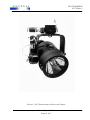
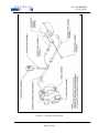
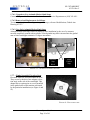
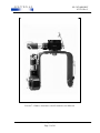
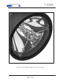
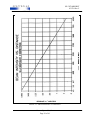
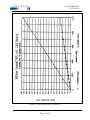
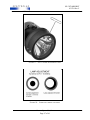
SX-5 STARBURST® SEARCHLIGHT User’s Manual DOC# 031718 REV-C Spectrolab, Inc. 12500 Gladstone Avenue, Sylmar CA 91342-5373 USA Phone: (818) 365-4611; Fax: (818) 365-7680; (818)361-5102 WWW.spectrolab.com SX-5 STARBURST 031718 Rev C CHANGE RECORD REV DATE AUTHORIZATION N/C A B C 12/6/91 8/26/04 3/28/05 6/25/14 KR EQ EQ GPE CHANGE DESCRIPTION INITIAL RELEASE Revised per ECO Revised Per ECO Revised Per ECO Source: Spectrolab, Inc. Page 2 of 61 APPROVAL G.Gonzales F. Sanchez F. Sanchez F. Sanchez SX-5 STARBURST 031718 Rev C SX-5 STARBURST® SEARCHLIGHT USER’S MANUAL Notice to Users • This manual documents the SX-5 Starburst® Searchlight system in the most current configuration as of the date of publication of this document, and may not reflect any later configurations. • Should you have any questions on the equipment you receive, or need any assistance on any aircraft, ground-based or vehicle lights, please contact the Spectrolab Illumination Products Customer Service Department at (818) 365-4611 • Spectrolab searchlights can be used in a variety of applications not mentioned in this manual, and we will be happy to assist in your system design to meet any non-standard applications. • The buyer agrees that protection against consequences resulting from searchlight placement on aircraft is the buyer’s responsibility. • SX-5 Starburst® is a registered trademark of Spectrolab, Inc. Source: Spectrolab, Inc. Page 3 of 61 SX-5 STARBURST 031718 Rev C IMPORTANT SAFETY INFORMATION The SX-5 Starburst® Searchlight is intended for use only by professional, qualified personnel. Attempting installation, use or maintenance of the searchlight system without the appropriate expertise, tools, training and equipment, could cause serious bodily injury and/or damage to the searchlight Source: Spectrolab, Inc. Page 4 of 61 SX-5 STARBURST 031718 Rev C Table Of Contents 1. SYSTEM DESCRIPTION ..........................................................................................................9 1.1. INTRODUCTION AND FEATURES ...................................................................................9 Table 1 - SPECIFICATIONS ...........................................................................................................10 1.2. SYSTEM APPLICATIONS .................................................................................................13 1.2.1. Applications ......................................................................................................................13 1.2.2. Ease of Operation ..............................................................................................................13 1.3. POWER REQUIREMENTS .................................................................................................13 1.5. CONTROL BOX ASSEMBLY ............................................................................................14 1.5.1. Control Box Size and Weight ...........................................................................................14 1.5.2. Control Box Switches .......................................................................................................14 1.5.3. OFF-ON-START ..............................................................................................................14 1.5.4. FOCUS ..............................................................................................................................14 1.5.5. 8-WAY SWITCH .............................................................................................................14 1.6. JUNCTION BOX..................................................................................................................17 1.7. GIMBAL ASSEMBLY ........................................................................................................18 1.7.1. Planetary Gear Motor Assembly.......................................................................................18 1.7.2. Azimuth Gearbox ..............................................................................................................18 1.7.3. Elevation Gearbox ............................................................................................................18 1.7.4. Worm Drive Gearbox Assemblies ....................................................................................18 1.7.5. Controlling Axis Motion ...................................................................................................18 1.7.6. Old configuration Gimbal Assembly Azimuth Stops .......................................................18 1.7.6.1. Upgrade to New Azimuth Motion Limit Stops.............................................................19 1.7.6.2. Removal and Replacement of old Stops .......................................................................19 1.7.6.3. New Style Azimuth Motion Limit Stops ......................................................................19 1.7.7. Gimbal Assembly Elevation Stops ...................................................................................19 1.7.8. Gimbal Arm ......................................................................................................................20 1.8. SEARCHLIGHT ASSEMBLY ............................................................................................20 1.8.1. Front Window Assembly ..................................................................................................20 1.8.2. Optical System ..................................................................................................................20 1.8.3. Xenon Arc Lamp...............................................................................................................22 1.8.4. Lamp Electrical Connection .............................................................................................24 1.8.5. Collector............................................................................................................................24 1.8.6. Beam Focus Mechanism ...................................................................................................24 1.8.7. Light Output Power (Beam Intensity)...............................................................................24 1.8.8. Searchlight Drive Speeds for AZ & EL ............................................................................24 1.9. SAFETY CABLES ...............................................................................................................28 1.9.1. Searchlight Safety Cable ...................................................................................................28 1.9.2. Gearbox Safety Cable .......................................................................................................29 1.9.3. Wingbolt Safety Cable ......................................................................................................30 2. OPERATING THE SX-5 - SAFETY INFORMATION .........................................................32 2.1. GENERAL OPERATION ....................................................................................................33 2.2. OPERATING CONTROLS ..................................................................................................33 2.2.1. Master OFF-ON-START Switch ......................................................................................33 Source: Spectrolab, Inc. Page 5 of 61 SX-5 STARBURST 031718 Rev C 2.2.2. FOCUS Switch..................................................................................................................33 2.2.3. 8-WAY DIRECTIONAL CONTROL Switch ..................................................................34 2.3. OPERATION: START, POINTING, FOCUS, STOP..........................................................34 2.4. OPERATOR NOTES............................................................................................................35 2.5. AZ & EL GEARBOX CLUTCHES .....................................................................................35 2.6. AIRCRAFT & BATTERY POWER ....................................................................................36 2.7. BLOWER MOTOR ..............................................................................................................36 2.8. GIMBAL CONNECTOR .....................................................................................................36 2.9. LIGHT BAFFLE ...................................................................................................................37 2.10. GROUND CLEARANCE ................................................................................................37 2.11. BEST TARGET IDENTIFICATION ...............................................................................37 2.12. FIRE PRECAUTIONS .....................................................................................................37 2.13. TECHNIQUES TO MAXIMIZE LAMP LIFE ................................................................38 3. PREFLIGHT CHECKS ............................................................................................................40 3.1. PREFLIGHT CHECKS (no power)......................................................................................40 3.2. PREFLIGHT CHECKS Functional (power) .......................................................................40 4. GENERAL MAINTENANCE..................................................................................................42 4.1. LAMP CHANGING .............................................................................................................43 4.1.1. LAMP REPLACEMENT: ............................................................................................43 4.2. LAMP POSITION ADJUSTMENT. ....................................................................................45 4.3. INITIAL LAMP FOCUS ADJUSTMENT...........................................................................46 4.4. EXTERNAL CLEANING AND SERVICING ....................................................................48 4.5. CLEANING THE REFLECTOR .........................................................................................49 4.6. CLEANING MATERIALS REQUIRED .............................................................................49 4.7. CLEANING STEPS..............................................................................................................50 5. INSTALLATION .....................................................................................................................53 5.1. PURPOSE .............................................................................................................................53 5.2. PRIMARY CONSIDERATIONS .........................................................................................53 5.3. INSTALLATION DRAWINGS ...........................................................................................53 5.4. SYSTEM KITS .....................................................................................................................53 5.5. GENERAL NOTES ON INSTALLATION .........................................................................54 5.6. POWER CABLES ................................................................................................................54 5.7. TOTAL POWER DISSIPATION .........................................................................................54 5.8. ELECTRICAL INSTALLATION ........................................................................................54 5.9. J-BOX MECHANICAL INSTALLATION .........................................................................54 5.10. INSTALLATION BRACKETS........................................................................................55 5.11. SAFETY CABLE HARDWARE (searchlight to gimbal) ................................................55 6. INSPECTION AND MAINTENANCE CHARTS ..................................................................59 Source: Spectrolab, Inc. Page 6 of 61 SX-5 STARBURST 031718 Rev C TABLE OF FIGURES FIGURE 1 SX-5 SEARCHLIGHT AND ELECTRIC GIMBAL ........................................................................12 FIGURE 2 - SEARCHLIGHT SYSTEM .......................................................................................................15 FIGURE 3 - SX-5 CONTROL BOX ...........................................................................................................16 FIGURE 4 - QUICK DISCONNECT JUNCTION BOX ....................................................................................17 FIGURE 5 - AZIMUTH STOP PIN..............................................................................................................18 FIGURE 5.1 - NEW STYLE AZIMUTH STOPS ...........................................................................................19 FIGURE 6 – ELEVATION STOP .................................................................................................................19 FIGURE 7 - GIMBAL ASSEMBLY WITH GEARBOXES AND MOTORS ..........................................................21 FIGURE 8 - SEARCHLIGHT ASSEMBLY ...................................................................................................22 FIGURE 9 - SX-5 XENON LAMP .........................................................................................................23 FIGURE 10 - SX-5 FRONT SPIDER, COLLECTOR AND LAMP ..................................................................25 FIGURE 11 - BEAM INTENSITY VS. DISTANCE .......................................................................................26 FIGURE 12 - BEAM DIAMETER VS. DISTANCE .......................................................................................27 FIGURE 13 - SEARCHLIGHT SAFETY CABLE ...........................................................................................28 FIGURE 14 - GEARBOX SAFETY CABLE .................................................................................................29 FIGURE 15 - WINGBOLT SAFETY CABLE ...............................................................................................30 FIGURE 16 - GIMBAL CONNECTOR ........................................................................................................36 FIGURE 17 - FOCUS LAMP ADJUSTMENT TOOL ......................................................................................47 FIGURE 18 - LAMP ADJUSTMENT PATTERNS ..........................................................................................47 FIGURE 19 – SX-5 ELEVATION LIMITS ...................................................................................................56 FIGURE 20 - SX-5 AZIMUTH OUTLINE...................................................................................................57 Source: Spectrolab, Inc. Page 7 of 61 SX-5 STARBURST 031718 Rev C SECTION 1 DESCRIPTION AND FEATURES Source: Spectrolab, Inc. Page 8 of 61 SX-5 STARBURST 031718 Rev C DESCRIPTION AND FEATURES 1. SYSTEM DESCRIPTION The SX-5 Starburst searchlight system is a small, reliable aircraft searchlight that uses a highintensity xenon arc lamp for illumination. It is operated via a remote hand control for precise placement of the searchlight beam. This searchlight is described in detail in this manual and hereafter will be referred to as the SX-5. Spectrolab, Inc., a subsidiary of The BOEING Company, manufactures the SX-5. 1.1. INTRODUCTION AND FEATURES This manual provides instructions on the operation, and basic level 1 type maintenance of the searchlight system. Also included are information and general installation procedures to supplement those supplied with our various aircraft system kits. The SX-5 is specifically designed for use as a searchlight for helicopters. Figure 1 shows an SX-5 searchlight with its electric gimbal, as it would appear when ready for installation on an aircraft. Its compact size and low weight make it particularly well suited for small or heavily loaded helicopters or applications where high air speeds are anticipated. The gimbal-mounted SX-5 can also be installed on fixed-wing aircraft and on marine or land vehicles. A small hand held control box is used to allow full remote control functions to the two-axis electric gimbal searchlight: System On, System Off, Lamp On, Lamp Off, continuous focus forward and reverse and searchlight gimbal movement (fixed rate) in both Azimuth and Elevation. The searchlight utilizes a 500-watt xenon arc lamp, which produces an intense source of high intensity white light. The adjustable continuous focus creates extreme versatility for use under a wide range of operational conditions. Optional infrared filters are available for applications requiring illumination of areas or targets that are to be viewed with light-amplifying night vision goggles. Other types of filters can be supplied to meet specific application requirements (Contact Spectrolab customer service with your requirements). Installation kits exist for many types of helicopters. To meet unusual or application-specific requirements, Spectrolab engineering department is available to assist in or modify existing installation kits or to develop new ones. Table 1 summarizes the SX-5 Starburst illumination characteristics, power requirements, and physical configuration. Source: Spectrolab, Inc. Page 9 of 61 SX-5 STARBURST 031718 Rev C Table 1 - SPECIFICATIONS SX—5 Starburst Specifications ILLUMINATION CHARACTERISTICS Beam Spread 2º (narrow) 10º (wide) Beam Intensity 15 Million Peak Beam Candlepower Beam Focus Continuous Directional Focus Time 7 seconds wide to narrow (or narrow to wide) ELECTRICAL REQUIREMENTS AND CHARACTERISTICS Input Voltage 27.5 Volts DC +/- 1.5Volts (@ J-box connector) Input Current 22-27 Amps Steady State 35 Amps Maximum at Initial Turn On MECHANICAL CHARACTERISTICS: Shape, Size, Weight Searchlight Cylindrical 8.0 in. diameter, 11.25 in. long 10 pounds Junction Box Rectangular (8.5 in. L)(6.25 in. W)(5.25 in. H) 6.3 pounds Control Box Rectangular (5.125 in. L)(2.25 in. W)(2.75 in. H) Including switches 10 oz. Gimbal U-shaped Steel or aluminum yoke (12 in. H)(10.5 in. W)(5in. D) 8.5 pounds for aluminum yoke Azimuth travel = 350 degrees Azimuth Pin Stops settable at 15-degree increments Elevation Max Travel = 65 degrees +15 degrees lookup -50 degrees lookdown Elevation Stops are fixed Cables Number of cables and weight is dependent upon installation options. Source: Spectrolab, Inc. Page 10 of 61 SX-5 STARBURST 031718 Rev C Table 1 (continued) SX—5 Starburst Specifications (continued) ENVIRONMENTAL CHARACTERISTICS Temperature Normal operating conditions: +70 ºC to –40 ºC Survival Range: +90 ºC to –55 ºC Humidity Up to 100% non-condensing EQUIPMENT LIFE EXPECTANCY Searchlight The life expectancy of the searchlight is based on a combination of flight hours, operation hours, adherence to manufacturers maintenance schedule, and environmental conditions, since every assembly that comprises the searchlight system can be overhauled, a maximum limit is not established. OVERHAUL PERIOD SX-5 System SHELF LIFE SX-5 System MTBF SX-5 System Periodic maintenance and pre-flight inspection is required at regular intervals. Periodic Maintenance guidelines generally coincide with routine aircraft inspections as described in section 6 of this manual. Overhaul is dependant upon operational conditions and usually expected between 7,500 and 10,000 flight hours. Some life limited components may require replacement prior to overhaul. Has unlimited shelf life with proper storage. - Exception: Xenon lamp has a one-year shelf life Greater than 600 hours with proper maintenance. Source: Spectrolab, Inc. Page 11 of 61 SX-5 STARBURST 031718 Rev C FIGURE 1 SX-5 SEARCHLIGHT AND ELECTRIC GIMBAL Source: Spectrolab, Inc. Page 12 of 61 SX-5 STARBURST 031718 Rev C 1.2. SYSTEM APPLICATIONS The SX-5 searchlight has been designed for the purpose of providing a mobile, versatile, highintensity light source. The searchlight contains an air-cooled, high-intensity xenon arc lamp that starts rapidly and can operate continuously or may be stopped and restarted as dictated by operational requirements. Typical lamp life under normal conditions is in excess of 600 hours of operation. The system includes remote control of azimuth, elevation, and continuous focus of the light beam. 1.2.1. Applications The SX-5 searchlight system is particularly useful in nighttime aerial reconnaissance from helicopters and fixed-wing aircraft in a wide variety of applications. These include: • law enforcement duties • search and rescue operations on either land or sea • surveillance of borders, coastlines • power line inspection • precise observation of critical installations • photography at night using daylight color film. 1.2.2. Ease of Operation The intensity of the light, plus ease of operation also allows pilots an opportunity to examine rescue pickup points or emergency landing areas from a safe altitude before setting the aircraft down. 1.3. POWER REQUIREMENTS To operate the SX-5 searchlight system, a power source capable of supplying 35 amperes (minimum), at a nominal 27.5 volts DC is required. During the first minute or two of operation, current draw may be as high as 30 to 35 amps, but as the light warms up, the current will decrease to 27 amps or less. After warm-up, the continuous operation current draw for the searchlight will be from 22 to 27 amps. This is perfectly normal and should be expected. If the aircraft voltage regulator is set above 27.5 volts, the searchlight will operate at a somewhat higher running amperage. For each volt above 27.5 volts, running amperage will increase by approximately 4 amps. Most aircraft electrical systems are capable of handling these types of loads with no difficulty. Occasionally some aircraft will exceed their recommended current draw limits and will require some nonessential equipment to be turned off during SX-5 operation. The operator can determine if this is necessary by observing that the aircraft load meter does not exceed the limits set by the aircraft or equipment manufacturer. Source: Spectrolab, Inc. Page 13 of 61 SX-5 STARBURST 031718 Rev C 1.4. GENERAL DESCRIPTION, SEARCHLIGHT SYSTEM The SX-5 searchlight system consists of four main components plus cables: (See Figure 2) (1) (2) (3) (4) Control Box Assembly Junction Box Assembly Gimbal Assembly Searchlight Assembly Interconnecting cables complete the searchlight system. 1.5. CONTROL BOX ASSEMBLY The control box (See Figure 3) is the operator’s interface for control of the searchlight. It is hand held and contains the searchlight controls. It can be moved to a variety of locations on its flexible 5ft coiled cable. It is designed for single hand operation, and may, at the user’s option, be fastened anywhere in the aircraft, or even onto the operator’s clothing using a hook and loop (Velcro) fabric fastener. 1.5.1. Control Box Size and Weight The control box is a small rectangular metal box 5.125” long x 2.25” wide x 2.75” deep (13.0 cm. x 5.7 cm. x 7 cm.) which weighs 10 oz. (275 g.). 1.5.2. Control Box Switches The box contains three switches. These are the OFF-ON-START switch, the continuous FOCUS switch, and the 8-WAY DIRECTIONAL control switch. 1.5.3. OFF-ON-START The OFF-ON-START switch controls the main power to the system and is operated exactly like an automobile ignition switch. • The “OFF” position turns off the entire searchlight system and extinguishes the light if operating. • The “ON” position closes a relay circuit to furnish power for the lamp and fan, and directly feeds the focus switch and 8-way directional control switch. • The “START” position is a spring-loaded momentary contact position, which energizes the lamp starting circuit. Once the lamp starts the switch is released, returning to the “ON” position for continuous lamp on operation. 1.5.4. FOCUS The FOCUS switch is a momentary contact push-button switch. This operates the focus motor, which in turn smoothly adjusts the beam focus diameter throughout its range of 2 degrees to 10 degrees on demand. 1.5.5. 8-WAY SWITCH The 8-WAY directional control switch operates the two constant speed motors mounted on the gimbal assembly. The 8-WAY switch has the capability to control the drive motors simultaneously allowing the operator maximum control of the searchlight. Source: Spectrolab, Inc. Page 14 of 61 SX-5 STARBURST 031718 Rev C FIGURE 2 - SEARCHLIGHT SYSTEM Source: Spectrolab, Inc. Page 15 of 61 SX-5 STARBURST 031718 Rev C FIGURE 3 - SX-5 CONTROL BOX Source: Spectrolab, Inc. Page 16 of 61 SX-5 STARBURST 031718 Rev C 1.6. JUNCTION BOX The SX-5 junction box (Quick Disconnect, See Figure 4) is a black rectangular metal box containing the electronics, circuit breakers and connectors for power and control voltage distribution for the system. There are three main connectors (J1, J2, & J3) that attach to cables at the junction box as follows: • Control box (J1) • Gimbal motors (J2) • Searchlight assembly (J2) • Aircraft power source (J3) • There are two circuit breakers (push to reset type) mounted on the Junction Box: Circuit Breaker Powers 5 Amp Fan, Focus Motor, & Controller 35 Amp Searchlight Assembly & 5 amp circuit breaker NOTE Sx-5 Junction box (P/N 025234-11) is obsolete; its replacement is the Quick disconnect type. FIGURE 4 - QUICK DISCONNECT JUNCTION BOX Source: Spectrolab, Inc. Page 17 of 61 SX-5 STARBURST 031718 Rev C 1.7. GIMBAL ASSEMBLY The gimbal assembly (See Figure 7) is a “U” shaped metal yoke with two gearboxes (azimuth and elevation) attached. The gimbal assembly simultaneously provides structural support for the searchlight and a means of moving the searchlight in both elevation and azimuth. Electric planetary gear motors with multistage gear reductions drive the searchlight in both axes. 1.7.1. Planetary Gear Motor Assembly The planetary gear motor assemblies are identical for both the elevation and azimuth axis. In the event of a motor or primary gear reduction failure; they may be replaced without any rework to the final drive gearboxes. 1.7.2. Azimuth Gearbox The azimuth gearbox and motor are mounted at the top of the gimbal and provide motion to the left and right. 1.7.3. Elevation Gearbox The elevation gearbox and motor are mounted on one side of the “U-yoke” and move the searchlight up and down in elevation. 1.7.4. Worm Drive Gearbox Assemblies The worm gear elevation gearbox or azimuth gearbox may be removed as a unit for adjustment or repair. Removing the cover plate of either box exposes the nut that adjusts the slip clutch torque (normal adjustment for helicopter service is to slip at 110 in-lbs). A thin film of Molycote 44 (manufactured by Dow-Corning, Inc.) is used on the gear teeth. Regular servicing, lubrication, or adjustment is not normally required. 1.7.5. Controlling Axis Motion Controlling the direction of motion in either axis for the gimbal assembly is accomplished by operating the 8-way directional switch on the control box which supplies the power to the DC motors. 1.7.6. Old configuration Gimbal Assembly Azimuth Stops The old configuration azimuth motion limit stops can be set during or after installation by the use of semipermanent stop pins which are pressed into the azimuth gearbox housing to limit searchlight rotation in 15 degree increments (see Figure 5). This configuration of azimuth stops has been re-designed due to stop pin breakage and deformation on both the movable and fixed stop pins. See Figure 5.1 for new style. FIGURE 5 - AZIMUTH STOP PIN Source: Spectrolab, Inc. Page 18 of 61 SX-5 STARBURST 031718 Rev C 1.7.6.1. Upgrade to New Azimuth Motion Limit Stops. Contact the Spectrolab Illumination Products Customer Service Department at (818) 365-4611 1.7.6.2.Removal and Replacement of old Stops To remove and replace old configuration gimbal stops, reference Modification, Gimbal Arm Drawing 033127. 1.7.6.3. New Style Azimuth Motion Limit Stops Azimuth motion limit stops can be set during or after installation by the use of a customer movable stop block secured with two bolts. A fixed gimbal stop bolt is inserted into the gimbal arm to limit searchlight rotation in 15-degree increments. Fixed Gimbal Stop Movable Stop Block FIGURE 5.1 - NEW STYLE AZIMUTH STOPS 1.7.7. Gimbal Assembly Elevation Stops Elevation limits are fixed and cannot be reset. They are set by the drive boss adapter (elevation stop) on the side of the searchlight. This adapter drives against pins or screws installed in the gimbal arm to limit motion as dictated by the particular installation (see Figure 6 and 19). FIGURE 6 – ELEVATION STOP Source: Spectrolab, Inc. Page 19 of 61 SX-5 STARBURST 031718 Rev C 1.7.8. Gimbal Arm The gimbal arm is a high-strength aluminum alloy that has a seven-year limited lifetime. When used with the SX-5 Searchlight, the gimbal arm can be operated at airspeeds of up to 160 knots. (See Figure 7) 1.8. SEARCHLIGHT ASSEMBLY The searchlight assembly consists of a metal cylindrical housing within which are mounted the xenon arc lamp, the reflector assembly, cooling fan, focus motor, and high voltage electrical components. (See Figure 8) 1.8.1. Front Window Assembly The front window assembly of the searchlight is made of Pyrex glass capable of withstanding mechanical stresses, high temperatures, and thermal shock. 1.8.2. Optical System The xenon arc lamp and parabolic reflector form a precision optical system. The majority of the light produced by the xenon lamp comes from a small point near the cathode (small electrode) which can be accurately collected and focused by the reflector. It is this property of the xenon arc lamp which allows the tight focus, and extremely high beam intensity of the SX-5. Source: Spectrolab, Inc. Page 20 of 61 SX-5 STARBURST 031718 Rev C FIGURE 7 - GIMBAL ASSEMBLY WITH GEARBOXES AND MOTORS Source: Spectrolab, Inc. Page 21 of 61 SX-5 STARBURST 031718 Rev C FIGURE 8 - SEARCHLIGHT ASSEMBLY 1.8.3. Xenon Arc Lamp The SX-5 contains a 500 Watt xenon arc lamp (See Figure 9) which contains two tungsten electrodes permanently sealed in a quartz envelope. Unlike the familiar incandescent bulb, the quartz bulb contains xenon gas under approximately 75 pounds per square inch pressure (5 atmospheres) at ambient temperatures of 60 to 80 degrees F (15 to 27 degrees C). When the light is in use, however, temperature surrounding the arc will normally range between 800 degrees and 2100 degrees Fahrenheit with a proportionate rise in pressure. Thus, pressure within the operating lamp may be as much as 300 psi (20 atmospheres). Because of these high pressures, the xenon arc lamp must be handled with great caution when removed from the searchlight or when exposed for maintenance or replacement. Accidental breakage will result in a violent outward explosion of quartz shards, which can cause injury at distances of up to 30 feet (9 meters). Source: Spectrolab, Inc. Page 22 of 61 SX-5 STARBURST 031718 Rev C PERSONNEL HANDLING THE XENON ARC LAMP OR WORKING ON THE SEARCHLIGHT WITH THE FRONT WINDOW REMOVED SHOULD WEAR PROTECTIVE CLOTHING, TO INCLUDE FACE MASK, GLOVES AND LEATHER JACKET. FIGURE 9 - SX-5 XENON LAMP Source: Spectrolab, Inc. Page 23 of 61 SX-5 STARBURST 031718 Rev C 1.8.4. Lamp Electrical Connection Electrical connection of the lamp is made through the spider where the anode (+) terminal end of the lamp is both supported and electrically connected by an attached split copper pin. This pin inserts into a stationary receptacle at the back center of the searchlight. The cathode (-) end of the lamp is supported by the radial adjustment screws of the front spider behind the glass window. 1.8.5. Collector A precision parabolic electroformed reflector with a mirror finish surrounds the xenon arc lamp (See Figure 10). The inner surface of the reflector is rhodium plated for high reflectivity, long life, and easy cleaning. All but a small fraction of the total light produced by the lamp is collected and reflected by this mirrored surface. 1.8.6. Beam Focus Mechanism The SX-5 Beam will vary from approximately 1 degree to approximately 13 degrees. These limits can be adjusted or fine-tuned by a mechanical adjustment at the rear of the searchlight. This focus mechanism moves the internal reflector fore and aft with respect to the center of the arc lamp, thereby changing the focus (beam diameter) of the searchlight. Wide focus is when the reflector is as far to the rear as it will travel. Narrow focus, which can be user adjusted, is when the reflector is at its most forward position. 1.8.7. Light Output Power (Beam Intensity) The SX-5’s output power is 15 to 20 million candle power, with the minimum beam diameter about 2 degrees, and a maximum of approximately 10 degrees. Figure 11 shows beam intensity at various distances for the searchlight when the focus is set at 2 degrees, the tightest focus condition. Figure 12 shows the beam diameter versus distance at both 2 and 10 degree focus conditions. 1.8.8. Searchlight Drive Speeds for AZ & EL Standard drive speeds for both AZ and EL motors are approximately 9 degrees per second for standard motors and 18 degrees per second for the optional high speed motors Source: Spectrolab, Inc. Page 24 of 61 SX-5 STARBURST 031718 Rev C FIGURE 10 - SX-5 FRONT SPIDER, COLLECTOR AND LAMP Source: Spectrolab, Inc. Page 25 of 61 SX-5 STARBURST 031718 Rev C FIGURE 11 - BEAM INTENSITY VS. DISTANCE Source: Spectrolab, Inc. Page 26 of 61 SX-5 STARBURST 031718 Rev C FIGURE 12 - BEAM DIAMETER VS. DISTANCE Source: Spectrolab, Inc. Page 27 of 61 SX-5 STARBURST 031718 Rev C 1.9. SAFETY CABLES There are four safety cables per each installation. They are designed to keep the searchlight, gimbal, and wingbolts from separating (in the event of failure) and falling from the aircraft installation. 1.9.1. Searchlight Safety Cable The searchlight safety cable is installed between the searchlight and the gimbal arm. One end of the safety cable is bolted to a boss at the top center of the searchlight (see figure 13 left) the other end attaches to the underside of the gimbal arm (see figure 13 right). This safety cable prevents the searchlight assembly from falling from the aircraft in the event the wingbolts became loose or failed. FIGURE 13 - SEARCHLIGHT SAFETY CABLE Source: Spectrolab, Inc. Page 28 of 61 SX-5 STARBURST 031718 Rev C 1.9.2. Gearbox Safety Cable The Gearbox Safety cable (See Figure 14) is installed between the Gearbox housing and the aircraft mounting bracket or aircraft hard point. This safety cable prevents the entire gimbal from falling from the aircraft in the event the SX-5 mounting bracket bolts or the end cap bolts were to loosen or fail. FIGURE 14 - GEARBOX SAFETY CABLE Source: Spectrolab, Inc. Page 29 of 61 SX-5 STARBURST 031718 Rev C 1.9.3. Wingbolt Safety Cable There are two wingbolt safety cables, (See Figure 15) one attaches to the elevation gearbox and the other to the non-drive side of the gimbal. The wingbolt safety cable clip latches to a bracket on the side of the gimbal and prevents the wingbolt from falling from the aircraft in the event the wingbolt loosens or fails. FIGURE 15 - WINGBOLT SAFETY CABLE Source: Spectrolab, Inc. Page 30 of 61 SX-5 STARBURST 031718 Rev C SECTION 2 GENERAL OPERATING INSTRUCTIONS Source: Spectrolab, Inc. Page 31 of 61 SX-5 STARBURST 031718 Rev C GENERAL OPERATING INSTRUCTIONS 2. OPERATING THE SX-5 - SAFETY INFORMATION The SX-5 searchlight generates high voltage, and contains a pressurized xenon gas arc lamp, which produces a high intensity light. Basic safety operating precautions must be followed by the operator to reduce the risk of potentially fatal or serious personal injury, damage to the aircraft, and property damage. These include: 1) Always read and follow warnings in this manual and labels on the product. 2) Only trained operators should operate the searchlight. 3) To avoid temporary blindness from reflected light, never operate the SX-5 in dense fog or while the aircraft is flying in clouds. 4) The SX-5 searchlight produces high intensity light, which can cause eye damage at close range. Never shine the light at anyone within 125 feet. Never look directly into the light beam. 5) The searchlight’s beam can be hazardous to people and certain materials at close range, particularly at distances under 10 feet (3 meters). 6) During pre-flight tests on the ground, make sure that the beam is directed away from nearby personnel and flammable materials, and that all personnel have been instructed not to look into or walk through the searchlight beam. 7) Test the searchlight prior to in-flight operation as follows: a) Make sure it does not interfere with aircraft instrumentation or radios. b) It does not overload the aircraft’s electrical system when all other anticipated electrical needs are being met. c) Its range of movement does not allow it to shine directly on any temperature-sensitive or light-sensitive parts of the aircraft. d) The light absorbed by dark objects in the most intense part of the beam can cause them to reach combustion temperatures under certain conditions. Source: Spectrolab, Inc. Page 32 of 61 SX-5 STARBURST 031718 Rev C 2.1. GENERAL OPERATION Operation of the SX-5 Searchlight is very simple and involves four easy to learn functions using the control box switches: a. b. c. d. Turning the power on. Starting the lamp. Focusing the beam from narrow to wide or back. Pointing the light right or left, up or down. All four functions are controlled by the operator using the hand held control box, Figure 3. 2.2. OPERATING CONTROLS All operating controls are in the hand held control box (See Figure 3), which contains three switches. These switches are: • OFF-ON-START switch • FOCUS switch • 8-WAY DIRECTIONAL control switch 2.2.1. Master OFF-ON-START Switch The OFF-ON-START switch controls all electrical power to the searchlight system. “OFF” position turns off the entire searchlight system and extinguishes the light if operating. “ON” position closes a relay circuit to furnish power for the lamp, blower, and directly feeds the focus switch and 8-way directional control switch. “START” position is a spring-loaded momentary contact position, which energizes the lamp starting circuit. Once the lamp starts the switch is released, returning to the “ON” position for continuous operation. 2.2.2. FOCUS Switch The FOCUS switch is a momentary contact push-button switch. This switch operates the focus motor located inside the searchlight housing. If the switch is held in the closed position it activates the focus smoothly and adjusts the beam divergence continuously throughout its range from 2 degrees to 10 degrees and back. Full motion from wide to narrow focus takes approximately 7 seconds and a return to wide focus also takes approximately 7 seconds. During operation, the operator can select either a small diameter, high intensity beam which may be more useful when operating at higher altitudes, or a larger diameter beam of less intensity when operating closer to the ground. The beam may be stopped at any position between wide and narrow. Source: Spectrolab, Inc. Page 33 of 61 SX-5 STARBURST 031718 Rev C 2.2.3. 8-WAY DIRECTIONAL CONTROL Switch The 8-way directional control switch (sometimes called a joy stick) controls movement of the searchlight in azimuth and elevation simultaneously. When this switch is activated, the switch enables one or both (AZ & EL) motors mounted on the gimbal assembly. Final output speed of the gearboxes is 1 revolution per minute, or 6 degrees per second. Full motion from 10 degrees above horizontal to 50 degrees below horizontal takes 13 seconds. Full horizontal motion for an installation with 180 degrees from one stop to the other takes 30 seconds. 2.3. OPERATION: START, POINTING, FOCUS, STOP To start the light: 1. Move the OFF-ON-START switch from the OFF position to the START position: • Hold the switch in the START position until the lamp starts. • Time for starting should be from 3 to 5 seconds. 2. Once the lamp starts, release the switch: • It will move back to the ON position for continued running. • When first starting the searchlight in flight, point it away from the cockpit area to avoid excessive glare for the pilot. Also if possible check gimbal movement and focus operation. 3. To move and point the searchlight while operating • Move the end of the 8-WAY switch lever in the direction desired. The light will begin to move almost instantaneously • When the desired orientation is reached, release the switch. The searchlight will stop immediately. 4. To focus and change the diameter of the beam: • Depress the FOCUS switch until the beam has grown or shrunk to the desired size. If the operator overshoots in adjusting beam size, continue depressing the button until the desired size returns. 5. To extinguish the searchlight: • Turn the OFF-ON-START switch to OFF. In addition to turning the light off, power to the fan and gimbal motors will be turned off also. Source: Spectrolab, Inc. Page 34 of 61 SX-5 STARBURST 031718 Rev C Note The SX-5 searchlight contains a 500-Watt Xenon arc lamp and as the lamp ages, it may become more difficult to start, and may require more than one attempt at starting. The symptom of an aging lamp will be that there is a brief flash of light after the normal 3 to 5 second delay after depressing START. As the lamp ages further, three, four, or five tries may be needed to start the lamp. The lamp will progressively get worse until it can no longer start. NOTE HOLDING THE SWITCH IN THE START POSITION AFTER IGNITION OR DURING A PROLONGED SERIES OF “STROBES” MAY CAUSE PREMATURE FAILURE OF SOME OF THE STARTING CIRCUIT COMPONENTS AND/OR XENON LAMP. 2.4. OPERATOR NOTES Since the attitude of the aircraft has much to do with where the light is pointing, a pilot-observer controlling both the aircraft and the light can more skillfully coordinate the light to cover any given point on the ground. On the other hand, a single operator acting as pilot-observer may run the risk of watching the ground scene to the exclusion of any navigational hazards such as power lines, antennae, etc. New and prospective operators should learn all the capabilities and limitations of the searchlight controls before operating one. 2.5. AZ & EL GEARBOX CLUTCHES The 8-way directional control switch controls the position of the searchlight in azimuth and elevation. Care must be taken when operating the searchlight because there are no electrical travel limits on the searchlight. If, for example, the light is pointed toward the extreme “UP” in elevation position and the 8-way switch is held closed in this up position after the mechanical hard stop limit for upward travel has been reached, the elevation motor will continue to rotate and the friction clutch in the gearbox will start to slip. The same applies to the azimuth position of the 8-way switch when the light has reached its mechanical hard stop limit of travel. Source: Spectrolab, Inc. Page 35 of 61 SX-5 STARBURST 031718 Rev C 2.6. AIRCRAFT & BATTERY POWER Starting and operating the xenon arc lamp requires relatively large amounts of electrical power from the aircraft. The engine should be brought to full RPM if possible for ignition and operation of the lamp if the aircraft is not in flight. Operating the SX-5 with battery power without an external generator or auxiliary batteries is not recommended. 2.7. BLOWER MOTOR The searchlight housing is kept cool by means of a blower, located on the back cover of the housing. It pushes air over and around the lamp and reflector toward the front window and vents through the openings in the housing around the front window frame. 2.8. GIMBAL CONNECTOR The Gimbal connector supplies power to the Gimbal motors and is mounted to the Gimbal by an aluminum bracket which screws on to the Azimuth gearbox housing. The bracket is designed so it can be installed in several positions to accommodate customer requirements for connector attachment. The mating connector is attached to the external searchlight/Gimbal cable. FIGURE 16 - GIMBAL CONNECTOR Source: Spectrolab, Inc. Page 36 of 61 SX-5 STARBURST 031718 Rev C 2.9. LIGHT BAFFLE The rubber light baffle in the front of the housing will prevent white light from shining out of the housing back at the operator or aircraft. It is possible for moisture to enter the housing through the exhaust cooling air openings if the light is not operating; however, this usually will not interfere with ignition or operation of the light. While the light is in operation, airflow from the blower and heat from the lamp prevent moisture from accumulating within the searchlight housing. 2.10. GROUND CLEARANCE For aircraft with minimal ground clearance or a nose or belly mounted searchlight, raise the light to horizontal position prior to landing, especially in rough terrain. The SX-5 has a minimum ground clearance requirement of 16.5 inches. Reference Figures 6 and 19 - Elevation Stop and elevation limits. 2.11. BEST TARGET IDENTIFICATION For maximum crew utilization of searchlight, practice with the light at various altitudes below 3000 feet AGL. Best target identification will be at 500 to 1000 feet AGL. 2.12. FIRE PRECAUTIONS The searchlight has focusing capability and therefore has a focal point (which is the hottest spot) which is variable and can be as close as one meter to the front of the searchlight. • Avoid operation of the searchlight below 10 feet AGL as it can ignite flammable material or dry vegetation at the focal point. • Never point the searchlight to any part of the aircraft azimuth stop pins should be set so as to avoid the searchlight beam from shinning directly on the aircraft. Source: Spectrolab, Inc. Page 37 of 61 SX-5 STARBURST 031718 Rev C 2.13. TECHNIQUES TO MAXIMIZE LAMP LIFE The 500-watt xenon lamp used in the SX-5 is designed to operate up to 1000 hours under ideal conditions. The lamp manufacturer considers “ideal” conditions to mean operation of one hour or more after start-up. Since this mode of operation may not be possible due to a variety of reasons, the lamps have a 400 hour warranty when operated for at least 20 minutes after start-up The 20 minute interval allows the lamp electrodes to “reform,” that is, to smooth out the erosion and pitting caused during start cycles. If the reforming is not allowed to take place, the erosion will get continually worse and cause premature lamp failure, usually evidenced by a failure to start. In the event that most operation of a searchlight is for intervals shorter than 20 minutes, then a longer operating period should be scheduled on a regular basis to reform the electrodes. This note is not to discourage short duration “ON” times, but to inform the operator as to how he may maximize lamp lifetime. Source: Spectrolab, Inc. Page 38 of 61 SX-5 STARBURST 031718 Rev C SECTION 3 PREFLIGHT CHECKS Source: Spectrolab, Inc. Page 39 of 61 SX-5 STARBURST 031718 Rev C 3. PREFLIGHT CHECKS 3.1. PREFLIGHT CHECKS (no power) As part of the routine preflight checkout, the following SX-5 system and component checks should be made (Reference charts in Section 6): 1. Verify by visual inspection that the searchlight, gimbal, fasteners mounting brackets, etc., are mechanically sound and corrosion free. 2. Move the searchlight by hand up, down, left and right far enough to cause the azimuth and elevation clutches to slip. Verify the “feel” of the clutches. 3. Verify that the searchlight does not have excessive side-to-side or up-down movement. 4. Verify that front window, reflector, and blower intake are clean and not obstructed. 5. Verify the searchlight, control box, and gimbal cables are tightly connected and do not show evidence of cracking, abrasion, looseness, etc. 6. Verify wing bolts for tightness a. AZ drive wing bolt to gimbal b. AZ non-drive wing bolt to gimbal 6. Verify safety cables (lanyards) are installed correctly: c. Azimuth gearbox to Aircraft mounting bracket d. Searchlight to Gimbal arm 7. Verify that both circuit breakers in the junction box are pushed in. 3.2. PREFLIGHT CHECKS Functional (power) Verify searchlight operation (This may require auxiliary power) 1. Using the control box, turn on the searchlight master switch and listen to the cooling fan in operation. The blower should start rapidly and run smoothly It should sound smooth and even. (It is not necessary to ignite lamp.) 2. Verify operation of azimuth and elevation control motors using the 8-way switch. 3. Verify that the lamp starts with full operating voltage applied to searchlight. This is best performed with aircraft engine running up to full RPM. 4. Observe lamp is properly focused. 5. Verify azimuth and elevation clutch breakaway torque. Source: Spectrolab, Inc. Page 40 of 61 SX-5 STARBURST 031718 Rev C SECTION 4 GENERAL MAINTENANCE Source: Spectrolab, Inc. Page 41 of 61 SX-5 STARBURST 031718 Rev C 4. GENERAL MAINTENANCE Level 1, general maintenance consists of: Lamp changing and focus adjustments, all other maintenance on the SX-5 system will be covered in a separate maintenance manual. WARNING • THE ARC LAMP CONTAINS HIGH PRESSURE XENON GAS. • PROTECTIVE CLOTHING, TO INCLUDE FACE SHIELD, HEAVY GLOVES, AND HEAVY CLOTH OR LEATHER JACKET, MUST BE WORN WHILE HANDLING THE EXPOSED LAMP. • WHILE THE LAMP IS OPERATING VERY HIGH LEVELS OF ULTRAVIOLET LIGHT ARE PRODUCED. SKIN AND EYES CAN BE SEVERELY SUNBURNED BY THIS LIGHT AT CLOSE RANGE. • WELDERS GLASSES WITH LENSES OF DENSITY 3 OR HIGHER SHOULD BE WORN WHILE MAKING ADJUSTMENTS TO PROTECT EYES FROM SUNBURN. • LONG-SLEEVED SHIRTS CAN BE USED TO PROTECT ARMS. Source: Spectrolab, Inc. Page 42 of 61 SX-5 STARBURST 031718 Rev C 4.1. LAMP CHANGING Lamp changing should proceed in the sequence indicated below: 1. Cool the searchlight fully if it has been operating. Either let the fan run for at least 10 minutes after turning off the light or let the searchlight stand for approximately 30 minutes. 2. Verify power to the searchlight is off. Turning off power at the searchlight control box is adequate. 3. Remove the three smaller pan head phillips screws around the front window cover; remove the cover. 4. Remove the three screws that secure the front spider to the housing. 5. Loosen the 3 cathode (front) adjusting screws on the front spider hub and remove the braid strap from the spider. 6. Remove the front spider, supporting the lamp in the process. Note orientation of the spider so it goes back in exactly the same way as it was removed. 7. Grasp the front (cathode) sleeve of the lamp firmly and rotate lamp out of housing. The rear of the lamp has a split copper pin, which requires only a few pounds of force to pull it out of its receptacle. Rocking and gentle wiggling may make this easier. 8. Unscrew the hexagonal cathode adapter from the front of the lamp. Hold the metal lamp cathode (front) ferrule while unscrewing the adapter. 9. Remove the braid strap from the front of the lamp. 10. Holding the anode (rear) ferrule of the lamp, remove the anode adapter pin by unscrewing it. 11. Place lamp in a safe place for storage or disposal. 4.1.1. LAMP REPLACEMENT: Make sure the reflector is clean, dry and in good condition. If not, clean or replace as required. Reflector cleaning details are outlined in Section 4.5 thru 4.7 of this manual 1. Inspect searchlight anode adapter to determine the condition of the center hole. It should be cleaned and free from corrosion and tarnish. 2. The anode adapter can be cleaned with fine sandpaper or steel wool. After cleaning the anode adapter, make sure the reflector is completely clean of any debris from the sandpaper or steel Source: Spectrolab, Inc. Page 43 of 61 SX-5 STARBURST 031718 Rev C wool. These are extremely abrasive particles that can severely and rapidly damage the reflector if pressed into it or dragged across it, try to blow them off with a very gentle stream of air. Clean further to remove fingerprints if needed. 3. With its protective wrapper on the lamp, verify the copper pin adapter on the anode end of the lamp is screwed on snugly and is free of corrosion. 4. Tarnish and/or corrosion should be removed using fine sandpaper, emery cloth or ScotchBrite or steel wool. Polish the pin adapter until bright copper is visible over entire split portion. 5. The lamp’s threads which the adapter screws onto are #8-32 and must be treated very gently. Tightness of the split pin adapter should be verified or retightened gently with an open-end wrench. Stop tightening as soon as the adapter bottoms out. It is very easy to break off the threaded pin from the lamp. This will ruin the lamp and is not covered under warranty. 6. Remove the protective wrapper from the lamp. If there are any contaminants on the lamp, like finger print, oil, dust, etc., they must be removed before lamp installation is complete. 7. The oil in normal fingerprints as well as other contaminants will carbonize and darken under high temperature on the lamp envelope. This can cause localized non-uniform heating and stress, which may lead to unanticipated explosive lamp failure causing damage to other components. 8. To remove fingerprints from the lamp: Use a clean tissue dampened with a completely oil free solvent like MEK or electronics isopropyl alcohol (IPA). Especially clean the central, pressurized portion of the lamp. 9. Gently tighten the three Allen hex socket screws against the next nut on the cathode (front) end of the lamp. Connect the braided ground strap between lamp and front spider. Tighten the attaching screws fully. Examine the braid at this time. If it is severely discolored of frayed, replace it. 10. Fit the split pin at the anode (back) end of the lamp in to the anode adapter. Align the ends of the front spider with the attaching screw holes. 11. Press the lamp gently until the lamp bottoms out against the anode adapter. 12. Align the screw holes at the ends of the front spider and install the screws and lock washers. Get all screws started, but do not tighten them. After all screws are started, tighten them uniformly and fully. 13. Install Front Window Assembly using existing small pan head Phillips screws, removed in section 4.1 step 3. Source: Spectrolab, Inc. Page 44 of 61 SX-5 STARBURST 031718 Rev C 4.2. LAMP POSITION ADJUSTMENT. After changing lamps or if the operator determines that the beam output has deteriorated, adjustment of the lamp position is needed. WARNING • LAMP CENTERING IS PERFORMED WITH THE LAMP RUNNING. • IT IS MANDATORY THAT DARK GLASSES BE WORN DURING THIS OPERATION. SEVERE EYE DAMAGE CAN RESULT FROM UNPROTECTED EXPOSURE TO THE HIGHLEVEL VISIBLE AND ULTRAVIOLET LIGHT PRODUCED BY THE LAMP. WELDERS GLASSES WITH LENSES OF DENSITY 3, 4 OR 5 SHOULD BE WORN. • • • • • • • THE HIGH-DENSITY LIGHT BEAM WILL BE POINTED AT A TARGET FOR ADJUSTMENT. THE TARGET MUST BE NONFLAMMABLE MATERIAL IF IT IS CLOSER THAN 50 FEET (15 METERS) FROM THE SEARCHLIGHT. FLAT BLACK PAINTED METAL, BRICK, CONCRETE, OR SIMILAR NONFLAMMABLE HEAT-RESISTANT MATERIAL IS RECOMMENDED FOR USE AS A TARGET. CASUAL OBSERVERS SHOULD NOT WALK THROUGH THE SEARCHLIGHT BEAM AT THIS TIME. FLAMMABLE CLOTHES MAY BE SET ON FIRE IF SOMEONE PAUSES WHILE IN THE HIGH-INTENSITY PORTION OF THE BEAM. PERSONNEL WORKING NEARBY SHOULD BE WARNED OF THE EYE HAZARDS AND INSTRUCTED TO DIVERT THEIR VISION AWAY FROM THE LIGHT BEAM. The front end of the xenon lamp is positioned radially by three adjusting screws in the hub of the front spider. Motion of these screws allows for precise centering of the lamp in the reflector, providing the user a means of achieving peak beam intensity, particularly at tight focus (narrow Source: Spectrolab, Inc. Page 45 of 61 SX-5 STARBURST 031718 Rev C beam) conditions. Careful adjustment of the screws can bring the lamp position to within .010” (.25 mm) or better of the exact center of the collector, which is needed for optimum performance. To adjust the light beam, (reference Figure 17), first remove the three large Phillips pan head screws from the front window frame. This will expose through-holes in the housing into which a long-arm Allen wrench can be inserted to adjust the lamp. With the light running, adjust the focus (with the control box) to the narrowest beam, as observed on a target 25 to 100 feet (8 to 31 meters) away from the light. Set the target so it is perpendicular to the light beam. With the long-arm Allen wrench, loosen the three radial adjusting screws and then tighten them one at a time to achieve the smallest and roundest beam. As the screws are moved, the effect of each on the beam can be observed and adjustments can be made accordingly. When the adjustment is optimized, carefully tighten all three screws against the cathode adapter to lock the lamp in place. As a final step, replace the three screws in the front cover frame. 4.3. INITIAL LAMP FOCUS ADJUSTMENT An adjusting nut on the outside in back rear center of the searchlight housing provides for initial setup adjustment of the focus limit. The captive nut allows fine-tuning of the tight focus to optimize performance. To adjust, first loosen the jam nut on the end of the exposed machine screw thread while holding the lower captive nut with a thin open—end wrench. Next, rotate the inner flatted captive nut to adjust the focus. Adjustment is performed by turning on the light and aiming at a target 25 to 100 feet away from the searchlight. Run the focus motor to achieve the smallest beam. Now, rotate the captive nut to fine tune the beam. While adjusting the nut, the beam will decrease in size to a minimum, then will diffuse, and then will show a definite dark spot in the center. If the dark spot can be detected, the adjustment has been moved too far. Adjust to achieve the smallest beam, then set the jam nut. Adjustment is complete. Source: Spectrolab, Inc. Page 46 of 61 SX-5 STARBURST 031718 Rev C FIGURE 17 - FOCUS LAMP ADJUSTMENT TOOL FIGURE 18 - LAMP ADJUSTMENT PATTERNS Source: Spectrolab, Inc. Page 47 of 61 SX-5 STARBURST 031718 Rev C 4.4. EXTERNAL CLEANING AND SERVICING The SX-5 searchlight is blower forced-air cooled. The transfer of heat from certain internal components to the surrounding air is most important. A thin film of dirt will alter the exchange of heat energy with the air. Periodic cleaning of the Pyrex glass window, the xenon arc lamp, the reflector and the air filter affects the efficiency of the searchlight. A build-up of moisture, sand or dust are hazards to be avoided. To clean the exterior of the searchlight system, proceed as follows: 1. Unplug the searchlight by removing the S/L gimbal cable assembly from the searchlight assembly. 2. Use a soft dusting brush to remove loose dirt from the gimbal cables, mountings, and searchlight housing. Begin at the top and work down and around the searchlight assembly. 3. Use a soft lint free chamois or cloth, moistened but not wet, to remove mud spatters or similar foreign matter residue from the exterior surface of the searchlight and mountings. 4. On the rear of the searchlight housing is a 3-inch diameter filter cover plate. Remove the three Phillips pan head screws and the cover. This will expose the filter element in the fan intake. Remove the filter element and rinse in soapy water, clear water, and then shake dry. Replace the filter element and the filter cover plate. NOTE DO NOT DIRECT A HOSE OR WATER SPRAY DIRECTLY ONTO THE SEARCHLIGHT. 5. If oil or grease deposits or films are observed on the searchlight, work these off locally with a soft rag and minimum use of solvent. Do not use abrasive cleaners or sandpaper, as this will damage the exterior paint. NOTE During the periodic cleanings, inspect the searchlight system for evidence of damage, internal moisture, tightness of wiring, wear or malfunctions, and freedom of movement. Refer to maintenance or troubleshooting instructions for inspection, removal, repair, or replacement procedure. Source: Spectrolab, Inc. Page 48 of 61 SX-5 STARBURST 031718 Rev C 4.5. CLEANING THE REFLECTOR CLEANING PROCEDURE FOR THE RHODIUM-PLATED NICKEL REFLECTOR The reflector is a precision optical element made of electroformed nickel. A very thin layer of rhodium metal is deposited on top of the substrate to provide a weather resistant, highly reflective coating. The rhodium coating can be cleaned periodically to restore its original reflecting qualities. The cleaning procedure for the rhodium-plated nickel is described below: WARNING BEFORE ATTEMPTING TO CLEAN THE REFLECTOR, CAREFULLY READ AND COMPLY WITH ALL DANGER AND CAUTION WARNINGS (XENON ARC LAMP) AND HIGH VOLTAGE HANDLING. LAMP CHANGING. THE XENON LAMP MUST BE HANDLED WITH EXTREME CARE AND PROTECTIVE CLOTHING MUST BE WORN WHEN THE LAMP IS EXPOSED. 4.6. CLEANING MATERIALS REQUIRED • Alcohol • Mild Liquid detergent (like a dishwashing detergent) • Aluminum Oxide powder (“Linde A” by Union Carbide or equivalent) • Surgical cotton • Distilled or deionized water • Thin rubber gloves (optional) Source: Spectrolab, Inc. Page 49 of 61 SX-5 STARBURST 031718 Rev C 4.7. CLEANING STEPS 1. Unplug the searchlight by removing the S/L gimbal cable from the searchlight assembly. 2. Verify that the searchlight has not been in operation for at least thirty minutes and has cooled down completely from any use. 3. Remove the three smaller Phillips pan head screws which hold the window frame in place. 4. Remove the window assembly from the front of the searchlight. WARNING AT THIS TIME THE LAMP WILL BE EXPOSED. WHILE IT IS EXPOSED, BE SURE TO WEAR SAFETY GLASSES AND FACE SHIELD, PROTECTIVE GLOVES, AND HEAVY CLOTH OR LEATHER JACKET. 5. Carefully withdraw the lamp and front spider as an assembly from the searchlight, reference section 4.1. The lamp is connected at the rear with a slidein electrical pin connection, which only requires moderate force to remove. Note orientation of the spider so it may be replaced in the same position. This may alleviate the need to readjust lamp focus after reassembly. 6. Set the lamp and spider in a safe location, away from personnel and where it cannot accidentally fall or be otherwise damaged or contaminated. 7. Position the front of the searchlight down at a 45-degree angle so that no liquids will be spilled into the interior of the searchlight. 8. Using surgical cotton that has been moderately saturated with alcohol, gently rub the film on the reflector, working from the small diameter toward the large aperture. Repeat. Source: Spectrolab, Inc. Page 50 of 61 SX-5 STARBURST 031718 Rev C NOTE AT NO TIME SHOULD HEAVY FORCE BE APPLIED TO THE COTTON. IF HEAVY FORCE IS APPLIED, DUST PARTICLES WILL SCRATCH THROUGH THE RHODIUM COATING CAUSING VERY RAPID DETERIORATION OF THE REFLECTOR, NECESSITATING PREMATURE REPLACEMENT. 9. Mix a solution of mild liquid detergent and distilled or de-ionized water. Using surgical cotton, which has been saturated with the solution, gently work the reflector in the same manner as in Step 8. 10. Swab the reflector with cotton saturated with clean distilled water until all the detergent solution is removed. Keep using fresh cotton during this process. 11. Gently blot the reflector dry with dry surgical cotton. 12. Complete the cleaning by wiping the reflector with a cotton swab saturated in alcohol. This will remove any water, which may leave spots as they dry. 13. If the reflector is in need of more thorough cleaning to remove tarnish or corrosion which will not come off with the detergent solution, after Step 12 proceed as follows: make a thin paste using a small amount of distilled water and one teaspoon (2 cc) of Linde A. The Linde A paste is an extremely fine optical polish, and must not be substituted with anything but an equally—fine optical polish. Metal polish or jeweler’s rouge are much too coarse for this application and will permanently damage the rhodium coating on the reflector if used as a polish. Dip surgical cotton into the Linde A paste making sure that a milky solution is on the working portion of the cotton. Gently rub the surface of the reflector until entire surface has been covered with the polish. After the milky solution has partially dried, use clean, dry surgical cotton to polish and thus remove the dried aluminum oxide. Repeat with clean cotton until all traces of the aluminum oxide polish have been removed from the surface of the reflector. 14. Perform a final cleaning with detergent solution, water, and alcohol as described in Steps 8 through 12. 15.Install lamp per Section 4.1.1 and perform an operational check of the system after reassembly. In particular pay close attention to the lamp focus. If the beam is not perfectly circular and symmetrical, adjust as detailed in paragraphs 4.2 and 4.3. Source: Spectrolab, Inc. Page 51 of 61 SX-5 STARBURST 031718 Rev C SECTION 5 INSTALLATION Source: Spectrolab, Inc. Page 52 of 61 SX-5 STARBURST 031718 Rev C 5. INSTALLATION 5.1. PURPOSE The information in this section includes general information and guidelines for the installer or system integrator and serves to supplement the details contained in the installation instructions for specific aircraft. 5.2. PRIMARY CONSIDERATIONS The following factors must be given primary consideration in designing an SX-5 airborne installation layout: a. Distribution of weight and balance with reference to the center of gravity for the aircraft. b. Location of the equipment to provide the most favorable operating conditions. Insure searchlight does not interfere with aircraft operations c. Location of the equipment to facilitate maintenance, adjustments, and repairs. d. Optimum mobility provision for aiming and focusing the light in all flight patterns. e. Minimum cable length requirement. f. Searchlight heat dissipation. Insure the searchlight beam does not hit aircraft or components of aircraft g. Securing the searchlight to the gimbal and the gimbal to the aircraft or mounting bracket with the supplied safety cable. Ref figures 13 and 14. 5.3. INSTALLATION DRAWINGS Envelope Drawing: # 032240 Cabling Drawing: # 031104 Reference Figures 19 & 20 5.4. SYSTEM KITS Installation kits are available from Spectrolab for many utility and military helicopters. Kits contain only interconnection cables and miscellaneous hardware. A number of mounting brackets are available from airframe manufactures. Kits have been designed for installation by qualified airframe mechanics and do not require major aircraft modifications. Source: Spectrolab, Inc. Page 53 of 61 SX-5 STARBURST 031718 Rev C 5.5. • • • GENERAL NOTES ON INSTALLATION The SX-5 Searchlight has four major components to be installed and interconnected by several cables, figure 2 is a block diagram of how the SX-5 system components are interconnected. To maintain maximum light output, voltage drops in the system power wiring must be kept to a minimum. The searchlight lamp is designed to operate properly when 27.5 +/- 1.5 volts is supplied to the searchlight connector. The system allows for up to 1.5 volts drop (when operating at 25 amps) in the wiring between the aircraft battery or main 27.5 volt DC bus and the searchlight. 5.6. POWER CABLES Table 2, below, lists wire sizes and maximum total cable distance (Power cable + S/L Gimbal cable) for cable assemblies. The table shows max lengths for SX-5 searchlight cables, at 25 amps. TABLE 2 Power & S/L Gimbal Cable Conductor Sizes and Lengths Wire Size Maximum cable Lengths AWG 10 12 feet AWG 8 21.5 feet AWG 6 34 feet 5.7. TOTAL POWER DISSIPATION It may be noted that the total power consumption of the searchlight after warm-up is approximately 685 watts. The 500-watt lamp uses up the majority of this power leaving approximately 185 watts for the fan and other electronics. 5.8. ELECTRICAL INSTALLATION The electrical installation only requires attention to proper sizing of the conductor as in any moderate amperage circuit, tight connections throughout, and careful observance of system polarity. The searchlight system is designed to operate on a negative ground system, and the main input circuit breaker is connected to the positive (+) DC bus. 5.9. J-BOX MECHANICAL INSTALLATION The mechanical installation of the junction box requires secure mounting in any orientation in a relatively dry location. The circuit breakers also should be visible, or at least accessible. Access to the circuit breakers in flight may not be required; airframe manufacturers and or mission requirements define this requirement for circuit breaker access. No in-flight maintenance can be performed on the searchlight, and thus repairs must be made on the ground. Source: Spectrolab, Inc. Page 54 of 61 SX-5 STARBURST 031718 Rev C 5.10. INSTALLATION BRACKETS The searchlight and gimbal are mounted to the aircraft using any of several available brackets designed and sold by many airframe manufacturers. Instructions are normally provided by the STC holder. NOTE IF THE SEARCHLIGHT IS TO BE INSTALLED ON AN AIRCRAFT WITH (RUBBER) FLOATS, THE AZIMUTH STOP PINS MUST BE SET SO THE SEARCHLIGHT BEAM DOES NOT SHINE DIRECTLY ON THE FLOAT. THE BEAM AT CLOSE RANGE CAN MELT HOLES IN THE FLOAT, AND CAN BURN PAINT , LANDING GEAR, MICRO-WAVE ANTENNAS, FLIRS, ETC. FIGURES 5 AND FIGURE 6 SHOW ELEVATION AND AZIMUTH STOPS OF THE SX-5 SEARCHLIGHT. 5.11. SAFETY CABLE HARDWARE (searchlight to gimbal) The following hardware is required to attach the safety cable from the searchlight assembly to the Gimbal arm: Part Number Description Qty NAS1351-3H8P Screw, Cap, Socket Head Drilled 1 MS35338-138 Lock Washer, No. 10 1 MS15795-808 Flat Washer, No 10 1 MS59226-03 Safety Wire As Required (to lock-wire the socket head screw to the azimuth shaft bolt) NOTE: the safety cable should be installed onto the gimbal NOT to the azimuth shaft Source: Spectrolab, Inc. Page 55 of 61 SX-5 STARBURST 031718 Rev C FIGURE 19 – SX-5 ELEVATION LIMITS Source: Spectrolab, Inc. Page 56 of 61 SX-5 STARBURST 031718 Rev C FIGURE 20 - SX-5 AZIMUTH OUTLINE Source: Spectrolab, Inc. Page 57 of 61 SX-5 STARBURST 031718 Rev C SECTION 6 Preflight Check Points Inspection And Maintenance Inspection Guidelines Source: Spectrolab, Inc. Page 58 of 61 SX-5 STARBURST 031718 Rev C 6. INSPECTION AND MAINTENANCE CHARTS SX-5 Starburst 12/23/2004 Preflight Check Points Visual Check • • • • • • • Check searchlight mounting wing bolts for tightness – Verify that the safety lanyards are attached Inspect safety cables – 1) Searchlight to gimbal arm 2) Gimbal arm to aircraft Ensure that searchlight to aircraft mounting system is secure Check searchlight for signs of excessive side-to-side or up-down movement Inspect electrical cables for signs of abrasion or looseness Check all visible fasteners for signs of corrosion or looseness Check the front window for cleanliness and damage Functional Test • Verify searchlight operation – (This may require auxiliary power) 1) On - Off, Start 2) Eight-way control 3) Focus • Check the following optional accessories – if so equipped 1) Thermal imaging slave system 2) Secondary control system 3) Auto-stow system Source: Spectrolab, Inc. Page 59 of 61 SX-5 STARBURST 031718 Rev C SX-5 Starburst 12/23/2004 Recommended Daily Inspection This routine should be performed by maintenance personnel in addition to the Preflight Check on the back of this card. Refer to the maintenance manual for details. Visual Check • • • • • Inspect the searchlight to aircraft mounting fasteners for corrosion and looseness Inspect all safety locking devices such as lockwire, safety cables, and locking inserts Inspect azimuth stop pins and elevation stop plate for signs of damage, corrosion or looseness Inspect the lamp reflector for signs of corrosion or debris Inspect base of drive bosses on the searchlight housing for cracked welds. Functional Test • • • • On–Off-Start – Allow lamp to run one to two minutes Observe cooling blower for intermittent operation or sounds of harshness Observe that the lamp is properly focused Verify azimuth and elevation clutch breakaway torque Source: Spectrolab, Inc. Page 60 of 61 SX-5 STARBURST 031718 Rev C Source: Spectrolab, Inc. Page 61 of 61