1
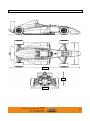
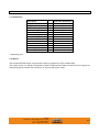
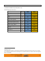
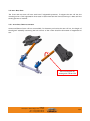
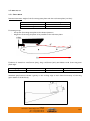
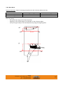
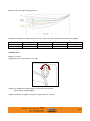
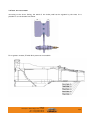
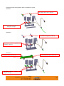
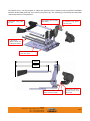
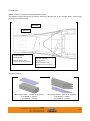
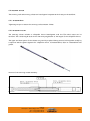
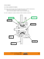
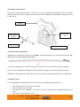
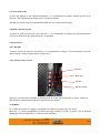
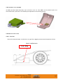
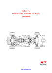
MYGALE M14-F4 FORD MSA FORMULA USER MANUAL MYGALE Technopole 58470 Magny-Cours France Tel : +33 (0)3 86 21 86 21 Fax : +33 (0)3 86 21 86 22 Version: V1.4 0.0 CONTENT 0.0 CONTENT ....................................................................................................... 2 1.0 CAR VIEWS ..................................................................................................... 3 2.0 CAR SPECIFICATIONS ........................................................................................ 4 2.1 Dimensions .................................................................................................... 4 2.2 Weight ........................................................................................................ 4 2.3 Supplied Parts: Partners ..................................................................................... 5 3.0 SET UP AND OPTIONS ........................................................................................ 6 3.1 Geometry information (in baseline set-up) .................................................................. 6 3.2 Set Up Adjustment ........................................................................................... 7 3.3 Kinematics – Graphical Representation ..................................................................... 18 3.4 Springs ....................................................................................................... 22 3.5 Dampers...................................................................................................... 23 3.6 Anti-Roll Bars ............................................................................................... 25 3.7 Aero Set Up ................................................................................................. 27 3.8 Brake bias ................................................................................................... 29 3.9 Pedal box adjustment ....................................................................................... 30 3.10 Set-up sheet Baseline Proposal ........................................................................... 34 3.11 Ballast ...................................................................................................... 35 3.12 Paddle shift ................................................................................................ 36 3.13 Gear box ratios ............................................................................................ 38 3.14 Data acquisition ............................................................................................ 39 3.15 Brake pads ................................................................................................. 39 3.16 Steering system adjustments ............................................................................. 39 3.17 Radiator protection grille .................................................................................. 40 4.0 ASSEMBLY AND MAINTENANCE ............................................................................ 41 4.1 Engine ........................................................................................................ 41 4.2 Transmission ................................................................................................. 41 4.3 Steering System ............................................................................................. 43 4.4 Hub Assembly................................................................................................ 45 4.5 Bottom Front Wishbones .................................................................................... 46 4.6 Wheel Cables ................................................................................................ 46 4.7 Heat protection.............................................................................................. 47 4.8 Brake line protection ........................................................................................ 47 4.9 Electricity.................................................................................................... 47 4.10 Wings ....................................................................................................... 47 4.11 Head restraint ............................................................................................. 48 4.12 Monocoque Chassis and Crash Boxes ...................................................................... 48 4.13 Bodywork repairs ........................................................................................... 49 4.14 Bodywork adjustment ...................................................................................... 49 4.15 Extractible seat ............................................................................................ 49 4.16 Fire extinguisher ........................................................................................... 50 4.17 Markings and holograms ................................................................................... 50 4.18 Screws ...................................................................................................... 50 4.19 Fuel system ................................................................................................. 51 4.20 Cooling system .............................................................................................. 52 4.21 Filling fluids ................................................................................................ 55 4.22 Accident data recorder .................................................................................... 56 4.23 Exploitation tools ........................................................................................... 56 5.0 ANNEXES ...................................................................................................... 60 5.1 Tightening torques (general) ................................................................................ 60 5.2 Tightening torques (F4 mounting): .......................................................................... 61 MYGALE Technopole - 58470 Magny-Cours - France Tel : +33 (0)3 86 21 86 21 Fax : +33 (0)3 86 21 86 22 2/62 1.0 CAR VIEWS 4341 958 1738 MYGALE Technopole - 58470 Magny-Cours - France Tel : +33 (0)3 86 21 86 21 Fax : +33 (0)3 86 21 86 22 3/62 2.0 CAR SPECIFICATIONS 2.1 DIMENSIONS Description Length Height Front ride height Rear ride height Wheelbase Front overhang Rear overhang Front overall width Rear overall width Front track Rear track Front wing assy width Rear wing assy width mm mm mm mm mm mm mm mm mm mm mm mm mm Reference Dimensions 4341 958 20 30 2742 1000 600 1725 * 1715 * 1493.5 1430.4 1400 898 * depending tyres 2.2 WEIGHT The minimum allowed weight is specified by sporting regulations of the championship. The weight of the car should be adjusted by mean of appropriate ballast to ensure that the specified minimum weight is reached with the driver at any time during the event. MYGALE Technopole - 58470 Magny-Cours - France Tel : +33 (0)3 86 21 86 21 Fax : +33 (0)3 86 21 86 22 4/62 2.3 SUPPLIED PARTS: PARTNERS Gearbox, driveshaft: Sadev Steering rack: Titan Springs, dampers: Sachs Fuell cell, fuel pump: Premier Fuel Brake pads: Ferrodo Brake discs, callipers: Brembo Extinguisher : OMP Harness : TRS Motrosports Rims : Team Dynamics MYGALE Technopole - 58470 Magny-Cours - France Tel : +33 (0)3 86 21 86 21 Fax : +33 (0)3 86 21 86 22 5/62 3.0 SET UP AND OPTIONS 3.1 GEOMETRY INFORMATION (IN BASELINE SET-UP) The standard set up of the car is: dimension FRONT REAR Ride Height mm 24 37 Camber deg -3.3 -2.2 Toe deg 0.00 0.00 Castor deg 8.21 -22.81 Castor Offset (wheel centre) mm 5.64 --- Castor Offset (ground) mm 31.23 --- King Pin deg 15.46 --- King Pin Offset (wheel centre) mm 69.1 --- King Pin Offset (ground) mm 15.4 --- Damper-Spring / Wheel ratio 0.68 0.71 Anti Roll Bar (deg) / Wheel ratio 0.69 0.48 % 14.45 22.13 deg 19.9 --- mm 17.8 34.5 mm 30.87 --- Anti Dive Ackermann Roll Center Z Mechanical Trail 1 1 Mechanical Trail The perpendicular distance in side elevation between the steering axis and the centre of tyre contact. It is considered positive when the steering axis is forward of the tyre contact centre and negative when it is rearward. MYGALE Technopole - 58470 Magny-Cours - France Tel : +33 (0)3 86 21 86 21 Fax : +33 (0)3 86 21 86 22 6/62 3.2 SET UP ADJUSTMENT Values are theoretical, assembly dispersion is possible. 3.2.1 RIDE HEIGHT CHECK & ADJUSTMENT The reference points for calculating the ride height are shown below. The vehicle reference plane is the lower side of the wood floor. The skid block is below this. The choice of ride height needs to take account of the skid block thickness which is a maximum of 5mm below the reference plane (and minimum 2mm). The diagrams refer to the dimensions from the chassis reference point to the reference plane. At the front two ride height adjustment screws (F.41.35.001) must be fix on the two reference pads which are machined into the upper surface of the monocoque and are accessible with the damper cover removed. At the rear the reference surfaces are machined pads on the gearbox upper surface, at the level of the damper bracket and are accessible with the engine cover removed. Front reference Rear reference The front reference dimension A1 is 441mm. The rear reference dimension A2 is 369mm. MYGALE Technopole - 58470 Magny-Cours - France Tel : +33 (0)3 86 21 86 21 Fax : +33 (0)3 86 21 86 22 7/62 B1 A1 165 B2 441 230 A2 X1 369 X2 b To set up front and rear ride height values at the level of the front and rear axle centre lines (H1 and H2 respectively), use the following calculation: X1 = A1*cos(α) - B1*sin(α) + H1 X2 = A2*cos(α) + B2*sin(α) + H2 (Dimensions in mm) Where α is the car pitch angle, α = arcsin((H2-H1)/2741.6 in rad. MYGALE Technopole - 58470 Magny-Cours - France Tel : +33 (0)3 86 21 86 21 Fax : +33 (0)3 86 21 86 22 8/62 Ride height adjustment: Front ride height adjustment Rear ride height adjustment Lengthen adjuster to raise car. Shorten adjuster to lower car Lengthen adjuster to raise car. Shorten adjuster to lower car Front: Lengths (ball centre to ball centre) for a 20mm ride height: Pushrod 554.6mm. 1 face on the adjuster changes the ride height by 0.95mm. 1 turn on the adjuster changes the ride height by 5.70mm. For 1mm ride height, 1/6 turn on the adjuster. Rear: Lengths (ball centre to ball centre) for a 30mm ride height: Pushrod 527.5mm. 1 face on the adjuster changes the ride height by 1.00mm. 1 turn on the adjuster changes the ride height by 6.00mm. For 1mm ride height, 1/6 turn on the adjuster. MYGALE Technopole - 58470 Magny-Cours - France Tel : +33 (0)3 86 21 86 21 Fax : +33 (0)3 86 21 86 22 9/62 3.2.2 CASTOR CHECK & ADJUSTMENT The castor angle is the angle, in side elevation, between the steering axis and the vertical. It is considered positive when the steering axis is inclined rearward. You can check the castor angle in the same way in the front and in the rear suspension. The castor angle can be calculated as follows: Measure the angle of the steering arm plane for the front (or the wishbone mount plane for the rear) to the horizontal; this is the measured castor angle (MCA). Positive inclined down to rear, negative inclined down to front. Calculate the true castor angle (TCA) as following: MCA MCA Horizontal and vertical lines TCA Car direction True castor angle Base settings Base set up length, wishbone ball centre to ball centre TCA Front Castor Angle = MCA + 7.08° 8.21° Rear Castor Angle = MCA - 25.41° -22.81° 556.4mm 578.9mm The Castor angle influences the Castor Offset, the Mechanical Trail and therefore the force to turn the wheel. Castor Offset, (mm) The distance in side elevation between the point where the steering axis intersects the ground, and the centre of tyre contact. The offset is considered positive when the intersection point is forward of the tyre contact centre and negative when it is rearward. (Base setting: FRT=31.23mm) Mechanical Trail, (mm) The perpendicular distance in side elevation between the steering axis and the centre of tyre contact. It is considered positive when the steering axis is forward of the tyre contact centre and negative when it is rearward. (Base setting: FRT=30.87mm) The Castor Offset is along the ground plane while the Mechanical Trail is perpendicular to the steering axis. MYGALE Technopole - 58470 Magny-Cours - France Tel : +33 (0)3 86 21 86 21 Fax : +33 (0)3 86 21 86 22 10/62 Castor adjustment: Adjust the castor angle with the rod end bearings as shown in the following pictures: Front castor adjustment MYGALE Technopole - 58470 Magny-Cours - France Tel : +33 (0)3 86 21 86 21 Fax : +33 (0)3 86 21 86 22 Rear castor adjustment 11/62 3.2.3 CAMBER ADJUSTMENT The Camber Angle is the inclination of the wheel plane to the vertical. It is considered positive when the wheel leans outward at the top and negative when it leans inward. The Camber can be adjusted by releasing the fixing bolts and adding or removing shims between the steering arm and the upright. A change of shim has no influence on the toe setting. Front (Rear similar) Camber shim Steering arm Available shims: Part Number F.41.14.055.A F.41.14.056.A F.41.14.057.A F.41.14.058.A Description Camber shim 1 mm Camber shim 1.5 mm Camber shim 2 mm Camber shim 4 mm Front Recommended base setting: Adjustment: Rear Recommended base setting: Adjustment: -3,3°, 2mm of shim 0.325°/mm 1.5mm for 0.5° -2.2°, 4.5mm of shim (2mm + 1.5mm+1mm) 0.300°/mm 1.5mm for 0.5° MYGALE Technopole - 58470 Magny-Cours - France Tel : +33 (0)3 86 21 86 21 Fax : +33 (0)3 86 21 86 22 12/62 3.2.4 TOE CHECK & ADJUSTMENT The toe angle is the angle between a longitudinal axis of the vehicle and the line of intersection of the wheel plane and the road surface. The wheel is ”toed-in” if the forward portion of the wheel is turned towards a central longitudinal axis of the vehicle, and “toed-out” if turned away. A/2 semi forward track wheel To e B/2 semi rearward track wheel T.A. = Toe Angle Checking the distance between the wheel forward and rearward points in the front suspension is possible to measure the Toe. The Toe can be measured with the following formula: Toe = B/2 – A/2 The correlation between degrees and the value B/2-A/2 is : B/2-A/2 (mm) Toe (deg) 18 3 12 2 6 1 0 0 -6 -1 -12 -2 -18 -3 In this table, negative toe corresponds to “toe out”, positive toe corresponds to “toe In”. The Toe angle can be adjusted with the track rod. MYGALE Technopole - 58470 Magny-Cours - France Tel : +33 (0)3 86 21 86 21 Fax : +33 (0)3 86 21 86 22 13/62 Rear toe adjustment Front toe adjustment Base starting set up lengths for toe adjustment (ball centre to ball centre) Front trackrod assembly: 474.9mm for (toe 0° and 0mm) ±1 turn on the bearing = ±3.84mm ±1 face turn on the bearing = ±0.64mm For 1mm toe: 1.6 faces bearing Rear trackrod assembly: 478.7mm for (toe 0° and 0mm) ±1 turn on the adjuster = ±4.70mm ±1 face turn on the adjuster = ±0.43mm For 1mm toe: 2.4 faces adjuster MYGALE Technopole - 58470 Magny-Cours - France Tel : +33 (0)3 86 21 86 21 Fax : +33 (0)3 86 21 86 22 14/62 3.2.5 SUSPENSION POINTS Front suspension points Fixation points The following picture shows the mandatory position of the front upright points: Ref. F.41.14.063.B (x4) Ref. F.41.14.064.B (x2) Steering arm position Spacer Ref. F.41.14.097.A MYGALE Technopole - 58470 Magny-Cours - France Tel : +33 (0)3 86 21 86 21 Fax : +33 (0)3 86 21 86 22 15/62 Rear suspension points Fixation points Fixation points Fixation points The following picture shows the mandatory position of the rear wishbone brackets: 2nd hole from the bottom Lower position Middle position Upper position MYGALE Technopole - 58470 Magny-Cours - France Tel : +33 (0)3 86 21 86 21 Fax : +33 (0)3 86 21 86 22 16/62 The following picture shows the mandatory position of the rear upright points: Ref. F.41.14.063.B (x4) MYGALE Technopole - 58470 Magny-Cours - France Tel : +33 (0)3 86 21 86 21 Fax : +33 (0)3 86 21 86 22 17/62 3.3 KINEMATICS – GRAPHICAL REPRESENTATION All the following graphs represent the kinematics in standard setup. MYGALE Technopole - 58470 Magny-Cours - France Tel : +33 (0)3 86 21 86 21 Fax : +33 (0)3 86 21 86 22 18/62 MYGALE Technopole - 58470 Magny-Cours - France Tel : +33 (0)3 86 21 86 21 Fax : +33 (0)3 86 21 86 22 19/62 MYGALE Technopole - 58470 Magny-Cours - France Tel : +33 (0)3 86 21 86 21 Fax : +33 (0)3 86 21 86 22 20/62 MYGALE Technopole - 58470 Magny-Cours - France Tel : +33 (0)3 86 21 86 21 Fax : +33 (0)3 86 21 86 22 21/62 Motion ratio Motion ratio (MR) = Damper travel Wheel travel Wheel rate = Spring rate * MR² In baseline position : DAMPER FRONT 0.68 ROLL BAR FRONT 0.69 DAMPER REAR 0.71 ROLL BAR REAR 0.48 3.4 SPRINGS Front and rear suspension springs are common sizes. Part Number Stiffness Stiffness lbs/inch N/mm F.41.14.022.A F.41.14.024.A F.41.14.026.A 600 106 800 141 1000 176 MYGALE Technopole - 58470 Magny-Cours - France Tel : +33 (0)3 86 21 86 21 Fax : +33 (0)3 86 21 86 22 22/62 3.5 DAMPERS 3.5.1 FRONT SUSPENSION DAMPERS The standard front damper is the Sachs F4 non-adjustable front damper, reference F.41.14.103.A. MYGALE Technopole - 58470 Magny-Cours - France Tel : +33 (0)3 86 21 86 21 Fax : +33 (0)3 86 21 86 22 23/62 3.5.2 REAR SUSPENSION DAMPERS The standard rear damper is the Sachs F4 non-adjustable rear damper, reference F.41.14.029.A. MYGALE Technopole - 58470 Magny-Cours - France Tel : +33 (0)3 86 21 86 21 Fax : +33 (0)3 86 21 86 22 24/62 3.6 ANTI-ROLL BARS The front and rear anti-roll bars each have 5 adjustable positions. To adjust the anti-roll bar the retaining screw of the adjustment clevis must be unscrewed and the clevis moved up or down until the setting position is reached. 3.6.1 ANTI-ROLL BARS ADJUSTMENT Various stiffness of anti-roll bar are available. To eliminate pre-load in the anti-roll bar, the length of the adjuster assembly connecting the anti-roll bar to the rocker should be shortened or lengthened to suit. Shorten/lengthen by turning anti-roll bar link MYGALE Technopole - 58470 Magny-Cours - France Tel : +33 (0)3 86 21 86 21 Fax : +33 (0)3 86 21 86 22 25/62 ARB currently available Standart ARB : Ø14 3.6.2 ANTI-ROLL BAR STIFFNESS ARBØ Ø12 Ø14 Ø18 1 221 352 621 (Optionnals ARB : Ø12 and Ø18) Position 3 411 681 1257 2 311 501 912 4 571 928 1764 5 765 1271 2504 N/mm Here the anti-roll bar rate graph from the different anti-roll bar diameters and positions. Anti roll bar rate = f(blade position) (N/mm) 3000 Anti roll bar rate (N/mm) 2500 2000 D12 1500 D14 D18 1000 500 0 0 1 2 3 4 5 6 Blade position (see picture) MYGALE Technopole - 58470 Magny-Cours - France Tel : +33 (0)3 86 21 86 21 Fax : +33 (0)3 86 21 86 22 26/62 3.7 AERO SET UP 3.7.1 FRONT WING Position Convention: Angle of the front wing main plate with the reference plane (red line): Front wing -3° -5°/+2° Standard position Range Front wing set up: - Set up the front wing main plate at the desired position - Adjust the front wing end plate to be parallel to the reference plane 6.5mm -3° Frt Ref plane Rr Evolution of downforce coefficient (SCz), drag coefficient (SCx) and balance with front wing main plane angle: Delta wing angle +1° Delta SCx - Delta SCz +0.06 Delta balance +4.6% Standard specification includes a gurney on the trailing edge on each lateral extremity of the wing (part number F.41.24.009.A). MYGALE Technopole - 58470 Magny-Cours - France Tel : +33 (0)3 86 21 86 21 Fax : +33 (0)3 86 21 86 22 27/62 3.8.2 REAR WING Position Convention: Angle of the wing main plate with the reference plane (red line): Upper wing +5° 0°/+15° Standard position Range Lower wing 0° 0°/+4° Rear wing set up: - Set up the lower wing at the desired position - Adjust the rear wing end plate to be parallel to the reference plane - Set up the upper wing at the desired position by using the adjusting holes +5° Frt Ref plane Rr 0° 12.9mm Frt MYGALE Technopole - 58470 Magny-Cours - France Tel : +33 (0)3 86 21 86 21 Fax : +33 (0)3 86 21 86 22 Ref plane Rr 28/62 Details on the rear upper wing positions: Evolution of downforce coefficient (SCz), drag coefficient (SCx) and balance with rear wing angles: Upper wing Lower wing Delta wing angle +2.5° +1° Delta SCx +0.006 +0.001 Delta SCz +0.034 +0.011 Delta balance -2.5% -0.8% 3.8 BRAKE BIAS Range: 17.5 turns Adjustment: more front brake = turn left A spacer is available as optional part for the brake bias control: - F.41.11.057.A: Length 100mm Teams are allowed to adjust its length to optimize driver comfort. MYGALE Technopole - 58470 Magny-Cours - France Tel : +33 (0)3 86 21 86 21 Fax : +33 (0)3 86 21 86 22 29/62 3.9 PEDAL BOX ADJUSTMENT According to the driver feeling, the width of the brake pedal can be adjusted by the team. It is possible to cut the shaded area below: For ergonomic reasons, 5 Pedal Box’s positions are available: MYGALE Technopole - 58470 Magny-Cours - France Tel : +33 (0)3 86 21 86 21 Fax : +33 (0)3 86 21 86 22 30/62 Each position has an equipment which is available in option. Position 1: F.41.11.029.B Short spacer pedal stop F.41.11.017.C Master cylinder rod prolongator, setting 1 Position 2: F.41.11.056.A Long spacer pedal stop F.41.11.018.C Master prolongator, setting 2 cylinder rod Position 3: F.41.11.031.A Short pedal stop rest bF.41.11.019.C Master prolongator, setting 3 cylinder F.41.11.029.B Short spacer pedal stop rod MYGALE Technopole - 58470 Magny-Cours - France Tel : +33 (0)3 86 21 86 21 Fax : +33 (0)3 86 21 86 22 31/62 Position 4: F.41.11.031.A Short pedal stop rest F.41.11.056.A Long spacer pedal stop F.41.11.020.C Master prolongator setting 4 cylinder rod Position 5: F.41.11.032.A Long pedal stop rest F.41.11.056.A Long spacer pedal stop F.41.11.021.C Master prolongator, setting 5 cylinder rod The throttle cable must be cut at the right length once the pedal box is correctly positioned for the driver. Long pedal stop rest reinforcement: Welded reinforcements in the corners done by teams to stiffen the long pedal stop rest are allowed, in areas illustrated in picture: MYGALE Technopole - 58470 Magny-Cours - France Tel : +33 (0)3 86 21 86 21 Fax : +33 (0)3 86 21 86 22 32/62 For small drivers, it is also possible to offset the pedal box more rearward, with a maximum of 450mm between brake pedal plate and front end of the monocoque. The following picture shows the maximum rearward position of the pedal box: F.41.11.062.A Spacer pedal stop 215mm F.41.11.032.A Long pedal stop rest F.41.11.060.A Long spacer throttle pedal F.41.11.061.A Master cylinder rod prolongator 300mm F.41.11.059.A Fixing plate, pedal box offset 450mm 340mm F.41.21.106.A Bush, throttle sensor, pedal box offset MYGALE Technopole - 58470 Magny-Cours - France Tel : +33 (0)3 86 21 86 21 Fax : +33 (0)3 86 21 86 22 F.41.21.105.A Bracket, throttle sensor, pedal box offset 33/62 3.10 SET-UP SHEET BASELINE PROPOSAL SET-UP SHEET M14-F4 Car Date Circuit Run FRONT REAR LH RH LH RH Weight Included / not included Per wheel Total Weight distribution Kg Kg % Ride height mm 19 30 Geometry Camber ° 3,3 3 2.2 2.2 Camber shims Toe per wheel (in+/out-) Castor mm mm ° 1 8.2 1 8.2 1 -22.8 1 -22.8 Wheelbase Track mm mm 2742 1725 1715 Sachs non adjustable Sachs non adjustable Suspensions Pushrod position Dampers Type Bump Rebound pos pos Springs Stiffness Preload lbs/in mm Anti-roll bar Diameter mm Blade set-up mm Tyres Type Pressure - cold Pressure - hot bar bar 800 4.7 800 4.7 800 0 3 3 800 0 14 3 14 3 Brakes Master cylinder Balance Pads 0,625 0,75 % DS PERFO DS PERFO DS PERFO DS PERFO Wings Angle Gurney ° -3 10x345 5 (top) / 0 (beam) Clutch Master cylinder 0.75 Gearbox Crownwheel & pinion 10/31 1st 2nd 3rd 4th 5th 6th 14/37 18/35 18/28 21/27 20/22 27/26 Cooling Radiator blanking % Comments MYGALE Technopole - 58470 Magny-Cours - France Tel : +33 (0)3 86 21 86 21 Fax : +33 (0)3 86 21 86 22 34/62 3.11 BALLAST Ballast is used to reach the minimum allowable weight Two ballast fixing locations are provided: inside the splitter and in the cockpit under driver’s legs (bottom view of monocoque). 970.9mm 512.6mm Cockpit ballast fixing points Maximum allowed: 16Kg (bracket and screws included) Splitter ballast fixing points Maximum allowed: 6.5Kg (bracket and screws included Standard ballasts: Monocoque ballast – cockpit (5 Kg/plate) F.41.18.008.A - ballast F.41.18.010.A – bracket MYGALE Technopole - 58470 Magny-Cours - France Tel : +33 (0)3 86 21 86 21 Fax : +33 (0)3 86 21 86 22 Monocoque ballast – splitter (2 Kg/plate) F.41.18.011.A - ballast F.41.18.012.A - bracket 35/62 3.12 PADDLE SHIFT 3.12.1 PADDLE SHIFT USER MANUAL - To engage 1st gear (when neutral “N” is displayed on the dashboard) push Neutral (N) together with shift paddle “UP”. Push « UP » Push « N » - To return to neutral (when 1st gear “1” is displayed on the dashboard) push Neutral (N) together with shift paddle “DOWN”. Pull « DOWN » Push « N » MYGALE Technopole - 58470 Magny-Cours - France Tel : +33 (0)3 86 21 86 21 Fax : +33 (0)3 86 21 86 22 36/62 - To shift into reverse (when neutral “N” is displayed on the dashboard) push Neutral (N) together with shift paddle “DOWN”. Pull « DOWN » Push « N » 3.12.2 GEAR-SHIFT PNEUMATIC JACK Rod position on gear-shift pneumatic jack may have to be adjusted: Due to parts manufacturing tolerances, to have the right rod position setting to avoid gear-shift issue, you may have to adjust following distance from 26.5 to 25 mm MYGALE Technopole - 58470 Magny-Cours - France Tel : +33 (0)3 86 21 86 21 Fax : +33 (0)3 86 21 86 22 37/62 3.13 GEAR BOX RATIOS The standard Differential: CWP ratio: Gear ratios: gearbox build specification is: free (open with no limited slip) 10/31 1st 14/37 2nd 18/35 3rd 18/28 4th 21/27 5th 20/22 6th 27/26 The gear ratios are drawn on the following graph: 8000 Revs (tr/min) 7000 6000 5000 4000 3000 0 50 100 150 200 250 200 250 Speed (km/h) Shot gear ratios are available in option: Gear ratios (option): 4th 22/29 5th 24/28 6th 22/23 8000 Revs (tr/min) 7000 6000 5000 4000 3000 0 50 100 150 Speed (km/h) MYGALE Technopole - 58470 Magny-Cours - France Tel : +33 (0)3 86 21 86 21 Fax : +33 (0)3 86 21 86 22 38/62 3.14 DATA ACQUISITION The following sensors are included in the data acquisition kit: - Steering angle Front wheels speed Acceleration in 3 axes Front and rear brake pressure Lap timer Gear Throttle pedal Smarty camera 3.15 BRAKE PADS The standard fit brake pads are the Ferrodo DS performance, reference F.41.17.004.A are identical front and rear. Other brake pads are available in option: -Ferrodo DS3000 (reference F.41.17.007.A). -Ferrodo DS1.11 (reference F.41.17.008.A). New brake pads must always be bedded following Ferrodo bedding recommendation. Heating gradually stepwise, until minimum 500°C is reach. Master cylinder reservoir extensions are allowed. 3.16 STEERING SYSTEM ADJUSTMENTS The height of the steering column can be adjusted by changing the position of the bracket on the monocoque. Adjustment In addition to the standard steering column, a longer steering column is available as optional part: - F.41.16.001.B: Standard length - F.41.16.046.A: Length +80mm MYGALE Technopole - 58470 Magny-Cours - France Tel : +33 (0)3 86 21 86 21 Fax : +33 (0)3 86 21 86 22 39/62 Spacers for the steering wheel are also available as optional parts to adjust the longitudinal position of the steering wheel (reference F.41.16.003.B). It is also possible to cut the steering rack stop to adjust maximum steering angle: 3.17 RADIATOR PROTECTION GRILLE Radiator grille protections are available as optional parts: - Right grille: F.41.26.081.A - Left grille: F.41.26.082.A MYGALE Technopole - 58470 Magny-Cours - France Tel : +33 (0)3 86 21 86 21 Fax : +33 (0)3 86 21 86 22 40/62 4.0 ASSEMBLY AND MAINTENANCE Note: all safety critical components should be checked regularly. 4.1 ENGINE Individual engine lease contracts must be adhered to. 4.2 TRANSMISSION 4.2.1 GEAR BOX The Sadev SL75-14 LW F4 gearbox is homologated for use in the Mygale M14-F4. No other gearboxes have passed a rear impact crash test. Clutch shaft specification depends on the gearbox manufacturer and the type of engine. For all information regarding build and maintenance gearbox, customers should refer to the Sadev user manual. 4.2.2 CLUTCH In production, a batch of clutch release spacer F.41.12.076.B has been drilled on the wrong side in a first time, and has two useless holes (see in red on following drawing). Only this batch, with the marking 028-15, is allowed with these supplementary holes. MYGALE Technopole - 58470 Magny-Cours - France Tel : +33 (0)3 86 21 86 21 Fax : +33 (0)3 86 21 86 22 41/62 4.2.3 DRIVE SHAFT The standard fit driveshaft is supplied by Sadev. For safety reasons, right and left driveshafts must not be inverted. Driveshaft angles are given for 2.5° negative camber, face viewed. It appeared that under certain circumstances, driveshaft CV boots diameter can expand too much with centrifugal forces and be damaged rubbing the pushrod. It is recommended to use lockwire inside each groove of the boot, as per photo below, in order to contain its expansion and avoid any damage. MYGALE Technopole - 58470 Magny-Cours - France Tel : +33 (0)3 86 21 86 21 Fax : +33 (0)3 86 21 86 22 42/62 4.3 STEERING SYSTEM The steering rack and steering column are homologated components which may not be modified. 4.3.1 STEERING RACK Tightening torque to ensure the steering rack movement: 34Nm 4.3.2 STEERING COLUMN The steering column includes a collapsible device homologated with the FIA which must not be modified. The column length must not be altered by adjustment of the length of the collapsible device. The upper and lower parts of the column are joined by a splined sliding section, held together axially by a capscrew which tightens against the collapsible device. If disassembled, must be reassembled with grease. Section of the steering column assembly: MYGALE Technopole - 58470 Magny-Cours - France Tel : +33 (0)3 86 21 86 21 Fax : +33 (0)3 86 21 86 22 43/62 4.3.3 STEERING COLUMN JOINT For safety reasons, it is recommended to thoroughly inspect the steering column joint after each shock or crash. 4.3.4 STEERING WHEEL GLASS When removing the steering wheel some drivers or mechanics may push the glass with their fingers. Be careful, pushing too hard could break the sealing and cause glass damage. MYGALE Technopole - 58470 Magny-Cours - France Tel : +33 (0)3 86 21 86 21 Fax : +33 (0)3 86 21 86 22 44/62 4.4 HUB ASSEMBLY 4.4.1 FRONT AND REAR HUB ASSEMBLY The uprights, wheel bearings, wheel drive pegs and lock nuts are identical front and rear. - At the front the front stud is fitted in the wheel bearing. - At the rear the driveshaft is fitted directly in the wheel bearing. It is not recommended to engage the wheel nuts with a pneumatic screwdriver. Loctite 270 Loctite 270 Wheel peg Wheel stud Wheel bearing Upright Brake disc MYGALE Technopole - 58470 Magny-Cours - France Tel : +33 (0)3 86 21 86 21 Fax : +33 (0)3 86 21 86 22 45/62 4.4.2 WHEEL SPEED SENSOR Provision for wheel speed sensors is made on the front uprights (data acquisition kit). The speed sensor bracket and disc are respectively references F.41.21.003.B and F.41.21.004.A. The spacer ref is F.41.21.079.A. Upright Speed sensor disc Speed sensor bracket Speed sensor Speed sensor spacer 4.5 BOTTOM FRONT WISHBONES Wishbones are usable only when they are straight. If flexion (distance A on the drawing below) is over than 1mm, the wishbone must not be used. To avoid the flexing, do not ratchet strap the car in the truck, do not lift the car by the wishbone. In the case of a damaged ball, Mygale proposes a staking bearing joint replacement (F.41.14.121.A). Wishbone primary ball joint is glued with Loctite in its housing, and must be heated for disassembling. 4.6 WHEEL CABLES It is recommended to replace cables if one or more of the following conditions is met: The cable has been on the car for 12 months The car has been in an accident The cable has been damaged, i.e. the braid, tape or mould have been damaged exposing the fibre The cable or cover has been cut out MYGALE Technopole - 58470 Magny-Cours - France Tel : +33 (0)3 86 21 86 21 Fax : +33 (0)3 86 21 86 22 46/62 4.7 HEAT PROTECTION To avoid any damage to the composite bodywork, it is recommended to install a thermal protection on the floor, the sidepod and the engine cover around the exhaust. Thermal protection is also recommended between the monocoque and the engine. 4.8 BRAKE LINE PROTECTION To ensure a good protection for the brake line, it is recommended to replace the heat shrink sheat covering in the area of the wishbone when it is damaged. 4.9 ELECTRICITY 4.9.1 BATTERY To ensure a good life time for the battery, it is recommended to charge it at the reception of the car and to charge it every 6 month when you don’t use it. 4.9.2 COCKPIT SWITCH PLATE Starter Rain light Ignition Master switch Spacers F.41.21.104.A are available as optional parts to offset the switch plate of 70mm. Teams are also allowed to reduced their lengths to optimize driver comfort. 4.10 WINGS For reliability reasons, it is highly recommended to replace the wings every two years. Moreover, it is also recommended to check the wings regularly in order to detect the potentially damaging effects of small hits or contacts on the endplates. MYGALE Technopole - 58470 Magny-Cours - France Tel : +33 (0)3 86 21 86 21 Fax : +33 (0)3 86 21 86 22 47/62 To avoid matting or weaken the front wing mounts, it is recommended to tighten them moderately on the crashbox, and to use the medium washer specified in the parts catalogue. 4.11 HEAD RESTRAINT The head restraint must be properly assembled, with the fixations clipped securely. The head restraint must never be able to move freely. According to the regulations, it is not permitted to cover the head restraint with any material other than paint. In the case of a damaged Head Restraint, the aramid skin replacement by Mygale is available (ref.: F.41.19.060.A). 4.12 MONOCOQUE CHASSIS AND CRASH BOXES Monocoque chassis and crash boxes reparations must be performed by an approved entity. Before any modification or reparation, you must contact Mygale. However, the team is allowed to change the nose cap. The nose cap must be properly assembled, with the fixations clipped securely on the main part of the crash box. Moreover, it is important to stick the nose cap on the crash box with four silicone points. MYGALE Technopole - 58470 Magny-Cours - France Tel : +33 (0)3 86 21 86 21 Fax : +33 (0)3 86 21 86 22 48/62 4.13 BODYWORK REPAIRS Teams are allowed to repair fibre glass bodywork components but the total surface of repaired areas must not be more 10% of the total surface of the part. If you have some doubt, don’t hesitate to contact Mygale 4.14 BODYWORK ADJUSTMENT To optimize sidepod adjustment, brackets on the floor and on the side of the monocoque can be adjusted. For the engine cover, brackets on the rear face of the monocoque, on the rear roll hoop and on the gearbox can be adjusted. Adjustable brackets are in red on the following drawing: 4.15 EXTRACTIBLE SEAT Extractible seat cut for loom: In order to position correctly the extractable seat, it is allowed to make a local cut in the seat in the area of the chassis loom. Reinforcement washers: It is allowed to glue steel washers around the bottom location holes in order to reinforce the area. MYGALE Technopole - 58470 Magny-Cours - France Tel : +33 (0)3 86 21 86 21 Fax : +33 (0)3 86 21 86 22 49/62 4.16 FIRE EXTINGUISHER The fire extinguisher must be fitted in its support in the monocoque. Be sure that it is solidly attached by its retainer. ffExtinguisher Support An interior pull handle cable is located on the right of the steering wheel. The exterior cable is located on the right of the rear rollover structure, and also activates the main master switch. Do not forget to add extinguisher and electrical switch stickers in this area, according to regulation. Eventually, Mygale proposes an extinguisher refill (ref: F.41.19.059.A). A spacer F.41.19.061.A of 70mm is available as option in order to make the extinguisher cable handle easier to reach for the driver. Its length can be reduced by 24mm on the hole side of the spacer. 4.17 MARKINGS AND HOLOGRAMS Laser markings and holograms stickers must stay always visible and in any case must not be covered by painting or sticker. Furthermore, the holograms stickers must not be removed. 4.18 SCREWS The screws which are classified as type 2 can be modified but must keep the same class and dimensions as specified in the spares parts catalogue. Concerned screws are those related to safety components: - Front crashbox - Rear roll hoop - Rear crashbox/rear wing mount - Seat belt - Shoulder belt bracket MYGALE Technopole - 58470 Magny-Cours - France Tel : +33 (0)3 86 21 86 21 Fax : +33 (0)3 86 21 86 22 50/62 4.19 FUEL SYSTEM 4.19.1 FUEL TANK The fuel tank matches with the FIA specifications. All required details are issued in the certificate of compliance. (i.e. date of validation) It is recommended to regularly wash the inside of the fuel tank to ensure there is no dirt in the fuel circuit. Mygale advises the team to clean the fuel cell and the fuel system after the first uses. 4.19.2 DRAIN Do not use the car’s fuel pump to drain the tank. It is advisable to use an external pump in order to avoid damaging the on-board unit. An external pump can be attached to the drain hole by removing the dash cap on the fuel tank plate. It is also necessary to open the filler cap while draining. Be careful not to damage the thread by over tightening the cap Capacity: 48 litres IN DRAIN OUT 4.19.3 FUEL ASSEMBLY The fuel pump assembly is composed of the fuel pump with its connector inside the fuel tank buffer body and two 5 bar pressure regulators. In the bottom of the body are 3 check valves to fill the body with fuel. When remounting the pump assembly, take care the pump and filter sock are positioned and attached with rilsan in order to keep free of move the 3 check valves, as illustrated on the following picture. F.41.23.052.A Fuel Filter series F.41.23.039.A 4.5 Bar fuel pressure regulator X2 F.41.23.034.A Fuel pump (250l/h) F.41.23.033.A Fuel tank buffer check valve X3 MYGALE Technopole - 58470 Magny-Cours - France Tel : +33 (0)3 86 21 86 21 Fax : +33 (0)3 86 21 86 22 51/62 4.19.4 SEALING After all the gearbox and electric cables are insert in the monocoque, you must add expanded foam in the passage circled in red so as to ensure a sealing. Expanded Foam 4.20 COOLING SYSTEM 4.20.1 MAIN WATER CIRCUIT In order to make the mounting easier, it is allowed to cut or adjust the length of silicone hoses. It is recommended to add two cut parts of silicone hose D32 around the water tube that is between the two radiators, to get a better maintaining through the monocoque rear face (blue circles). MYGALE Technopole - 58470 Magny-Cours - France Tel : +33 (0)3 86 21 86 21 Fax : +33 (0)3 86 21 86 22 52/62 If necessary, teams can add a paper gasket on the coolant engine inlet. Warning: The right radiator cap must not be used to bleed the circuit. It must be manipulated carefully as the thread in the radiator is fragile. When mounting the cap, it is recommended to use sealing paste and tight moderately. 4.20.2 HEADER TANK CIRCUIT 4.20.3 OIL CIRCUIT Nota: The two extensions surrounded in red on the picture can be cut by the team. MYGALE Technopole - 58470 Magny-Cours - France Tel : +33 (0)3 86 21 86 21 Fax : +33 (0)3 86 21 86 22 53/62 4.20.4 CATCH TANK A catch tank is fitted in the car with its bracket, on the monocoque rear face. To avoid any risk of oil in the water circuit, ensure that the catch tank hoses do not end at the bottom of the catch tank. The recommended position of hoses is at the middle height of the catch tank (see following picture). 4.20.5 AIR CIRCUIT In order to make the mounting easier, it is allowed to cut or adjust the length of silicone hoses. MYGALE Technopole - 58470 Magny-Cours - France Tel : +33 (0)3 86 21 86 21 Fax : +33 (0)3 86 21 86 22 54/62 4.21 FILLING FLUIDS The recommended quantities must always be respected. Designation Quality Quantity 10W40 or 10W50 6L Gear box Oil 75W140 1.3 L Water cooling Anti freeze 5L (50% extract – 50% water) Brake fluid / Clutch release fluid - 2L Fuel Unleaded 98 or 95 48 L Engine Oil MYGALE Technopole - 58470 Magny-Cours - France Tel : +33 (0)3 86 21 86 21 Fax : +33 (0)3 86 21 86 22 55/62 4.22 ACCIDENT DATA RECORDER An ADR (Accident Data Recorder) can be fitted in the car. This ADR can be mounted under the extractable seat (reference F.41.19.030.A) as explained on the following picture. 4.23 EXPLOITATION TOOLS 4.23.1 JACK BAR About the teams who want to build their own jack bar, Mygale provides some dimensions to them. FRONT DIMENSIONS Front Wing MYGALE Technopole - 58470 Magny-Cours - France Tel : +33 (0)3 86 21 86 21 Fax : +33 (0)3 86 21 86 22 56/62 REAR DIMENSIONS Rear jack plate MYGALE Technopole - 58470 Magny-Cours - France Tel : +33 (0)3 86 21 86 21 Fax : +33 (0)3 86 21 86 22 57/62 Mygale also proposes its own jack bars. These ones are available on the spare parts catalogue: Front jack bar (F.41.35.008) Rear jack bar (F.41.35.020) 4.23.2 SET UP TOOLS Some basic set-up tools are for sale on the spare parts catalogue. Tools to adjust parallelism are available: Front parallelism bar (F.41.35.026) Rear parallelism bar (F.41.35.027) We also propose false wheels which help you to set your car. The height of this part is adjustable so as to simulate your real wheel. False wheel (F.41.35.066) Height adjusters can be insert there The references of the adjusters are: - 1mm adjuster: F.41.35.032 -2 mm adjuster: F.41.35.035 -3 mm adjuster: F.41.35.033 MYGALE Technopole - 58470 Magny-Cours - France Tel : +33 (0)3 86 21 86 21 Fax : +33 (0)3 86 21 86 22 58/62 4.23.3 VARIOUS TOOLS Mygale is able to propose useful tools like: Body support trestles (F.41.35.054) Steering wheel support (F.41.35.127) Fuel filler cask (F.41.35.105) and it support (F.41.35.110) Holding key (F.41.35.060) and socket to fix your wheels studs (F.41.35.124) MYGALE Technopole - 58470 Magny-Cours - France Tel : +33 (0)3 86 21 86 21 Fax : +33 (0)3 86 21 86 22 59/62 5.0 ANNEXES 5.1 TIGHTENING TORQUES (GENERAL) General guideline for tightening torques for steel bolts: METRIC C o a r s e T h r e a d B ol t Thread Pitch M4 0.7 M5 0.8 M6 1 M8 1.25 M10 1.5 M12 1.75 M14 2 F i n e T h r e a d B ol t Thread Pitch M8 M10 M10 M12 M12 M14 M16 M18 M20 IMPERIAL 1.0 1.0 1.25 1.25 1.5 1.5 1.5 1.5 1.5 Thread Pitch 1/4 5/16 3/8 7/16 1/2 9/16 5/8 28 TPI 24 TPI 24 TPI 20 TPI 20 TPI 18 TPI 18 TPI 8.8 Torque Nm 2.5 4.9 8.4 20 40 70 110 10.9 Torque Nm 3.5 6.9 11.9 28 55 100 150 12.9 Torque Nm 4.2 8.3 14 34 65 115 180 8.8 Torque Nm 22 44 42 75 70 120 180 260 360 10.9 Torque Nm 30 62 59 105 100 170 250 370 510 12.9 Torque Nm 36 75 72 130 120 200 300 440 610 Grade 5 Torque Lbs-ft 7 14 25 40 60 85 120 Grade 8 Torque Lbs-ft 10 20 35 55 85 120 170 These values should be used where a different torque value is not specified. This data refer to a friction coefficient = 0.1 (lubricated). For different friction values the data can change considerably. For example, considering a friction of 0.14 the preload will decrease by about 7% while the torque force will increase about 25%. Conversion factors: Lbs-ft x 1.356 = Nm Nm x 0.7376 = Lbs-ft MYGALE Technopole - 58470 Magny-Cours - France Tel : +33 (0)3 86 21 86 21 Fax : +33 (0)3 86 21 86 22 60/62 5.2 TIGHTENING TORQUES (F4 MOUNTING): TIGHTENING TORQUES Désignation Size Tightening torque N.m Notes m.Kg (x9.81) Lb.Ft (x par 7.246) Wheel – Suspension - Upright Wheel nut 20 x 1.00 200 20.4 147.5 Wheel peg 12 x 1.5 115 11.7 85 Loctite Wheel bearing 12 x 1.5 115 11.7 85 Loctite Rocker bolts 10 x 1.5 65 6.6 48 Lower wishbone outer bearing 3/8-24 UNF 35 3.6 26 Suspension bearings 8 x 1.25 34 3.5 25 Suspension brackets 8 x 1.25 34 3.5 25 Wheel cables 8 x 1.25 34 3.5 25 Gear box / clutch / Bell housing Clutch 8 x 1.25 34 3.5 25 Bell housing lower 12 x 1.75 115 11.7 85 Bell housing upper 10 x 1.5 65 6.6 48 Gearbox 10 x 1.5 65 6.6 48 7.1 52 Brake Calliper bolt 10 x 1.5 70 Engine Lower engine fitting 10 x 1.5 65 6.6 48 Upper engine fitting 8 x 1,25 34 3.5 25 MYGALE Technopole - 58470 Magny-Cours - France Tel : +33 (0)3 86 21 86 21 Fax : +33 (0)3 86 21 86 22 61/62 COMPONENTS LIFE CYCLE AND GUARANTEE The components of this vehicle have a limited life cycle and it returns to the holder to assure the maintenance and checking. The maximum mileage of the parts is set to one season (tests and races), and after this period, Mygale recommends to replace all the parts exposed to a possible fatigue weakening. It is strongly recommended to replace all the parts that could be affected / damaged after a major crash or accident. The wear parts have to be replaced according to the holder’s appreciation. Moreover, all the "competition" parts cannot be covered by any contractual guarantee. MYGALE CONTACT LIST Web site: www.mygale.fr Parts sales: [email protected] Technical information: [email protected] Telephone: +33 (0)386 21 86 21 Fax : +33 (0)386 21 86 22 MYGALE Technopole - 58470 Magny-Cours - France Tel : +33 (0)3 86 21 86 21 Fax : +33 (0)3 86 21 86 22 62/62