1
3.1 - NOISE SUPPRESSION DIODE INSTALLATION
FOR ELECTRIC OVER AIR SHIFT SOLENOIDS
Installation Instructions for SCHNITZ IGNITION CONTROLLERS with AUTO-SHIFT.
1 - PRO-STREET, Connect this way ONLY if the Shift Light Output is being
used for Auto-Shifting.
a - Red Wire to LEFT #1 Terminal, Shift Light Positive
b - Black Wire to Left #2 Terminal, Shift Light Ground
2 - TOP-GAS
a - Red Wire to LEFT #2 Terminal, Shift Output
b - Black Wire to RIGHT #7 Terminal, Ground
3 - TOP-GAS "4"
a - Red Wire to RIGHT #4 Terminal, Switched +12 Volts
b - Black Wire to LEFT #4 Terminal, Shift Solenoid Ground
Installation Instructions for All SCHNITZ AUTO-SHIFTER's
1 - Connect the Noise Suppression Diode RED WIRE to the AUTO-SHIFT
Red Wire that is going to the Shift Solenoid.
2 - Connect the Noise Suppression Diode BLACK WIRE to the AUTO-SHIFT
Blue Wire.
Installation Instructions for all MANUAL SHIFT Electric Over Air Shifter, PRO-MOD & FUNNY-BIKE
1 - Red Wire to Positive(+!2V side) Shift Solenoid Wire.
2 - Black Wire to Shift Solenoid Ground Wire.
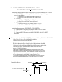
The Noise Suppression Diode should be placed within 6 inches of the Shift
Solenoid. The recommended method for connecting the Diode is as follows.
1 - Strip the Insulation off from the Shift Solenoid wires approx. 6 inches back.
2 - Remove the Spade Terminals from the Diode Wires and remove
approx. 1/2 inche of insulation.
3 - Wrap the Diode RED WIRE around the Shift Solenoid Positive Wire.
4 - Wrap the Diode BLACK WIRE around the Shift Solenoid Ground Wire.
5 - SOLDER these Connections, These connections will fail if they are NOT
soldered.
6 - Cover the connections with Shrink Wrap or Electrical Tape.
7 - Test Shift Solenoid Operation. If the Solenoid will Operate the DIODE
is most likely installed backwards e.g.(Red and Black wires reversed).
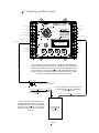
RED WIRE
Example Installation
DIODE
SHIFT
SOLENOID
To Shifter Arming Switch(+12V)
Shift Switch
Page 16
BLACK WIRE
Ground