1
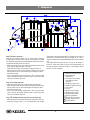
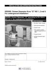
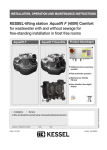
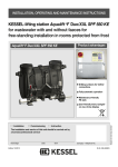
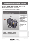
INSTALLATION AND USER’S MANUAL KESSEL SE CN / SE CNS – Self Disposal Grease Separators Size NS 2, 4, 7, 10, 15, 20 and 25 KESSEL SE CN – Self Disposal Grease Separators. Size NS 2, 4, 7, 10, 15, 20 and 25 Product Advantages Low weight offers easy handling and installation Separate disposal of grease and sludge Fully corrosion resistant PE Art.Nr. 99210.00/-41 Edition 03/2012 ID-number 010-076-CN 1. Safety Information All personnel for the installation, assembly, operation, maintenance and repair of this system must have the proper training and qualifications. Proper installation and operation of this system is required. Technical limits of this system may not be exceeded. Observe all local / national norms and safety regulations during the installation, assembly, operation, maintenance and repair of this system. DANGERS WARNING ! NOTICE ! • • • • • Gases and fumes may pose a suffocation, infection and explosion hazard Hazards from falls / slips Drowning Infections from germs and contaminated wastewater Physical and mental strain due to working in dark, tight areas. Not following this operational manual or local / national safety regulations could result to damage of the system, physical injury or even death This system is made up of individual components. During the installation, maintenance, inspection or repair of any of these individual components, the entire system should be shut down before any work is undertaken. This system operates on electrical power and also contains moving parts as well as an electrical heating system. Improperly operating or handling this system could result in damage to the system and / or injury or death to the operation. When the system is initially connected to a power source the sludge pump or the heating elements may immediately begin to operate. Keep away from the separator during the electrical connection. Make sure that the separator is completely installed and all necessary connections are made before the system is connected to power. 2 Table of Contents 1. Safety Information ..................................................................................page 2 Electrical data ...........................................................page Dimensioned drawings SE CN .................................page Dimensioned drawings SE CNS...............................page 4 5 8 wiring diagramm .......................................................page Control unit ..............................................................page Outputs ....................................................................page Control unit settings .................................................page General ....................................................................page Programming the funktions ......................................page Operation .................................................................page Functions/steps of the disposal procedure ..............page Setting parameters ..................................................page 11 12 12 13 13 13 13 13 13 2.1 2.2 3. Technical data 3.1 3.2 Application ................................................................page System description ...................................................page 4. Installation and Assembly 4.1 4.2 Installation information..............................................page 10 Assembly ..................................................................page 10 2. General 5.1 5.2 5.3 5.4 5.4.1 5.4.2 5.5 5.6 5.7 5. Electrical connections 6. Commissioning 4 4 ..................................................................................page 14 ..................................................................................page 15 7. Disposal ..................................................................................page 17 8. Malfunction ..................................................................................page 18 9. Maintenance 10. Guarantee ..................................................................................page 21 11. Important contacts/Info ..................................................................................page 22 ..................................................................................page 23 12. Separator characteries 3 2. General 2.1 Application 2.2 System description This grease separator is designed to separator grease and sludge from the wastewater stream of a private or public kitchen. ➀ Inlet DN 150/DA160 mm ➁ Outlet DN 150/DA160 mm ➂ Connection for heating rod (heating road is optional) ➃ Sludge transfer pump ➄Sludge and Grease tank ➅ Control unit ➆ Access ➇ Grease disposal pipe ➈ Sludge disposal pipe ➉ Grease mixing lever Internal ventilation Grease disposal valve Sludge disposal valve Heating dome The outlet of this grease separator can be connected to private or public sewers. The separation of grease and sludge from the wastewater stream is handled by gravity alone. SE NS 7 3. Technical Data 3.1. Electrical data Current: 230 V 50 Hz Total power requirement: 1700 Watt (Heating dome – 1200 Watt (230 V – 50 Hz) (Sludge rinsing pump – 500 Watt (230 V – 50 Hz) Protection class: Fuse requirements: 4 IP 54 10 amp 3. Technical Data SE CN NS 2-7 3.2 Dimensioned drawings SE NS 4 SE NS 2 ➀Inlet DN 150/DA160 mm ➁ Outlet DN 150/ DA160 mm ➂ Connection for heating rod (heating road is optional) ➃ Sludge transfer pump ➄ Sludge and Grease tank ➅ Unit control ➆ Access ➇ Grease disposal pipe ➈ Sludge disposal pipe ➉ Grease mixing lever 11 Internal ventilation 12 Grease disposal valve 13 Sludge disposal valve 14 Heating dome SE NS 7 5 3. Technical Data SE CN NS 10-15 SE NS 10 SE NS 15 6 3. Technical Data SE CN NS 20-25 SE NS 20 SE NS 25 7 3. Technical Data SE CNS NS 2-10 h1 h2 h3 SE CNS NS 2-10 b1 b l Nominal size DN NS 2 NS 4 NS 7 NS 10 100 100 150 150 Ø 110 110 160 160 Access opening l x b 1760 1830 2230 2230 930 930 1300 1300 b1 1330 1330 1700 1700 1230 1630 1630 1730 h1 h2 1300 1700 1700 1800 h3 total volume in liter weight in kg Art. # 1700 2100 2200 2300 600 l 950 l 1450 l 1600 l 97 128 186 192 93202.00/SE1-CNS 93204.00/SE1-CNS 93207.00/SE1-CNS 93210.00/SE1-CNS 8 3. Technical Data SE CNS NS 15-25 h2 h1 h3 SE CNS NS 15-25 b1 b l Nominal size NS 15 NS 20 NS 25 DN 200 200 200 Ø 200 200 200 Access opening l x b 3600 4100 4600 1200 1300 1400 9 b1 1650 1750 1850 1730 1730 1730 h1 h2 1800 1800 1800 h3 total volume in liter weight in kg Art. # 2300 2300 2300 2950 l 3650 l 4350 l 485 505 535 93215.00/SE1-CNS 93220.00/SE1-CNS 93225.00/SE1-CNS 4. Installation and Assembly 4.1 Installation information The separator is shipped in large components for connection on-site. This connection is normally handled by a local service company. On-site set up information • Safety information in this manual as well as local / international safety regulations should be followed. • Improperly operating this grease separator may result in odours escaping which could cause a nuisance. It is recommended that this separator is installed in a separate ventilated room. • If building access is limited, the larger components of this separator (sludge tank and grease tank) can be disassembled if required • Due to the operational weight of the grease separator – the floor in which the separator is to be installed should be capable of handling the required loads. • This separator should be installed on a flat floor in a frost free, weather protected room. • For proper operation of the separator, temperatures in the room where the separator is to be installed should not be lower than 15 degrees Celsius. • Separators containing connection components should be connected on-site to a maximum torque of 7 Nm. • The inlet and outlet of the separator must be connected to the main kitchen drainage pipe (observe DIN 1986 and DIN 4040. • The main kitchen wastewater pipe should have a slope of at least 1:50. No vertical drainage pipe should be connected within 1 meter of the separator inlet. Vertical drainage pipes entering the horizontal drainage pipe before a grease separator should not be connected with T-fittings or 90 degree fitting – these connections should be made with two 45 degree fittings. Important requirements for odour free grease separator operation The inlet and the outlet of a grease separator should be properly ventilated to assure odour free operation of the grease separator. This ventilation connection should be as close to the inlet of the separator as possible. If there is no ventilation connection within 10 meters of the separator inlet, then a ventilation connection must be made. This ventilation should go directly to ambient air (roof connection). All floor drains connected to the wastewater pipe entering the grease separator should be equipped with a sludge / sediment trap. Larger objects such as utensils or bones could lead to the malfunctioning of the separator’s pumps or valves. 4.2 Assembly Grease and sludge disposal tanks • Connect the inlets of the grease storage tank and the sludge storage tank to the see-thru disposal lines provided with the separator • Connect the ventilation inlets of the grease storage tank and the sludge storage tank to the proper connection on the main body of the separator. Pipe connection • Connect the inlet and outlet of the grease separator to the main wastewater pipe from the kitchen. Final checks • Make sure all connections have been installed properly and are secure. Hand valves connected to the grease and sludge tanks should be in the closed position. 10 5. Electrical Connections 5.1 Wiring diagram 11 5. Electrical Connections 5.2 Control unit The type plate is on the right outside of the control unit. Fig. 1 Control unit description: Control unit identification code Control unit article number Voltage and frequency Amperage Protection class Control unit serial number Control unit replacement number Danger symbol Electrical protection class CE symbol Disposal symbol (do not dispose in normal trash) Hardware status code FA PV 260 363-322 (363-402) 5.3 Outputs Potential free contact • Change-over contact, center contact • Closing contact, Opening contact • max. 42 VAC / 0,5 Amp Optional: remote alarm Connection option (Article Number 20162) for a remotely installed audible alarm Fig. 2 12 5. Electrical Connections 5.4 Control unit settings 5.4.1. General The following functions are controlled by the control unit: ➤ Rinsing (Euro Norm grease separators do not have the rinsing function) ➤ Heating ➤ Mixing Manual operation has the priority over automated operation. If manual operation is activated, the automated operation is deactivated (internally set automated procedures will not start!) 0 System info 5.5 Operation The control unit has a `Start`and `Stop` button ➄ for manually controlling the disposal and a button for acknowledging any alarms ➂. The current operating status of the separator is displayed by an LED , an alarm / malfunction LED ➁ and a function LED ➃. The control unit can be operated by using the „Up▲▲“, „Down▼“, „ESC“ and ‘OK’ buttons ➆. Please follow the operating manual ➇. Before conducting any work on the control unit be sure to disconnect it from its power source ➈ (see safety instructions) ➀ ➁ ➂ ➃ ➄ ➈ ➇ ➆➅ Operation-LED Alarm-LED Alarm-button Pump operation-LED START/STOP digital display Navigation buttons “Up/down” + “ESC/ OK” Operating instructions Disconnect control unit from power 5.6 Functions / Steps of the disposal procedure The control unit is set up for automated or manual operation. 13 2 Maintenance 3 Settings These functions are automatically started and ended according to the programmed settings. The systems components (electronic parts) can also be operated manually by using the control unit (See Menu 2.1). 5.4.2 Programming the functions The time of day, date and disposal program has been factory set. 1 Information 2.1 Manual operation 2.2 automated operation 2.3 SDS (Self Diagnosis System) 2.4 Service dates 2.5 Activating the RemoteControl Note: For proper disposal of collected grease, the heating function should berun for at least 2 hours before disposal. During the last minute of heating, the mixing motor should also run. If the automated heating times are changed, the mixing times should be changed accordingly. 5.7 Setting parameters Note: When programming the heating / mixing times be sure that no times run into the next day. For example if heating begins at 22:00 it should end at 23:59. Setting the heating times In Menu section 3.1.1 the day on which heating should occur can be set. Also here the starting time of the heating and the duration of the heating can be set. 3. Settings 3.1 Parameters 3.1.1 Heating 3.1.1.1 Every day 3.1.1.2 Monday 3.1.1. ........... 3.1.1.8 Sunday Setting the mixing function In Menu 3.1.2 (mixing), the mixing duration can be set. 3. Settings 3.1 Parameters 3.1.2 Mixing 3. Settings 3.1 Parameters 3.1.3 Rinsing 3.1.2.1 Duration Setting the rinsing function In Menu 3.1.3 on the control unit the day of the week that rinsing should take place can be set. Here you can also set the time of day that the rinsing should be begin and also the duration of the rinsing. 3.1.3.1 Every day 3.1.3.2 Monday 3.1.3.3 .......... 3.1.3.8 Sunday 6. Commissioning The following steps must be taken before the grease separator is placed in operation. 6. 1. Cleaning All debris should be removed from the separator 6.2. Filling Insure that both hand valves connected to the grease and sludge storage tanks are in the closed position. Completely fill the grease separator with clean cold water – when water begins flowing out of the outlet the separator is completely full of water. The separator is normally filled by simply running a faucet which is connected to the grease separator. 6.3. Ventilation The heating dome of the separator must be ventilated. This is accomplished (after the separator has been completely filled with water) by opening the hand valve of the disposal pipe connected to the grease storage tank. As soon as water begins flowing into the grease storage tank the hea- ting dome has been ventilated and the hand valve can be closed again. 6.4. Electrical connection The electrical connection to the heating dome must be made on-site. This is accomplished by simply plugging in the supplied connection cable. 6.2 Hand-over instructions Before the separator is handed over to the customer the following steps should be taken. • Visual inspection of the entire system to insure the system has been properly connected and that the system is watertight • Customer should be advised about the operation, maintenance and disposal of the grease separator • A ‘mock’ disposal should be demonstrated so that the customer is aware of how grease and sludge should be disposed into the storage tanks. 14 7. Disposal Tips to reduce odour release during operation and disposal of the grease separator 1. When changing disposal tanks, the cover should be switched and properly connected as fast as possible 2. Insure that the covers, inlet connection and ventilation connection are properly connected Barrel change Exchange barrel with screwed cap used as a closure for transport � Screwed cap I Exchange barrel fitted with filling head for sludge � Ventilation stub � Filling connection � Filling head II III Exchange barrel fitted with filling head for fat � Ventilation stub � Filling connection � Filling head � Cap nut Exchange barrel with filling head raised. The space released is sufficient for residual liquid from the hose to run into the top of the barrel. IV 15 3. Any spills should be cleaned as soon as possible 4. Full storage tanks should be taken away as soon as possible. Recommended is that the tanks are not stored for longer than 4 weeks. 7. Disposal Sludge separator II Grease separator Step I: Grease disposal Turn on the heating dome (12) by pressing the heating START button on the control unit (6). The heating cycle will run automatically for the pre-programmed amount of time (recommended heating time of 2 hours) • After the heating cycle is finished, manually turn the hand lever (10) for approximately 1 minute. • Open the hand valve on the grease storage tank (12). • Allow grease to flow into the grease storage tank until either the tank is full or clear water begins flowing into tank. • Close hand valve. • In the case that the first grease tank is full, close the hand valve, change the grease storage tank, re-open the hand valve and continue disposal. I III (which may have entered the grease separation area of the separator) is pumped back into the sludge tank. This is done by simply pressing the RINSING button on the control unit. The sludge transfer pump will run as long as the button is pressed. Keep the button pressed for approximately 10 seconds and then release the button. The sludge transfer process is now complete. ➀ Inlet DN 150/DA160 mm ➁ Outlet DN 150/ DA160 mm ➂ Connection for heating rod (heating road is optional) ➃ Sludge transfer pump ➄ Sludge and Grease tank ➅ Unit control ➆ Access ➇ Grease disposal pipe ➈ Sludge disposal pipe ➉ Grease mixing lever 11 Internal ventilation 12 Grease disposal valve 13 Sludge disposal valve 14 Heating dome Step II: Sludge disposal • Open the hand valve (13) on the sludge storage tank • Allow sludge to flow into the sludge storage tank (5) until either the tank is full or clear water begins flowing into tank. • Close hand valve (13), • In the case that the first sludge tank is full, close the hand valve, change the sludge storage tank, re-open the hand valve and continue disposal Step III: Sludge transfer (not for version Euro SE) • After the grease and sludge have been emptied in their appropriate storage tanks, it is recommended that sludge 16 8. Malfunction The following information may be helpful in troubleshooting problems on-site Grease disposal: Problem little or no grease flows into storage tank Reason preheating of the grease was too short or not done at all Solution lengthen grease heating time preheating of the grease was too short or not done at all lengthen grease heating time debris in grease disposal hose install sediment trap in floor drains and sinks connected to grease separator room temperature under 15 degrees Celsius increase room temperature or increase heating time air trapped in heating dome area ventilate heating dome according to this manual Sludge disposal: Problem little or no sludge flows into storage tank Reason sludge disposal hose blocked debris blocking valve or disposal hose grease layer in sludge separator very little wastewater amount, high amount of grease Problem Reason Odour nuisance: odours drainage pipe not completely tight ventilation not in place / ventilation pipe too small Soulution disassemble and clean disposal hose dispose of sludge more frequently completely empty sludge tank and clean install sediment trap in floor drains and sinks connected to grease separator sludge should be transferred more frequently using the RINSING button on control unit Solution inspect drainage piping and replace gaskets if necessary install proper ventilation separator cover, storage tank cover not odour tight inspect covers and gaskets, replace if necessary room air tight – not ventilated equip room with proper ventilation full storage tank not disposed of timely 17 remove full storage tanks more frequently 9. Maintenance 1. The system must be checked for leaks at start-up and at regular intervals afterwards (e.g. every month or during disposal). 2. The transparent hoses must be cleaned at regular intervals. For this purpose, they can be removed and rinsed out with warm water. 3. The sludge trap and the overflow must be checked for the build-up of layers of fat (visual inspection through the cover of the sludge trap and the cleaning ports). If necessary, the running periods of the circulation system will have to be increased. 4. An inspection must be carried out once per year, as the need arises or more often. For this purpose, the plant must be completely emptied and cleaned out. The condition of the sludge trap and the separator must be checked from inside and outside. We recommend having this work done by a company specialising in this type of work. Our Customer Service Department can arrange contact with an appropriate company for you. 5. In regard to the implementation of the legal requirements and controls, we recommend that all operators document all work carried out on, and all events taking place at the separator in an operator’s log book and that they keep all paperwork relating to disposal as evidence. Notes: Fix the operating instructions in the vicinity of the separator. Follow the safety instructions. Follow the accident prevention regulations. Dispose of the collecting barrels using an approved effluent disposal company. An application form for a maintenance contract is available from the KESSEL Customer Service Department. Subject to technical alterations 18 Maintenance instructions for KESSEL „SE“ grease separator plants The person carrying out maintenance must be familiar with the operation of the plant. A spare seal for the heating cover of the corresponding „SE“ plant should be taken to the site so that this can be changed if necessary. When opening the fat separator, bad odours must be expected. Preparation 1.) It must be ensured that no wastewater runs into the fat separator during maintenance work (inform the operator). 2.) Dispose of fat and sludge in accordance with the operating instructions (abide by the heating times). 19 Maintenance work on the Sludge trap 1.) Open the cover to the sludge trap and remove all the water from inside (e.g. by having it pumped out by an effluent disposal company). 2.) Check the sludge discharge valve for obstructions, clean the inner discharge area and remove any possible blockages caused by larger objects. 3.) Wash down the inner walls of the sludge trap with warm clarified water, free them from any contamination and deposits and clean them. 4.) Check the feed to the sludge trap for obstructions and deposits and clean if necessary. 5.) Check the outlet of the rinsing line and clean if necessary. Maintenance instructions for KESSEL „SE“ grease separator plants Maintenance work on the grease separator tank 1) Pump the water from the grease separator tank to the sludge trap using the rinsing pump until the sludge trap is completely full. 2.) WARNING: Isolate the control box from the power supply before starting work. The electrical heating cover can now be removed. In order to do this, release the electrical plug connection(s), the transparent hose and the heating cover fasteners. Remove the heating cover. 3.) Have the residual water pumped out by, for example, an effluent-disposal company. 4.) Wash down the inside of the grease separator tank and the heating cover with warm water and clean them, carefully removing any deposits. 5.) Flush through the transparent hoses with warm water and clean them. 6.) Clean the pipe connections between the sludge trap and the fat separator tank, rinse and clean the discharge valves, rinse pump and special covers for the disposal barrels and check for obstructions. Maintenance work on the rinsing pump WARNING: Isolate the control box from the power supply. 1.) Shut off the rinsing system valve, release the electrical plug connection and place a flat container underneath to catch the water from the rinsing line. 2.) Slacken the screwed fasteners in the feet of the motor and remove the impeller pump. 3.) Clean the impeller and free the pump from any blockages that may be there. 4.) Reassemble the pump, open the valve and check that the pump is operating properly (check flow). Re-commissioning 1.) Check the whole plant for leaks. 2.) Re-start the KESSEL „SE“ grease separator plant in accordance with Section 4.1 7.) Check the heating cover seal for any possible damage and exchange if necessary. Clean and grease the surface of the seals and re-install the heating cover. 8.) Reassemble the plant. 20 10. Warranty 1. In the case that a KESSEL product is defective, KESSEL has the option of repairing or replacing the product. If the product remains defective after the second attempt to repair or replace the product or it is economically unfeasible to repair or replace the product, the customer has the right to cancel the order / contract or reduce payment accordingly. KESSEL must be notified immediately in writing of defects in a product. In the case that the defect is not visible or difficult to detect, KESSEL must be notified immediately in writing of the defect as soon as it is discovered. If the product is repaired or replaced, the newly repaired or replaced product shall receive a new warranty identical to that which the original (defective) product was granted. The term defective product refers only to the product or part needing repair or replacement and not necessarily to the entire product or unit. KESSEL products are warranted for a period of 24 month. This warranty period begins on the day the product is shipped form KESSEL to its customer. The warranty only applies to newly manufactured products. Additional information can be found in section 377 of the HGB. 21 In addition to the standard warranty, KESSEL offers an additional 20 year warranty on the polymer bodies of class I / II fuel separators, grease separators, inspection chambers, wastewater treatment systems and rainwater storage tanks. This additional warranty applies to the watertightness, usability and structural soundness of the product. A requirement of this additional warranty is that the product is properly installed and operated in accordance with the valid installation and user's manual as well as the corresponding norms / regulations. 2. Wear and tear on a product will not be considered a defect. Problems with products resulting from improper installation, handling or maintenance will also be considered a defect. Note: Only the manufacturer may open sealed components or screw connections. Otherwise, the warranty may become null and void 01.06.2010 Separator Type 11. Important contacts / Info KESSEL Art. # Production Date Project description / Building services supervisor Address Telephone / Fax Planner Address Telephone / Fax Contracted plumbing company Address Telephone / Fax System operator / owner Address Telephone / Fax Other remarks The system operator, and those responsible, were present during the commissioning of this system. Place and Date 22 A) General information 12. Separator characteristies Installation area : Type : Production number : Production Year: B) Technical data Weight / kg : Length x width x height : Size : Sludge trap volume : EN Material : Approval : total volume C) Electrical data Voltage : : : Connection value : Protection rating : Fuse requirements: D) Equipment Pump : Valves : Accessories : Control unit : Grease/sludge storage tanks : Grease level sensor: Sampling device : Heating element : : : : E) Final inspection This unit hs been checked before leaving the factory. Watertightness Function Date : Electricity : : Completeness of System : Name of examiner 23 Stamp Date Name of examiner This unit has been checked for watertightness to be sure that it is fully operational before leaving the factory. Description 2 Description 1 Density Volume Dimensions EN/Approval Ref.No./Material/Weight Mat.-No./Order-No./Prod. Date Mat.-Description Separator characteristics