1
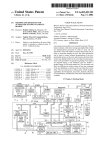
US006438212B1
(12) United States Patent
(10) Patent N0.:
(45) Date of Patent:
Lysaght et al.
(54)
(75)
AUTOMATED TELEPHONE LINE TEST
APPARATUS WITH INTELLIGENT
DIAGNOSTIC FUNCTION
OTHER PUBLICATIONS
CMC 7910DX DataStar 386 Generic Users Manual, Com
munications Mfg. Co., 1995.
Dynatel 745 Subscriber Loop Tester Product Pro?le, Min
nesota Mining and Manufacturing Co. (3M), 1996.
965 Subscriber Loop Analyzer (Speci?cations), 3M.
Inventors: Robert J. Lysaght, Glen Ridge, NJ
(US); Donald Finger, Peekskill, NY
(US); Je?'rey Hahn, Greenwich, CT
(US); Anthony M. Kolodzinski,
Massapequa Park, NY (US); Howard
Specialized Products Company (1988 Fall Catalog), pp. 128,
132, 133, 135.
“The Front, A Hand—Held Computer”, Telephony, Sep. 19,
Citron, South Salem, NY (US);
1988, pp. 24, 25.
“Test Equipment, The Old & The NeW”, Teleconnect, 9/89,
Yu-Ling Wu, Scarsdale, NY (US)
pp. 78—90.
(73) Assignee: Verizon Services Corp., Arlington, VA
(Us)
(*)
Notice:
US 6,438,212 B1
Aug. 20, 2002
“GTE’s NeW Line on Customer Service”, Datamation, May
1, 1990, pp. 68—70.
Model T136BSB Circuit Test Set, Wilcom (Plantronics),
Subject to any disclaimer, the term of this
patent is extended or adjusted under 35
5/84.
U.S.C. 154(b) by 0 days.
Primary Examiner—Duc Nguyen
Assistant Examiner—ReXford N Barnie
(21) Appl. No.: 08/933,485
Sep. 18, 1997
(22) Filed:
Int.
c1.7
...............................................
.. H04M 3/08
(51)
(52) US. Cl. ....................................................... .. 379/21
(58) Field Of Search ............................ .. 379/21, 22, 23,
(74) Attorney, Agent, or Firm—Rader, Fishman & Grauer
PLLC
(57)
A portable, automated telephone line test device includes a
test module which applies test signals to a telephone line to
379/24, 25, 26, 27, 29, 30, 5, 6, 1, 1-01,
be tested and detects electrical characteristics of the tele
12, 10-01, 22-02, 22-07, 27-01, 27-03, 27-04;
455/423; 364/528
(56)
phone line, and a user interface module. The user interface
module includes a microprocessor, a display, a keyboard and
a program memory in accordance With a standard micro
computer architecture. The processor of the user interface
Refel‘ellces Cited
U'S' PATENT DOCUMENTS
4,076,970 A
4,159,402 A
4,186,283 A :
ABSTRACT
module is programmed to control the test module to perform
a pre-programmed sequence of tests. The display provides
indications of the tests being performed. The programmed
2/1978 Lubarsky, Jr, et a1,
179/1752
R
6/1979 De GraauW et a1- -- 179/175-3 A
sequence is varied by the device according to test results.
Depending on the results obtained, the device also provides
1/1980 slmmonds ~~~~~~~~~~~~~~~~~ ~~ 379/21
interpretative diagnostic messages and instructs the user to
4,581,493 A
4/1986
Carry out additional test procedures
4,639,557 A
1/1987 Butler et a1. ................ .. 379/29
GaZZo et a1.
.....
. . . .. 379/21
(List continued on next page.)
12 Claims, 9 Drawing Sheets
14
28\
/
30
"F to Test
Module
Communications
‘
Interface
‘
;——
22
18
_
Program
Memory
Micro-Processor
i
r
A
.
Display
Y
26
Keyboard
>
\ 24
W or k'In
9
Memory
US 6,438,212 B1
Page 2
US. PATENT DOCUMENTS
5,208,846 A
5,241,277 A
4,670,898 A
6/1987 Pierce et a1. ................ .. 379/22
j?ggi?gig 2
$132; Burst“
4,788,708 A
“£1988
4’825’392 A
4/1989
4’837’811 A
4’843’62O A
4’92O’555 A
6/1989 Butler et
6/1989 Hagedom
4/199O lngalsbe
4,922,516 A
“990 Butler et a1‘
4 949 290 A
5,025,466 A
8/1990 Pike et al
6/1991 Hilligoss et a1‘
,
,
eta"
Freeman ' ' ' ' ' ' ' '
1/1992 Reum ~~~~~~~~~~~~ "
4/1992 Ackro? et al
’
. '
_ 379/6
379%
5,416,825 A
5/1995 Renger 61 a1. .............. .. 379/29
' ' "564/550
5,432,705 A
7/1995
379/96
379/21
379/21
5,440,610 A
5,442,679 A
5,511,108 A *
8/1995 Schillaci et a1. ..
8/1995 Regis et a1. .... ..
4/1996 Severt et a1. ..
379m
5,528,661 A
"
364/514
5,157,708 A
10/1992
379/21
5,170,114 A
5,195,124 A
12/1992 Lowenstein et a1.
.. 324/128
3/1993 Ishioka ...................... .. 379/27
*
Severt et a1.
. 364/481
379/24
379/34
379/21
.
6/1996 S111 6161. ..... ..
379/27
*
4/1997 Chang et a1. ..
5/1997 Hincis et a1. .... ..
379/21
379/6
5,754,624 A
5/1998 Sullivan et a1.
379/21
5,799,060 A *
8/1998 Kennedy et a1. ..
379/29
5,619,489 A
5,629,628 A *
5 825 174 A
..
. 324/538
4/1995 Kawaharata ................. .. 379/6
375/8
Gartwaite e161.
.......... ..
5,410,585 A
379/28
6/1992 szymborski et al.
Kefalas
23/921
364/580
379/1
.
5 081 670 A
5,121,342 A
8/1993
10/1994 Jung ___________ n
*
5’1O5’438 A
’
5 353 326 A
,
,
5/1993 Hammond et a1. ......... .. 379/15
*
*
5’96O’O6O A *
7
7
* cited by examiner
.
10/1998
Parker ...................... .. 374/106
9 1999 K .b 1
/
a‘ e
379 21
"""""""""""" "
/
U.S. Patent
Aug. 20, 2002
Sheet 1 0f 9
1°\
US 6,438,212 B1
14
12
/
“‘
User Interface
Module
Test Leads
Test Module $
16
Flg. 1
30
"F to Test
Module
Communications
Interface
22
1
#7‘
18
_
Program
M emory
‘
Micro-Processor
r
20
/
A
-
Dlsplay
Ke board
y
26
\24
Working
1‘
Memory
l
U.S. Patent
Aug. 20, 2002
( Diagnostic Function
\
US 6,438,212 B1
Sheet 2 0f 9
32
Selected
Perform Ground
34
l
Test
Perform Voltage
and Current Tests
58
Perform
Current
2-wire
Noise,
Loss,
Power Influence,
Balance and Stress
Tests
Test For Shortsl
Grounds / Detect
Q Levels
69
66
Confirm Line No.
4
Perform Kick and
Stress Tests
I etected ?
64
Locate Fault
68
Report Results
Fig. 3
End
U.S. Patent
Aug. 20, 2002
Sheet 3 0f 9
US 6,438,212 B1
/1 54
Perform Voltage
and Current Tests
156
158
Preform 2-wire
Loss and Circuit
Noise Tests
Functioning
Line?
160
Test For T-R Short
U.S. Patent
Aug. 20, 2002
Sheet 4 0f 9
Dial Up
US 6,438,212 B1
/102
Line l.D.
Facility
‘
110
Receive & Decode
Dual Tone Multi-Freq.
From 6.0.
y
/112
Retrieve Line
No. From
Memory
114
‘
Compare with
Line No. Data
From C.0.
Fig. 3B
104
Receive
Number l.D.
Request
106
Generate
Dual Tone Multi-Freq.
Corresponding To
Requesting Line
108
‘
Compare with
Line No. Data
From C.0.
Fig. 3C
1
‘
J
U.S. Patent
Aug. 20, 2002
US 6,438,212 B1
Sheet 5 0f 9
Loop Diagnostic Assistant
-Job ID
268L001
42,»
v0.6.0
rTicket Number
2079426298
"Test For
AC Volts
DC Volts
Current
Ground
TR
TC
2W_ireLoss
,NOISG
Power
44
“T 48
Balance
Stress
x 46
—Messages
.,52
‘I gtart
Up
_
onnect the GREEN lead to up and
BLACK lead to ground.
Leave the RED lead (ring) off until you
are instructed to connect it.
ENTER=START TESTING ESC=QU|T
F2=V|EW TEST RESULTS
Loop Diagnostic Assistant
-Ticket Number
268LD01
2079426298
"Test For
AC Volts
DC Volts
Current
Ground
ZWireLoss
,_ Noise
44
v0.6.0
—Job ID
TR
0.3V
TC
0.4v
-49.3v
+0.5!
+25.1mA
RC—
0.5v
-50.3v\_,~ 50
.
70dB Test Line
0.1dR 737-9963
19dB
Power
50118
Balance
61 dB
Stress
25dB
7“ 48
-— 46
—Messages
Stress test complete.
Net acceptable range: TR <30 dBrnc.
yr,’ 52
No imbalance exists between Tip & Ring.
: Test script complete:
Choose what you want to do next.
ENTER=RETEST LINE ESC=QUIT
F2=VIEW TEST RESULTS
U.S. Patent
Aug. 20, 2002
Sheet 6 0f 9
US 6,438,212 B1
Loop Diagnostic Assistant
-Job ID
v1.2.0
-Ticket Number
‘
TEST#000003 9147394606
*Test For
TR
TC
AC Volts
EC Voltts
urren
Ground
2WireLoss
0.3V
+
2é418.1X
.
m
0.4v
RC
0.6V
-0.3v -51.7v
.
70dB ANI Dlaled:
5.1dB Phone Number:
,, guise
ower
990
44 / Balance
Stress
22dB
-Messages
The Circuit ID from the switch
matches the subscriber’s phone number
on the trouble/service order ticket.
CID: 7394606
TN: 9147394606
ESC=STOP TESTING
08/22 01:36p
Fig. 5A
U.S. Patent
Aug. 20, 2002
US 6,438,212 B1
Sheet 7 0f 9
Trouble found:
Found unacceptable stress reading
Accepted range is <30 dBmc
one-sided fault (unbalance) exists.
Test script complete
Choose what you want to do next
ENTER=START TESTING ESC=QU|T
F2=V|EW TEST RESULTS
Fig. 6
Loop Diagnostic Assistant
-Job ID
268LD01
v1.2.0
-Ticket Number
2079426298
"Test For
TC
AC Volts
*DC Volts
\
44
0,4v
-0. v
a .
-0_5v
Stress
‘
“Fault/Distance
68
‘"
:
Coils:
48
W
AWG Ft:
OHMS: 100.00 EStFt:
T 46
Sect: 1
“\ 70
—Messages
Please enter the Temperature now:
Underground cable typically is 50°F.
I
Aerial cable is at outside
temperature unless extremely hot
(above 90°F). the add 10°F to
outside temperature reading.
ESC=END CALCULATOR
Ohms FAULT CALCULATOR
02/03 11:14a
Fig. 7
Temp: 68
Coils:
AWG: 26
AWG Ft:
OHMS: 100.00
EstFt:
N
Mixed(Y/N) :
1176 Sect:
Fig. 7A
N
U.S. Patent
Aug. 20, 2002
TIME
10:40AM
10:26AM
Sheet 8 0f 9
US 6,438,212 B1
JOB TICKET
268LD01
268LD01
"0hms” test(s)
>
>
TC = 3500.0kQ
RC = 3500.0KQ
TROUBLE FOUND:
Short circuit (Tip/Ring) appears to
be the problem.
Acceptable values are:
TR, TC & RC: > 2800 K9
Distance to fault calculations will be
done next:
Fault/Calculator:
Section = 1
Ohms = 100.00
V
Temperature = 68
LoadCoilsX = 0
AWGMixed = N
WireGaugeX = 26
OhmsFeet = 1176.00
Estimated distance to fault is 1176 feet
ESC=QU|T
UPIDOWN=SELECT
SCROLL:PANUP/PANDN=PAGE UID=L|NE
02/03 11 :32a
Fig. 8
Time
11 :00A
Job Ticket
N2DB2345
“Ground" Test(s)
Ground Test Complete
Found Good Ground.
Met Acceptable range: TR > 70dBmc.
“AC Voltage” Test(s)
Found AC voltage acceptable.
Acceptable values are:
ESC=QUIT
UPIDOWN=SELECT
jCROLUPANU PIPAN DN=PAGE UID=LINE
Fig. 9
U.S. Patent
Aug. 20, 2002
Sheet 9 0f 9
Time
11 :00A
Job Ticket
N2DB2345
10:40A
N2DB2345
US 6,438,212 B1
TR, T6 = R6 less than 5vAC
“DC Voltage" Test(s)
Found Little or no DC voltage.
ESC=QU|T
UPIDOWN=SELECT
SCROLL:PANUPIPANDN=PAGE UID=L|NE
Fig. 10
— TIME
JOB TICK_ET
10:40AM
268L001
10:26AM
268LD01
—-—---_
l
“Current Loop” Test(s)
>TR = +2822 ma
Loop current test completed
Met acceptable range TR = 23-65
“2W Loss” Test(s)
> “Test Line” 7-800-555-1212
Unable to get valid circuit loss reading
Acceptable range is TR < 8.5dB
Make sure the test line # is one.
which generates a 1004 Hz tone.
ESC=QU|T
UPIDOWN=SELECT
SCROLLIPANUPIPANDN=PAGE UID=LINE
02/03 11 :32a
Fig. 11
US 6,438,212 B1
1
2
AUTOMATED TELEPHONE LINE TEST
APPARATUS WITH INTELLIGENT
DIAGNOSTIC FUNCTION
test circuitry and for receiving test results from the test
circuitry, a program memory connected to the processor, and
a program stored in the program memory, the program
causing the processor to cause the test circuitry to perform
a ?rst one of the plurality of tests, and the program also
causing the processor to select a second test from the
FIELD OF THE INVENTION
This invention relates to portable apparatus for use in
plurality of tests on the basis of a result of a ?rst one of a
testing telephone lines from subscriber locations.
BACKGROUND OF THE INVENTION
10
It is knoWn to provide portable equipment to be used by
telephone company technicians in trouble-shooting tele
phone lines on Which trouble is reported. It is also knoWn to
use microcomputer technology, including a keypad
responsive processor and a processor-controlled display, to
15
aid the technician in using line-test equipment and as an
programmed to receive data from the test circuitry indicative
of a result of the test and, according to the result of the test,
An example of portable line-test equipment Which
employs microcomputer technology for input and output is
to control the display to display a message instructing a user
of the apparatus to perform a second test With respect to a
the CMC 7910DX DataStar 386 terminal and test module
(hereinafter “DataStar 386”), sold by Communications
25
reference.
It is an object of the invention to provide a portable
telephone line test device that is easier to use than prior art
devices.
It is a further object of the invention to provide a tele
phone line test device Which automatically carries out a
standardiZed sequence of tests.
It is still a further object of the invention to provide a
telephone line test device Which interprets results of tests
connected to the processor and a program memory con
processor further being programmed to receive data from the
test circuitry indicative of a result of the test and, according
to the result of the test, to control the display means to
display a string of alphabetic characters Which informs a
sources of line troubles on the basis of the test results.
user of the apparatus of the result of the test.
It is yet another object of the invention to provide a
telephone line test device Which displays interpretive mes
According to still a further aspect of the invention, there
is provided an automated telephone line test apparatus Which
includes test circuitry for applying test signals to a telephone
line to be tested and for detecting electrical characteristics of
sages and instructions to the user.
SUMMARY OF THE INVENTION
the telephone line, the test circuitry including a plurality of
test leads for being selectively connected to the telephone
45
and a program memory connected to the processor, the
play a message instructing a user of the apparatus to change
a connection betWeen the test lead and the telephone line to
be tested.
The test apparatus provided in accordance With the inven
tion carries out a complete and standardiZed trouble
test circuitry for controlling the test circuitry, a display
connected to the processor, and a program memory con
nected to the processor, the processor being programmed to
control the test circuitry so that the test circuitry performs a
pre-programmed sequence of tests, the pre-programmed
shooting operation Without relying on a high level of knoWl
edge on the part of the test technician. An effective and
55
also being programmed to control the display such that the
display provides a sequence of indications each correspond
consistent diagnostic procedure is programmed into the
apparatus. The test sequence is adapted according to the test
results and the likely source of trouble indicated by the test
ing to a respective test of the pre-programmed sequence of
results. The technician is guided step by step through the test
procedure and is provided With information that helps the
tests, each indication being displayed While the correspond
ing test is being performed.
technician to understand the process carried out by the
apparatus and the meaning of the test results. The technician
According to another aspect of the invention, there is
provided an automated telephone line test apparatus, includ
ing test circuitry for applying test signals to a telephone line
to be tested and for detecting electrical characteristics of the
forming a plurality of tests that are different from each other,
a processor connected to the test circuitry for controlling the
line, a processor connected to the test circuitry for control
ling the test circuitry, a display connected to the processor
processor being programmed to control the display to dis
teristics of the telephone line, a processor connected to the
telephone line, the test circuitry having capabilities of per
cable Which includes the telephone line to be tested.
According to still another aspect of the invention there is
provided an automated telephone line test apparatus Which
includes test circuitry for applying test signals to a telephone
line to be tested and for detecting electrical characteristics of
the telephone line to be tested, a processor connected to the
test circuitry for controlling the test circuitry, a display
nected to the processor, the processor being programmed to
control the test circuitry so that the test circuitry performs a
test With respect to the telephone line to be tested, the
performed by the device and automatically diagnoses
sequence of tests being performed in accordance With a
program stored in the program memory and the processor
processor, the processor being programmed to control the
respect to the telephone line; the processor further being
ment.
In accordance With the principles of the present invention,
objects noted above and other advantages are realiZed by
provision of an automated telephone line test apparatus
including test circuitry for applying test signals to a tele
phone line to be tested and for detecting electrical charac
processor and a program memory connected to the
test circuitry so that the test circuitry performs a test With
interface for outputting information from the line-test equip
Manufacturing Co., Los Angeles, California. The “Generic
User’s Manual” for the DataStar 386, published by Com
munications Manufacturing Co., is incorporated herein by
plurality of tests.
According to a further aspect of the invention, there is
provided an automated telephone line test apparatus Which
includes test circuitry for applying test signals to a telephone
line to be tested and for detecting electrical characteristics of
the telephone line, a processor connected to the test circuitry
for controlling the test circuitry, a display connected to the
receives comprehensive indications of the test results, and
recommendations for corrective action.
65
BRIEF DESCRIPTION OF THE DRAWINGS
The above and other features, advantages and aspects of
the present invention Will become more apparent upon
US 6,438,212 B1
3
4
reading the following detailed description in conjunction
line to be tested is satisfactorily grounded. Block 36 in FIG.
3 indicates that the test procedure branches depending on
Whether satisfactory grounding is found. If so, the apparatus
proceeds to perform basic tests to determine Whether basic
With the accompanying drawings in Which:
FIG. 1 is a high-level block diagram of a test apparatus
provided in accordance With the invention;
functions are available in the telephone line to be tested
FIG. 2 is a block diagram of a user interface module that
(block 54) Speci?cally, standard tests are performed for AC
is part of the apparatus of FIG. 1;
FIGS. 3, 3A, 3C are How charts Which illustrate a soft
Ware program for controlling a microprocessor that is part of
the user interface module of FIG. 2;
FIG. 3B illustrates operations at a central of?ce in con
nection With an automatic line identi?cation function; and
and DC voltage, and loop current. On the basis of these tests,
it is determined Whether basic line function is present on the
10
telephone line being tested (block 56). If so, a sequence of
transmission characteristic tests are performed (block 58). If
at block 56 basic line function Was not found, then the
procedure of FIG. 3 advances from block 56 to block 60, at
Which tests are performed to detect hard shorts or grounds.
FIGS. 4—11 illustrate various screen displays provided by
In a preferred embodiment, these tests include detecting
the user interface module of FIG. 2.
15
resistance levels among tip, ring and ground connections.
Block 62 of FIG. 3 indicates that the procedure branches,
DETAILED DESCRIPTION
according to Whether a hard short or ground is detected With
Apreferred embodiment of the invention is implemented
respect to the tip and ring connections. If so, the location of
the fault is determined (block 64). OtherWise, tests are
as a softWare enhancement of a conventional device, such as
the above-referenced DataStar 386 device. An overvieW of
a suitable hardWare environment for implementation of the
invention is provided by FIGS. 1 and 2. In FIG. 1, a test
device 10 in accordance With the operation is shoWn to
performed to gather more information about a “soft” fault or
open circuit condition (block 66) Preferably these tests
include a capacitive “kick” test and a stress test. In all cases,
as indicated by block 68, results of the various tests are
indicated on the display 26.
include a test module 12 and a user interface module 14. The
test module 12 has test leads 16 suitable for connection to
tip, ring and ground sides of the telephone line to be tested.
25
The test module and user interface module may respectively
correspond to the test module and terminal portions of the
DataStar 386 device. It is also contemplated to integrate the
test module and user interface module into a single unit.
FIG. 2 illustrates salient components of the user interface
Referring again to block 36, a ?nding of “bad ground” at
that point leads the apparatus 10 to give the user the
opportunity to reattach the ground lead to the telephone
cable and to retest for adequate ground (block 38). If the user
elects to do so, the procedure loops back to blocks 34 and 36.
OtherWise, the procedure branches to a curtailed test
sequence (FIG. 3A) in Which the apparatus only performs
module 14, Which preferably is arranged in accordance With
tests that can provide meaningful results in the absence of
a standard architecture for a microcomputer. Included in the
module 14 are a microprocessor 18, a Working memory 20
satisfactory grounding. In this case, as indicated by block
associated With the microprocessor 18, a program memory
22 Which stores a program for controlling operation of the
microprocessor 18, a keyboard 24 by Which a user provides
35
154 of FIG. 3A, the same voltage and current tests are
performed as Were mentioned above in connection With
block 54. Then, the procedure branches (block 156) accord
ing to Whether basic line function is found. If so, block 158
folloWs, in Which the tWo-Wire loss and circuit noise tests are
performed. PoWer in?uence, balance and stress tests are
input to the microprocessor 18, and a display 26 by Which
the microprocessor provides output to the user. Also
included in the module 14 are an interface 28 through Which
omitted, since valid results cannot be obtained Without good
the microprocessor 18 eXchanges signals With the test mod
ground. If at block 156 basic line function Was not found, a
ule 12, and a communications interface 30 through Which
the microprocessor 18 can exchange data With a remote
After either of blocks 156 and 158, the test results are
test for a tip-ring short circuit is performed (block 160).
device such as a host computer.
Operation of the apparatus 10 to perform telephone line
trouble-shooting Will noW be discussed, initially With refer
reported to the user (block 68, FIG. 3).
45
ence to FIG. 3. FIG. 3 illustrates in ?oW-chart form a
program stored in the program memory 22 Which causes the
apparatus to carry out an adaptive diagnostic test sequence.
The diagnostic function illustrated in FIG. 3 may be selected
by the user from a main menu (not shoWn) displayed on the
display 26. Selection of the process of FIG. 3 from the menu
is indicated at initial step 32 of FIG. 3. In response to
selection of the diagnostic function, a screen display like that
shoWn in FIG. 4 is provided by the display 26. The screen
Referring once more to FIG. 3, after the sequence of tests
represented by block 58 are performed, the apparatus carries
out a procedure to con?rm, by machine-to-machine contact,
that the telephone line that has just been tested matches the
line indicated by the job assignment. This line con?rmation
process is represented by block 69 in FIG. 3, and Will noW
be described With reference to FIGS. 3B and 3C.
55
display of FIG. 4 includes a number of ?elds, including job
Referring initially to FIG. 3B, the test apparatus requests
identi?cation of the telephone line under test by dialing up
a line identi?cation facility provided in the central office
(block 102.). That is, the test apparatus couples onto the
telephone line under test pre-determined dialing signals
Which correspond to the telephone number (dialing no.) of
ID ?elds indicated at 42, a ?eld 44 Which lists speci?c tests
that may be carried out by the apparatus, and test result data
?elds 46, 48 and 50. Included at a bottom part of the display
of FIG. 4 is a message ?eld 52. Upon initialiZation of the
the central office line i.d. facility. These dialing signals are
received at the central of?ce, Which treats the dialing signals
as a request to identify the telephone line on Which the
diagnostic function, the message in the message ?eld 52
instructs the user to connect some of the test leads 16 to
dialing signals are received (block 104 FIG. 3C). The central
of?ce then generates DTMF (dual tone multi-frequency)
appropriate sides of the telephone line to be tested. The user
can then initiate the diagnostic procedure.
At the beginning of the diagnostic procedure, as indicated
number) of the telephone line on Which the request Was
at block 34 in FIG. 3, the test apparatus performs a test to
determine Whether the cable Which contains the telephone
signals Which represent the telephone number (dialing
65
received (block 106). The central of?ce couples the DTMF
signals to the requesting telephone line for transmission to
the test apparatus (block 108).
US 6,438,212 B1
5
6
Referring again to FIG. 3B, the apparatus receives the
DTMF signals transmitted from the central of?ce (block
110), and decodes the DTMF signals to produce data Which
indicates the telephone number corresponding to the tele
sequence of tests. Speci?cally, When the AC voltage tests is
being performed, the “>” may be positioned adjacent the
Words “AC Volts” in ?eld 44. When that test is complete, the
indicator “>” Would be moved doWnWard so as to be
adjacent to the Words “DC Volts”. The indicator “>” Would
phone line under test. There folloWs block 112, at Which the
be positioned adjacent the corresponding Words in FIG. 44
apparatus retrieves from memory 20 (FIG. 3) data Which
identi?es the telephone number of the telephone line Which
is the intended subject of the Work assignment (e.g., the
as each test in the sequence is performed, concluding With
telephone line on Which trouble Was reported). It Will be
understood that the Work assignment data, including the
10
number of the line to be tested, had previously been stored
before commencing the test procedure. The apparatus then
compares the telephone number data retrieved from memory
With the telephone number data obtained by decoding the
DTMF signals from the central office, to con?rm that the line
15
actually tested Was the one intended to be tested according
to the Work assignment.
This machine-to-machine Work assignment con?rmation
procedure represents an advance over prior art practice, in
the Word “Stress” as the stress test Was being performed at
the end of the transmission characteristic tests of FIG. 58. In
addition, as results Were obtained for each of the tests, the
?elds 46, 48 and 50 Would be populated With corresponding
test data obtained by carrying out the respective test. In
addition, the progress through the sequence of tests is
re?ected by verbal messages provided in the message ?eld
52. For example, When the AC voltage test has been com
pleted and the DC voltage is being carried out, a message
such as the folloWing may be displayed in the message ?eld
52:
“AC Voltage tests complete. Met acceptable values: TR,
TG & RG<5 vAC.”
response, generated via speech synthesis by the central office
In addition, the folloWing text may also be displayed:
“DC voltage test noW being performed.”
FolloWing is a sequence of messages displayed in the
equipment, Which stated the line number of the tested line.
message ?eld 52 as the sequence of tests proceeds through
Which the test technician dialed up the central of?ce tele
phone line i.d. facility, and then listened to an audible verbal
The prior practice required the technician to match the
number given by the machine-generated speech With the
steps 54 and 58, and satisfactory results are found through
25 out.
Work assignment data specifying the line intended to be
tested. The machine-to-machine con?rmation procedure of
Initially, after the ground test has been performed, the
message displayed is:
“Ground test complete. Found good ground. Met accept
able range: TR<70 dBrnC. Connect the ring lead (red)
FIGS. 3B and 3C relieves the technician of the effort of
carrying out line i.d. con?rmation, While enabling the test
apparatus to automatically store data con?rming that the line
before continuing.”
tested Was in fact the line Which Was the intended subject of
Then, When the ring lead has been connected, the appa
the test assignment.
Further details of the program illustrated in FIG. 3 Will be
understood from the pseudo-code listing annexed hereto as
Appendix I, and from the script ?le printouts annexed hereto
ratus performs the AC voltage test and on completing the test
35
as Appendix II. In addition, the folloWing discussion Will
the following message is displayed:
“AC voltage tests complete. Met acceptable values: TR,
Then the DC voltage test Would be performed, and upon
highlight aspects of the adaptive nature of the diagnostic
functions of the test apparatus 10, and particularly the
completion the folloWing message displayed:
“DC voltage tests completed. Met acceptable values: TR
guidance and information provided to the user by the
apparatus.
TEST SEQUENCE EXAMPLE—NO TROUBLE
FOUND
Initially, it Will be assumed that the telephone line to be
tested is operating in accordance With prescribed speci?ca
45
tions in all respects. This may occur, for example, if there is
an error in reporting trouble on the line, or if the line is being
Since the voltage, current and ground tests all indicated
acceptable readings, the tWo-Wire circuit loss test is per
formed next. Upon completion of the test With acceptable
and repair operation that has already been performed With
respect to the telephone line. In any case, once the diagnostic
function has been started, the ground, AC voltage, DC
readings, the folloWing message is displayed.
voltage and loop current tests are performed as called for by
block 54 in FIG. 3. According to the present assumption, all
of those tests indicate proper functioning of the telephone
“Circuit loss test completed. Met acceptable range:
55
ing a tWo-Wire circuit loss test, a circuit noise test, a poWer
in?uence test, a longitudinal balance test, and a stress test.
It is to be understood that each of these individual test
procedures is a standard test Which is Well knoWn to those
TR<=20 dBrnC.”
Then the poWer in?uence test Would be performed, and
upon completion the folloWing message displayed:
“PoWer in?uence test completed. Met acceptable range:
of ordinary skill in the art, and therefore need not be
described in detail. As the sequence of tests represented by
TR<90 dBrnC.”
The next test to be performed is the longitudinal balance
blocks 54 and 58 is being performed, the apparatus provides
test. Upon completion of that test, the folloWing message is
to the user indications of What the apparatus is doing at any
indication mark such as “>” in the test sequence ?eld 44 to
indicate that the apparatus is progressing through the
The next test is the circuit noise test. Upon satisfactory
completion of this test the folloWing message is displayed.
“Circuit noise test completed. Met acceptable range:
mission characteristic tests represented by block 58, includ
given time. For example, the apparatus may display an
the loop current test, the folloWing message is displayed:
“Loop current test completed. Met acceptable range:
TR=23—65 mA.”
tested to con?rm successful completion of a trouble shooting
line, so that the apparatus proceeds to a sequence of trans
As the above tests are completed, in addition to displaying
the messages indicated above, the ?elds 46, 48 and 50 are
populated in the appropriate roWs With data corresponding to
the actual test results.
The sequence of tests continues, and after completion of
65
displayed:
“Longitudinal balance completed. Met acceptable range:
US 6,438,212 B1
7
8
The ?nal test in the sequence is the stress test. Upon
completion of this test, the screen display of FIG. 5 Would
message, “Check for breaks in ground conduit.” Also, if the
stress test carried out by the apparatus provides a marginal
be provided. In the message ?eld 52, completion of the test
reading, the apparatus displays the message:
“One-sided fault (imbalance) may be forming. Check a
good pair to see if stress reading is typical for this
is indicated as Well as ?nding of acceptable results. It Will be
noted that the ?elds 46, 48 and 50 have been fully populated
area—marginal outside plant.”
With data indicating the results of the tests that have been
performed. It Will also be noted that, at the bottom of the
message ?eld 52, the user is advised that the test sequence
has been completed and the user’s options are presented.
FIG. 5A is a screen Which indicates that the apparatus has
As another example, if the “kick” test performed as part
of block 66 (FIG. 3) indicates a tWo-sided open condition,
the user is instructed:
10
performed the automatic line number con?rmation proce
dure described above in connection With FIGS. 3B and 3C.
condition. The stress test Will be done next, to test for
electrical balance.”
It has been noted above that, during the course of the test
EXAMPLES WITH TROUBLE FOUND
If during the sequence of tests an unacceptable reading is
found, a corresponding message is provided in the message
?eld 52. An example of such a message is shoWn in FIG. 6,
Which shoWs the message provided When the stress test
results in an unacceptable reading. Other messages indica
tive of unacceptable conditions are listed in Appendix II.
As has been discussed above, if basic line function is not
found at steps 54 and 56 (FIG. 3), testing for a hard fault
takes place. FIG. 7 illustrates a screen display provided
“Check a good pair to verify kick values indicate an open
sequence carried out by the apparatus, the apparatus
15
instructs the user to change the con?guration of the connec
tion betWeen the test leads and the line being tested. For
example, after detection of adequate ground, the user is
instructed to connect the ring lead to the ring side of the line.
HoWever, according to another embodiment of the
invention, the user may be instructed to connect all three test
leads respectively to tip, ring and ground at the beginning of
the test sequence. This embodiment is further provided With
suitable relays or other sWitches in the test module that are
controlled to effectively control connection or disconnection
When a hard fault is found. The tests for Which unacceptable 25 of the lead Within the test module.
readings Were obtained are marked With an asterisk in ?eld
It should also be noted that, in a preferred embodiment of
44 (in this example the “DC Volts” and “Ohms” test entries
are so marked) and entries in ?elds 46, 48 and 50 indicative
of readings outside of the acceptable range are highlighted.
the invention, the apparatus displays a reminder to the user
that When a neW line is to be tested, the test leads must be
disconnected from the previous line and connected to the
(In this example, the highlighted out-of-range data are the
neW line.
entries in ?eld 46 (tip-ring) corresponding to the DC volts
and Ohms tests, and the entry in ?eld 50 (ring-ground)
corresponding to the DC volts test.)
If a hard fault is found, an additional ?eld 70 collects the
data required to calculate the distance to the fault. Amessage
in ?eld 52 prompts the user to enter the required data. The
“coils” entry is for indicating Whether load coils are present
on the cable. A pop-up list (not shoWn) prompts the user to
35
trouble on the basis of test results. The apparatus also keeps
the technician informed as the test sequence proceeds, test
results are obtained, and diagnostic conclusions reached.
enter the number of load coils. Entries for the Wire gauge are
also provided. Based on the entered data, an estimated
distance to the fault is calculated and displayed, as shoWn in
FIG. 7A. The user also has the option to change some of the
The technician is provided With step-by-step guidance as to
actions needed to continue the test procedure and With
recommendations for remedial actions. The apparatus is
programmed to provide consistent and effective trouble
shooting procedures Which make ef?cient use of the tech
parameters and have the distance calculation repeated.
When the test sequence is complete, the user is permitted
to direct the apparatus to retest the line. Alternatively, the
nician’s time and minimiZe callbacks on trouble reports.
45
user may vieW the test results obtained, or may exit from the
FIG. 8 shoWs an example of a screen display provided
When the user elects to vieW test results. In this case, it is
assumed that a hard fault (tip-ring short) has been found and
of previously determined test results in Which acceptable
computer from the portable line-test apparatus. The
uploaded data may include a list of the tests for Which
satisfactory and unsatisfactory results Were founded, as Well
as the actual test data Where the results Were unsatisfactory.
55
results are shoWn. The screen display of FIG. 10 may be
reached by scrolling doWn from the display of FIG. 9. In the
example shoWn in FIG. 10, a lack of DC voltage is indicated.
FIG. 11 is another example of a screen vieWable through
the “vieW test results” option. In this case, the tWo-Wire
circuit loss test resulted in an unacceptable reading.
Another notable feature of the present invention resides in
instructions provided by the apparatus to the user to engage
in additional tests in certain circumstances.
For example, if the ground test carried out by the appa
ratus fails to ?nd good ground, the apparatus displays the
Also, in accordance With conventional practice, the por
table line-test apparatus may be connected by telephone line
With a central administrative computer, so that job assign
ment data may be doWnloaded to the apparatus from the
central computer. In addition, test result data and other
reports on jobs performed can be uploaded to the central
automated diagnostic function.
the estimated distance to fault calculated.
FIGS. 9, 10 and 11 are other examples of screen displays
provided in response to the selection of the “vieW test
results” function. FIG. 9 illustrates an initial screen display
The portable telephone line testing apparatus disclosed
herein provides signi?cant advantages in terms of aiding
telephone technicians in the performance of line trouble
shooting operations. The apparatus provides automated
selection and sequencing of test procedures and diagnosis of
Also, the data uploaded by the apparatus may include a
con?rmation that the line number provided by the central
of?ce during the procedure of FIGS. 3B and 3C matched the
number of the line speci?ed in the Work assignment. If there
Was not a match, the number of the line actually tested may
be reported.
In all cases it is understood that the above-described
arrangements are merely illustrative of the many possible
speci?c embodiments Which represent applications of the
65
present invention. Numerous and varied other arrangements
can be readily devised in accordance With the principles of
the present invention Without departing from the spirit and
scope of the invention.
US 6,438,212 B1
9
10
What is claimed is:
tests has one or more of a voltage test and a loop current test
1. An automated telephone line test apparatus, compris
on said line to be tested to determine if said line to be tested
ing:
test circuit means for applying test signals to a telephone
line to be tested, and for detecting electrical character
istics of said telephone line to be tested;
is functioning, and if said line to be tested is determined to
be functioning, said branch of subsequent tests further has a
5 tWo-Wire circuit loss test and a circuit noise test circuit, and
one or more of a poWer in?uence test, a longitudinal balance
test and stress test on said line to be tested; and When said
a processor connected to said test circuit means for
ground test indicates a failure to ?nd a good ground, said
controlling said test circuit means;
display means connected to said processor; and
a program memory connected to said processor; said
10
processor being programmed:
to control said test circuit means such that said test
circuit means performs a pre-programmed sequence
of a plurality of different tests With respect to said
telephone line to be tested, said pre-programmed
sequence of a plurality of different tests being per
formed in accordance With a program stored in said
program memory;
to control said display means such that said display
means provides at the start of said performance of
said pre-programmed sequence of tests a display
having a ?rst ?eld in Which alphabetic information
identifying each of said plurality of different tests is
together listed and a second adjacent ?eld in Which
the results of said tests are to be displayed and as
if said line to be tested is functioning, and if said line to be
tested is determined to be functioning, said branch of
subsequent tests further has a tWo-Wire circuit loss test and
a circuit noise test on said line to be tested.
6. An apparatus according to claim 4, Wherein said test
15
being performed is one or more of a voltage test and a loop
current test on said line to be tested, and: if said test being
performed indicates a functioning line, said branch of sub
sequent tests has a tWo-Wire circuit loss test and a circuit
noise test and one or more of a poWer in?uence test, a
longitudinal balance test and stress test on said line to be
tested; and if said test being performed indicates a non
functioning line, said branch of subsequent tests has an ohms
test on said line to be tested to determine a fault on the line
to be tested, and if a fault is not determined on the line to be
25 tested, said branch of subsequent tests has one or more of a
capacitive kick test and a stress test on the line to be tested.
testing proceeds to further control said display means
to provide for each test: in said ?rst ?eld adjacent the
7. An apparatus in accordance With claim 4, Wherein said
test being performed is an ohms test on the line to be tested
to determine a fault on the line to be tested, and if said test
being performed indicates: a fault has not been detected on
the line to be tested said branch of subsequent tests has one
listing of the corresponding test and during the
performance of the test a display of an indication that
the test is being performed; and in said second ?eld
a display of the numeric readings of the results of the
or more of a capacitive kick test and a stress test on the line
test.
to be tested.
2. An apparatus according to claim 1, in Which said
plurality of different tests Which are listed in said ?rst ?eld
include at least an AC voltage test, a DC voltage test, a loop
branch of subsequent tests has one or more of a voltage test
and a loop current test on said line to be tested to determine
8. An automated telephone line test apparatus, compris
35
ing:
test circuit means for applying test signals to a telephone
current test, a ground test and a tWo Wire current loss test.
line to be tested, and for detecting electrical character
istics of said telephone line to be tested;
3. An apparatus according to claim 2, in Which said
plurality of different tests Which are listed in said ?rst ?eld
further includes a circuit noise test, a poWer in?uence test,
a longitudinal balance test and a stress test.
a processor connected to said test circuit means for
40
4. An automated telephone line test apparatus, compris
ing:
controlling said test circuit means;
display means connected to said processor; and
a program memory connected to said processor;
test circuit means for applying test signals to a telephone
line to be tested and to a cable containing the telephone 45
said processor being programmed:
to control said test circuit means so that said test circuit
means performs a test With respect to said telephone
line to be tested;
to receive data from said test circuit means indicative of
a result of said test; and
according to said result of said test, to control said
display means to display a message instructing a user
of the apparatus to perform a second test With respect
to a cable Which includes said telephone line to be
tested.
line to be tested, and for detecting electrical character
istics of said telephone line to be tested and said cable,
said test circuit means having capabilities for perform
ing a plurality of tests that are different from each other;
a processor connected to said test circuit means for 50
controlling said test circuit means, and for receiving
test results from said test circuit means;
a program memory connected to said processor; and
a program stored in said program memory, said program
for controlling said processor to cause said test circuit 55
means to selectively perform said plurality of tests; and
said program being adapted to cause for each of one or
more of said plurality of tests being performed on the
basis of a result of the test being performed said
9. An automated telephone line test apparatus, compris
ing:
test circuit means for applying test signals to a telephone
line to be tested, and for detecting electrical character
istics of said telephone line to be tested;
a processor connected to said test circuit means for
processor to only branch from the test being performed
to subsequent tests of said plurality of tests Which Will
provide meaningful test results, said test circuit means
branching to said subsequent tests responsive to said
controlling said test circuit means;
display means connected to said processor; and
processor.
said processor being programmed:
5. An apparatus according to claim 4, Wherein said test
being performed is a ground test on said cable and When:
said test indicates a good ground, said branch of subsequent
a program memory connected to said processor;
to control said test circuit means such that said test
circuit means performs a test With respect to said
telephone line to be tested,
US 6,438,212 B1
11
12
to receive data from said test circuit means indicative of
a result of said test; and
operating the test module to carry out a sequence of tests
With respect to said telephone line in response to said
stored program, said sequence of tests automatically
branching on the basis of respective results of said
according to said result of said test to control said
display means to display a message instructing a user
of the apparatus to perform a second test With respect
to a cable Which includes said telephone line, said
second test being a test With respect to a Wire pair
other than a Wire pair corresponding to said tele
phone line to be tested.
tests;
displaying a message instructing a user of the testing
device to perform a test With respect to a cable Which
contains said telephone line to Which said test module
10. An automated telephone line test apparatus, compris
is connected; and
ing:
test circuit means for applying test signals to a telephone
line to be tested, and for detecting electrical character
istics of said telephone line to be tested;
a processor connected to said test circuit means for
controlling said test circuit means;
15
display means connected to said processor; and a program
memory connected to said processor; said processor
performing said test With respect to the cable.
12. A method of testing a telephone line utiliZing a
portable test device, said test device including a test module
connected to said telephone line, a microprocessor for
controlling the test module, and a memory storing a program
for controlling the microprocessor, the method comprising
the steps of:
being programmed:
to control said test circuit means so that said test circuit
operating the test module to carry out a sequence of tests
means performs a test With respect to said telephone
line to be tested;
to receive data from said test circuit means indicative of
a result of said test; and
according to said result of said test, to control said
With respect to said telephone line in response to said
stored program, said sequence of tests automatically
branching on the basis of respective results of said
tests; and
displaying a message instructing a user of the testing
display means to display a string of alphabetic char
25
acters Which informs a user of the apparatus of said
device to perform a test With respect to a cable Which
result of said test, said string of alphabetic characters
contains said telephone line to Which said test module
including a verbal message stating to the user that the
test result is one of Within a range of acceptable
values and not Within a range of acceptable values.
11. A method of testing a telephone line utiliZing a
portable test device, said test device including a test module
connected to said telephone line, a microprocessor for
controlling the test module, and a memory storing a program
for controlling the microprocessor, the method comprising
the steps of:
is connected;
performing said test With respect to said cable; and
prior to said performing step, connecting said test module
to a Wire pair contained in said cable, said Wire pair
being different from a Wire pair corresponding to said
telephone line.