1
US006453435B1
(12) United States Patent
US 6,453,435 B1
Sep. 17, 2002
(10) Patent N0.:
(45) Date of Patent:
Limon, Jr. et al.
(54) METHOD AND APPARATUS FOR
OTHER PUBLICATIONS
AUTOMATED TESTING OF CIRCUIT
BOARDS
Measure Serial Control User Manual, National Instruments
Corporation, Aug. 1996.*
TestStand User
Manual, National Instruments Corporation,
*
(75) Inventors: Rogelio Limon, J r., Mesquite, TX
(US); John T. Riley, Allen, TX (US);
1366- 1998
Robert A. Beasley, Dallas,
* Cited
examiner
(73) Assignee: Fujitsu Network Communications,
Inc” Richardson, TX (Us)
P''ima"y Examiner—A1bert Decady
Assistant Examiner—Joseph D. Torres
( * ) Notice:
(57)
74 Attorney, A g em, or Firm—Baker Botts L.L.P.
Subject' to any disclaimer, the term of this
ABSTRACT
patent ls extended or adJusted under 35
USC. 154(b) by 0 days.
Atest station is provided to test a circuit board unit. The test
station includes a disk drive storing uncompiled ?les Which
are interpretatively processed in order to carry out test
(21) App1_ No; 09/222,541
_
operations. Abar code reader can scan a label on the unit, in
(22) Flled:
Dec- 29’ 1998
order to accurately identify the unit. The label information
(51)
Int. Cl.7 .............................................. .. G01R 31/28
can be used to ensure accurate programming of any pro'
(52)
58
U S C]
F: I'd
(
)
1e
"""
0
""""""""""""""""""
714/724
H24 745
grammable devices on the unit, and accurate selection of the
correct test de?nition ?les for the unit. Step-by-step instruc
"""""""""""""""" "
’
tions can be provided to an operator regarding every manual
earc
(56)
References Cited
act required during a test de?nition, and can include a
graphic image of each such manual act. The test station can
have tWo different test modes, Where at least one command
U.S. PATENT DOCUMENTS
4 718 064 A *
714 28
of the test de?nition is carried out for one mode but not the
4’76O’33O A * 7;1988 Leia}: et a‘ """""" " 71432
other. The test station has a debug mode, Which includes
4’901’221 A
1 1988 Ed
*
d
1
2/1990 Kodesk'y'e'ee'l' ' ' ' '
' ' ' "345/348
capabilities for breakpoints, step mode, dynamic alteration
703/25
of test de?nitions, and dynamic observation and alteration of
5,045,994 A * 9/1991 Belfer et aL
5,432,705 A
5,511,108 A
*
*
7/1995 Severt et a1. ..
4/1996 Severt et al. ..
5,974,257 A
* 10/1999 Austin ......................... .. 717/8
SERVER
. 702/120
379/21
T7
Variables
27 Claims, 9 Drawing Sheets
r ———————————————————————————————————— — —: — -|
27
DISPLAY
"
HARD DISK DRIVE
DATABASE ElLE
NEW“ H
II
PRINTER H 21
H 22: INTERZACE
\e28
MAC ADDRESS FILE
15
23
\_
|—
—
—
':
—
—
—
—
—
—
—
—
—
<
l
|
—
—
—
78
LSTATIONJI
LSTATIONJ:
'''
'"- |
ETHERNET
PORT
—
—
—
—
—
\GPIB
—
-—
—
86 ii
/
76
/
/
PARALLEL
SERML
PORT
PORT
(RS232)
79
83
\
METER
:
INSTRUMENT
_ _ _ _ _ _
101 Vw
|
l
I
i
I Vcc
T '| r
'_——i—>
NN
T R
CONNECTOR
‘I
l I}CODE {I
I ' LLA_BEL_I I
l
1
N37
4}
UUT
FEE _ i2 1.13
l_ ::::_-::::
—————————————— — —
111
'
- - - - - - - - - - - - — - - - 2>'
LATTlcE
1131/ DEVICE
BAR
72
/36
@f
OPTICAL
I 1 1
5 \ i if BAR-I:
68 i
UUT CONNECTOR
_ _ _ _ _ _ _ _ _ _ _ _ _ _|
/
-
l
_____|
| ETHERNET PORT ||HEA0ERJ<}-_—_—-|
'\
,- _ _ i. _ _ _l
.
_ ___
OPHCAL <1? m 4}
CONNECTOR
II
6? I: SERRA
BADGE
102 UN
l'
REAPER
I
I/O CA
BIDIRECTIONAL
64/ DRIVERS
T T R
10
/
POWER
103,\/\
:
<: BAR CODE :
DIGITAL
SUPPLY
F _ _ _ _ _ _ _ _ _ _ _ _ _ _
|
47\
67
63/__PAR_AL_LE_L__
77
OPTICAL
:
:- _ _ _
(FIG. 2)
SERIAL
Q T0
82
CODE
LABEL
1
l
3% :
{I
: GENERATOR
PATTERN !llé‘éi?‘a
I
<%_|
—'
GPIB/
T
l
KEYBOARD
K
\
I INTERFACE
—
l _____\ _ _ _ _ __
|
OPTICAL T
I
l
HAR
I’ TEST ‘if TEST ‘IT 81
TEST STATION
—
FEB
43
‘a
-51
_V-/ _V! :
/
1b+
41/
WORKSTATION
I NETWORK
NETWORK II
ARCHIVE ETLE
LOG FlLE
'l
H
42
:
ll
FLASH
*/
MEMORY
4,112
l
_ _ _ _ _ _ _ _ _ _ _ ___J
x1 3
U.S. Patent
Sep. 17, 2002
Sheet 2 0f 9
US 6,453,435 B1
HOSTSOFT
HOSTSOFT.EXE
BMP FILES
LAT
FTP
DLL
LIB
FIG- 2
f1 33
,/
FILES
FILES
FILES
FILES
PROGRAMS
MACROS
PRGDEVS
TABLES
LOGFILES
PRG FILES
MAC FILES
BINARY FILES
DATABASE FILE
LOG FILES
/
136
X
X
137
\
138
139
291
FIG. 9
/
292
Global Variables
\
140
[EIEItXI
RSBEQERQQSEL
1
__________________ __‘__'I_I"_I*Q_‘__I_F_Q~_‘_1I_L
Int
704 ____________________
PW2
Int
70s
OptMeter
Int
703
Attenuator
ClkSwitch
FreqCounter
Int
Int
Int
706
71 1
713
téluiiééijiiériYéiiéi?ééi
Y
,393
igsdmptéaqgéfffj“Ti‘j‘ 1‘ 111111‘?“Ift‘1111135111111“(15; ;|IrjjIjI1j;;jfI;ji gdjgliijjgjg‘“*****“*"1‘"
PW1
PW2
Int
Int
“““““ “If A
704
705
OptMeter
Int
703
Attenuator
ClkSwitch
FreqCounter
Int
Int
Int
706
71 1
713
v
U.S. Patent
Sep. 17, 2002
US 6,453,435 B1
Sheet 4 0f 9
P1
TURN OFF "PASS"
———l
TURN ON "TEST BUSY". [212
SEARCH HOSTRUN.IN|
214
/
-
201\ REQUEST PASSWORD
PROMPT USER FOR
NO
REVISION NUMBER.
AND ST0RE TT
202
<_—____l
V
PASSWORD
CORRECT?
RPRlggg @{PE RUN I217
l
l
I______Y______‘I
PROCESS PRC AND |
|
:
MAC FILES IN
‘V221
T. lNIEBERETDIE M0135 ..
PROMPT USER T0
206/ SCAN UUT BAR CODE
2/42
NO
SAvE TEST RESULTS
To LOG FILE
<—__|
V
TURN OFF "TEST BUSY" I243
PROMPT USER To
208/ PUT UUT IN SOCKET
247
_
NO
/
TURN ON "PASS"
<—l
@248
FIG. 4
U.S. Patent
Sep. 17, 2002
Sheet 8 0f 9
US 6,453,435 B1
261
257 258
259 FIG 8
'/ 290
l
@mm
int val=0
Value-1
278-”
goto endofmacro
:veryEnd
Pass I'this is the very end of the macro"
it Value==
goto nexttest
endit
~/ :timetoquit
return Value
:endofmacro
Pass "this is the end of the macro"
if val==
goto veryEnd
FIG.
=
Evaluate Variable
Variable Name: OptMeter
Type:
lni
70
CIX
US 6,453,435 B1
1
2
METHOD AND APPARATUS FOR
AUTOMATED TESTING OF CIRCUIT
BOARDS
test production boards Will typically not be given such
training. Consequently, they Will simply run the speci?ed
test de?nitions Without fully understanding What the tests are
doing.
STATEMENT REGARDING COPYRIGHT
RIGHTS
A portion of this patent disclosure is material Which is
subject to copyright protection. The copyright oWner has no
objection to the facsimile reproduction by anyone of the
patent document or the patent disclosure, as it appears in the
Patent and Trademark Of?ce patent ?le or records, but
Another consideration is that it is dif?cult to train an
operator to accurately conduct tests on a variety of different
types of units, because it becomes more and more difficult
for the operator to remember each of the various sequences
of manual steps Which must be carried out for each of the
10
otherWise reserves all copyright rights Whatsoever.
TECHNICAL FIELD OF THE INVENTION
is possible for an operator to inadvertently select the Wrong
test de?nition for use in testing a given circuit board. In a
15 situation Where a circuit board .has a programmable part
This invention relates generally to testing of units such as
electronic circuit boards and, more particularly, to comput
eriZed systems for automated testing of such units.
Which must be programmed, it is possible for an operator to
inadvertently select the Wrong information for use in pro
gramming the programmable part. There is also a need to be
able to easily sWitch betWeen a normal level of testing and
a more rigorous level of testing, Without necessarily requir
ing the operator to select one of tWo different test de?nitions,
and Without requiring a test developer to develop tWo
entirely separate test de?nitions for the same unit.
BACKGROUND OF THE INVENTION
Over the years, as integrated circuits have become pro
gressively more complex and sophisticated, electronic cir
cuit boards Which use these integrated circuits have also
become progressively more complex and sophisticated.
Consequently, in order to accurately test these electronic
circuit boards, more and more sophisticated techniques have
been required. In particular, circuit board manufacturers
have decreased the use of manual testing techniques in favor
25
minimal training, Which has features facilitating debug and
dynamic alteration of test de?nitions, Which can provide an
operator With step-by-step instructions for manual acts
Which are stored by the test system and Which are then
automatically carried out in order to effect testing.
A traditional approach has been to prepare a custom
35
entirely satisfactory in all respects. For example, in order to
pro?cient in a sophisticated computer programming lan
Which automates the selection of information that is to be
programmed into a programmable part on a unit under test.
According to one form of the present invention, a tech
nique is provided to address this need, and involves a test
to a unit to be tested; a memory portion Which stores a
program and a test ?le, the test ?le containing a test
de?nition Which speci?es at least one test operation to be
45
carried out by the test station through the coupling portion,
the test de?nition being in the form of at least one command
de?nition may require the development of auxiliary
Which is in an operator perceptible, uncompiled format; and
a processor portion operatively coupled to the memory
routines, such as special loW-level instrument drivers, spe
cial data logging routines, and so forth. Different test devel
opers may prefer different languages, Which makes it dif?
portion and the coupling portion, the processor portion being
operative to execute the program, and the program causing
the processor portion to process commands in the test ?le in
cult for one test developer to quickly comprehend a program
developed by another test developer, even When the source
an interpretive manner so as to cause the test de?nition to be
code is readily available.
Test de?nitions Written in a selected language Will typi
cally require certain hardWare-speci?c characteristics, such
required by each test de?nition, Which permits a single test
de?nition to selectively carry out different levels of testing,
Which automates the selection of test de?nitions, and/or
station Which includes: a coupling portion operative to
facilitate a detachable operative coupling of the test station
prepare a test de?nition, a test developer must be highly
guage such as assembly language, and there is thus a steep
learning curve and a signi?cant amount of training required
in order for a person to obtain the minimum skills required
to develop even a simple test de?nition. Further, each test
SUMMARY OF THE INVENTION
From the foregoing, it may be appreciated that a need has
arisen for automated test techniques in Which test de?nitions
are represented in a form that is intuitive and requires
of automated and computeriZed testing techniques. A result
ing problem is the ef?cient development of test de?nitions,
computer program Which implements a test de?nition, and
to then compile the program into an executable object code
?le, Which is executed in order to carry out the required
sequence of test operations. While this approach has been
generally adequate for its intended purposes, it has not been
respective different types of units. For example, it may be
necessary to connect an optical cable to one type of unit, but
not to connect any such cable to a different type of unit. It
carried out.
Another form of the invention involves a test station
55
as device addresses, to be embedded therein. This limits the
portability of a given test de?nition betWeen various differ
Which includes: a coupling portion operative to facilitate a
detachable operative coupling of the test station to a unit to
be tested; a memory portion Which stores a program and a
ent test systems that are theoretically capable of testing the
same circuit board, at least Without signi?cant time and
effort to effect revisions. Because the programs are
test de?nition, the test de?nition including a ?rst portion and
a second portion, the ?rst portion specifying a ?rst test
operation to be carried out by the test station through the
compiled, it is dif?cult to debug and troubleshoot the pro
coupling portion and the second portion specifying a second
grams during development, and it is relatively cumbersome
test operation to be carried out by the test station through the
to adjust the test de?nitions When faced With a uniquely
elusive problem in a particular circuit board. Due to the
coupling portion; and a processor portion operatively
coupled to the memory portion and the coupling portion, the
processor portion being operative to execute the program,
steep learning curve and the signi?cant training time
required to become pro?cient in a computer programming
language, the operators Who ultimately use the test system to
65
Wherein the program causes the processor portion to permit
an operator to selectively specify one of a ?rst operational
US 6,453,435 B1
4
3
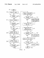
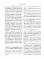
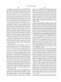
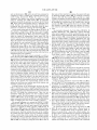
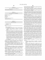
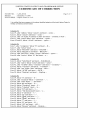
FIG. 4 is a ?oWchart shoWing a sequence of operations
mode and a second operational mode, and causes the pro
cessor portion to access and process the test de?nition,
carried out by the test system of FIG. 1;
Wherein in the ?rst operational mode the processor portion
processes both the ?rst portion and the second portion of the
to the screen of FIG. 3, but shoWing an operator log-in
test de?nition so as to carry out both of the ?rst and second
operation;
test operations, and Wherein in the second operational mode
the processor portion processes only the ?rst portion of the
test de?nition to the exclusion of the second portion thereof
includes a WindoW presenting both a graphic image and
related alphanumeric information to an operator of the test
FIG. 5 is a diagrammatic vieW of a display screen similar
FIG. 6 is a diagrammatic vieW of a display screen Which
so as to carry out only the ?rst test operation Without the
second test operation.
1O
Yet another form of the invention involves a test station
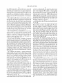
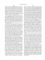
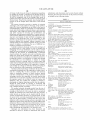
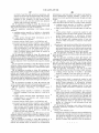
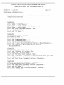
FIG. 8 is a diagrammatic vieW of a special display screen
15
used for certain special modes of operation of the test system
of FIG. 1;
FIG. 9 is a diagrammatic vieW of a special WindoW Which
can be presented on the display screen by the test system of
FIG. 1, in order to permit an operator to observe a plurality
of different variables and their values;
FIG. 10 is a diagrammatic vieW of a further WindoW
Which can be presented on a display screen by the test
coupled to the coupling portion, the memory portion, and the
output portion, the processor portion being operative in
response to the test de?nition to use the output portion to
successively communicate to an operator each of a plurality
of different manual steps Which are needed to carry out the
test de?nition.
Still another form of the invention involves a test station
Which includes: a coupling portion operable to facilitate a
detachable operative coupling of the test station to a unit to
be tested; an output portion through Which information can
be communicated to an operator, the output portion includ
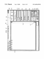
FIG. 7 is a diagrammatic vieW of a display screen similar
to FIG. 3, but also displaying information Which documents
the results of tests conducted by the test system;
Which includes: a coupling portion operable to facilitate a
detachable operative coupling of the test station to a unit to
be tested; an output portion through Which information can
be communicated to an operator; a memory portion Which
stores a test de?nition; and a processor portion operatively
system;
system of FIG. 1, in order to display information regarding
a particular variable, and to permit dynamic alteration of the
25
contents of that variable; and
FIG. 11 is a diagrammatic vieW of a display screen Which
has several WindoWs, including a WindoW for the operating
ing a video display; a memory portion Which stores a test
system, a WindoW similar to FIG. 7, and tWo additional
de?nition; and a processor portion operatively coupled to the
WindoWs Which each display information passing to and
from a test unit through respective ports of the test system
coupling portion, the memory portion, and the output
portion, the processor portion being operative in response to
of FIG. 1.
the test de?nition to display on the video display a graphic
depiction of hoW to perform a manual step required by the
test de?nition.
35
A further form of the invention involves a method of
operating a test station Which can be detachably operatively
coupled to a test unit to be tested, including: storing a test
de?nition; and causing the test station to respond to the test
de?nition by automatically carrying out on the test unit a
exemplary UUT being shoWn at 13. The exemplary UUT 13
type commonly knoWn as an optical board. HoWever, the
system 12 is also capable of testing a variety of other types
of circuit boards.
and by presenting on a display a graphic depiction of hoW to
perform a manual step required by the test de?nition.
Yet another form of the present invention involves a test
45
to a test unit Which has indicia thereon; a reader portion
Which can read the indicia on the unit; and a control portion
Which is operatively coupled to the coupling portion and the
reader portion, the control portion being responsive to
information obtained through the reader portion for carrying
out through the coupling portion at least one operation
Which is selected as a function of the information.
BRIEF DESCRIPTION OF THE DRAWINGS
A better understanding of the present invention Will be
realiZed from the detailed description Which folloWs, taken
in conjunction With the accompanying draWings, in Which:
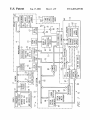
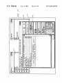
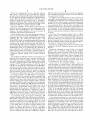
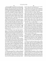
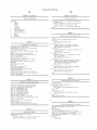
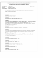
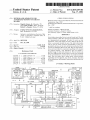
FIG. 1 is a block diagram of an apparatus Which includes
an automated test system that embodies the present inven
tion;
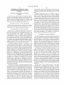
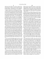
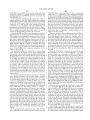
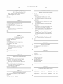
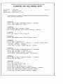
FIG. 2 is a block diagram of part of a directory structure
for a hard disk Which is a component of the test system of
FIG. 1;
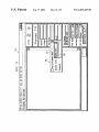
FIG. 1 is a block diagram of an apparatus 10 Which
embodies the present invention, and Which includes a test
system 12 capable of testing a unit under test (UUT), one
shoWn in FIG. 1 is a telecommunications circuit board of a
sequence of test operations speci?ed by the test de?nition,
station Which includes: a coupling portion operative to
facilitate a detachable operative coupling of the test station
DETAILED DESCRIPTION OF THE
INVENTION
55
The test system 12 includes a server 16 Which is coupled
through a netWork 17 to a netWork printer 19 and a plurality
of test stations 21—23. The netWork 17 may be any of several
different types of netWorks Which are commercially
available, and is therefore not described here in detail. The
test stations 21—23 are equivalent to each other, and there
fore only the test station 23 is illustrated and described in
detail.
The server 16 includes a processor 27, Which in the
disclosed embodiment is a commercially available micro
processor. The server 16 also includes a hard disk drive 28.
The hard disk drive 28 stores an operating system to be
executed by the processor 27, as Well as application pro
grams Which can be executed by the processor 27. In
addition, and as indicated in FIG. 1, the hard disk drive 28
stores a database ?le, an archive ?le, at least one log ?le, and
a MAC address ?le, the operational purposes of Which are
addressed later.
The test station 23 includes a tester connector 36, to Which
can be releasably coupled a UUT connector 37 that is
provided on tile UUT 13. The test station 23 further includes
a Workstation 41, Which in the disclosed embodiment is a
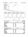
FIG. 3 is a diagrammatic vieW of a main screen provided 65
on a visual display Which is a component of the test system
commercially available computer of the type commonly
knoWn as a personal computer. It is coupled to a cathode ray
of FIG. 1;
US 6,453,435 B1
5
6
tube (CRT) display 42, a keyboard 43, and a mouse 46,
so that the Workstation 41 can control the optical poWer
Which permit a human operator to interface With the Work
meter instrument 86 through the GPIB bus 82. The optical
station 41, and to conduct tests in a manner described in
poWer meter instrument 86 includes an optical pattern
generator portion 87, and an error detection portion 88. The
test station 23 further includes an optical attenuator 93,
Which has inputs coupled to the GPIB bus 82, so that the
Workstation 41 can control the attenuator 93 through the
GPIB bus 82. The attenuator 93 is operably coupled to the
error detection portion 88 of the optical poWer meter instru
ment 86. An optical cable 96 has one end coupled to the
more detail later. A bar code reader 47 is coupled to the
Workstation 41. In the disclosed embodiment, the bar code
reader 47 is a hand-held unit Which is coupled to the
Workstation 41 by a cable that is several feet long. HoWever,
the bar code reader 47 could alternatively be a stationary
device.
The Workstation 41 includes a processor 51, Which is a
optical pattern generator 87, and its other end can be
detachably coupled to the UUT 13.
A further optical cable 97 has one end coupled to the
attenuator 93, and its other end can be detachably coupled to
commercially available microprocessor, and includes a hard
disk drive 52. The directory organization of the hard disk
drive 52, and certain ?les stored thereon, are discussed in
more detail later With reference to FIG. 2. The processor 51
eXecutes a commercially available operating system, Which
in the disclosed embodiment is the operating system avail
15
able from MicroSoft Corporation of Redmond, Washington
the UUT 13.
The UUT 13 is a circuit board, Which has thereon a header
101, to Which an end of the parallel cable 77 can be
under the tradename WINDOWS 95. The operating system
releasably coupled, and circuitry 102 de?ning a netWork
is not shoWn in the draWings, but is stored on the hard disk
drive 52. The Workstation 41 includes a netWork interface
port Which includes a connector to Which one end of the
card 53, Which is a commercially available part, and Which
couples the Workstation 41 to the netWork 17.
The Workstation 41 has a standard RS232 serial port 61,
Which is coupled to a serial-to-parallel conversion circuit 63
disposed in the test station 23. The circuit 63 is in turn
coupled to a plurality of bidirectional drivers 64 that are
coupled to the test connector 36. The Workstation 41 also
netWork cable 79 can be releasably coupled. The UUT 13
further includes an optical connector 103 to Which one end
of the optical cable 97 can be releasably coupled, and a
further optical connector 104 to Which one end of the optical
cable 96 can be releasably coupled. The UUT 13 has
circuitry 107 thereon, Which is electrically coupled to the
25
102. The circuitry 107 includes one or more electro-optical
devices, Which operatively couple the circuitry 107 to the
includes a digital input/output (I/O) card 67, Which is a
optical connectors 103 and 104.
commercially available plug-in card.
The circuitry 107 includes a processor 111 Which is a
The test station 23 includes a plurality of electronic
sWitches, tWo of Which are shoWn at 68 and 69. The test
station 23 includes a plurality of the sWitches 68 and also a
microprocessor of a commercially available type. The cir
cuitry 107 further includes three programmable devices 112,
113 and 114. In the disclosed embodiment, the device 112 is
plurality of the sWitches 69, but for clarity and convenience
a ?ash memory, the device 113 is a lattice device, and the
only one sWitch 68 and one sWitch 69 are shoWn in FIG. 1.
The sWitch 69 has one end coupled to ground, and the sWitch
68 has one end coupled to a pull-up resistor 72, the other end
UUT connector 37, the header 101, and the netWork port
device 114 is an Electrically Erasable Programmable Read
35
of the resistor being coupled to a supply voltage. The
opposite end of each of the sWitches 68 and 69 is coupled to
Only Memory (EEPROM), but the devices 112—114 could
alternatively be other types of programmable devices. The
digital I/O card 67, as shoWn diagrammatically by broken
UUT 13 has thereon a label 117, Which has indicia in the
form of a bar code on it, and possibly some other indicia.
The bar code on the label 117 provides information such as
a board number and part number, and also a serial number.
The board number and part number have a one-to-one
lines in FIG. 1.
The Workstation 41 includes a standard bidirectional
board. In contrast, the serial number is a unique number
a respective terminal of the tester connector 36. The
sWitches 68 and 69 are each operatively controlled by the
parallel port 76, and the test station 23 includes a parallel
cable 77 Which is coupled at one end to the parallel port 76,
and Which can be releasably coupled at its other end to the
UUT 13. The Workstation 41 further includes standard
circuitry providing a netWork port 78, such as that com
monly knoWn by the tradename ETHERNET. The test
station 23 includes a netWork cable 79 Which has one end
coupled to the ETHERNET port 78, and Which can be
releasably coupled at its other end to the UUT 13.
relationship to each other, and de?ne a particular type of
provided for each board of a particular type. If the part
45
number of the manufacturer is different from the part num
ber of a customer, the bar code on label 117 could also
optionally include the customer part number, as a conve
nience to the customer.
The particular UUT 13 shoWn in FIG. 1 is one particular
type of circuit board, Which has been selected for the sake
of eXample. In particular, and as mentioned above, the UUT
13 is a telecommunications circuit board of a type com
The Workstation 41 includes a circuit 81, Which is a
monly knoWn as an optical board. HoWever, the test station
General Purpose Interface Bus (GPIB) interface circuit, and
23 is designed to be capable of testing a variety of different
Which interfaces the Workstation 41 to a GPIB bus 82. The 55 types of circuit boards, Which may each have a larger or
GPIB bus 82 and the interface circuit 81 conform to an
smaller number of components than the UUT 13 shoWn in
industry standard speci?cation knoWn as the General Pur
pose Interface Bus speci?cation. Accordingly, bus 82 and
FIG. 1. For eXample, other boards may lack the optical
connectors 103 and 104, or may lack programmable devices
circuit 81 are not described here in detail.
The test station 23 includes a poWer supply 83, Which is
coupled to the GPIB bus 82, so that the poWer supply 83 can
such as those shoWn at 112-114. Each operator has an
identi?cation badge or card, one of Which is shoWn at 121.
The badge 121 has a bar code label 122 on it. The bar code
be controlled by the Workstation 41 through the GPIB bus
82. The poWer supply 83 has outputs Which are coupled to
lar operator, such as a name and/or employee number.
the tester connector 36, so that the poWer supply 83 can
supply poWer to the UUT 13.
The test station 23 also includes an optical poWer meter
instrument 86, Which has inputs coupled to the GPIB bus 82,
label 122 includes information Which identi?es the particu
Although it Would be possible for each operator to manually
65 enter this information, use of a machine-readable card or
badge reduces the chance of-inadvertent errors by the opera
tor.
US 6,453,435 B1
8
7
MAC ?le Which contains the top level of the test de?nition,
and each MAC ?le contains a portion of the test de?nition
FIG. 2 is a diagrammatic vieW of a directory structure
131, Which is a portion of the overall directory structure
present on the hard disk drive 52 of the Workstation 41 (FIG.
1). The directory structure 131 includes a HostSoft subdi
rectory 133. The HostSoft subdirectory 133 has several
additional subdirectories associated With it, including a
at a greater level of detail.
The PRG ?les and the MAC ?les are all maintained in an
uncompiled operator-perceptible format. In more detail,
each PRG ?le or MAC ?le in the disclosed embodiment is
an ASCII text ?le, Which contains a command sequence that
Programs subdirectory 136, a Macros subdirectory 137, a
PrgDevs (programmable devices) subdirectory 138, a Tables
includes one or more commands draWn from a prede?ned
subdirectory 139 and a LogFiles subdirectory 140.
set of commands. Table 1 lists all of the commands in this
The term “HostSoft” is used herein as the name of a
subdirectory, and as the name of an executable program ?le.
HoWever, the term HOSTSOFT is also a trademark of the
10
prede?ned command set, and provides a brief summary of
each command. To avoid unnecessary duplication, the vari
assignee of the present application, for use in commerce in
ous commands are not all described again in detail here.
HoWever, some speci?c comments are offered in the interest
association With products disclosed herein.
of clarity.
FIG. 2 identi?es some of the most relevant ?les Which are 15
stored in the subdirectories 133 and 136—140, but it Will be
recogniZed that each of these subdirectories may include
additional ?les. The subdirectory 133 includes a ?le
HostSoft.EXE, Which is a compiled program that is executed
by the processor 51 of the Workstation 41 in conduction With
execution of the resident operating system, and Which pro
vides underlying control for test operations carried out by
the test station 23. The subdirectory 133 also includes a ?le
HostRun.INI, Which is an initialiZation ?le described in
more detail later. The subdirectory 133 includes several
additional ?les Which each include a graphics image in a
standard “bit-map” format, and Which are each identi?ed by
a respective ?lename ending in the common extension
First, some of the commands in Table 1 refer to a “MAC
address”, Which is an industry-standard type of netWork
address. It is not necessary to discuss the MAC addresses in
detail here. HoWever, it is important to point out that the
present discussion refers to macro ?les, and some macro
?les have ?lenames Which end With the extension “MAC”,
and Which are referred to herein as MAC ?les.
References to the MAC ?les should not be confused With
25
references to the MAC addresses, because they are entirely
different.
Second, the commands set forth in Table 1 can support
different types of variables, including integer variables,
?oating point variables, and string variables. The 3G Host
Soft.EXE program is Written so as to effect automatic
“BMP”.
The subdirectory 133 also includes several lattice con
conversion betWeen variable types. Thus, for example, if one
of the commands in Table 1 is expecting a variable value of
?guration ?les, Which each have a respective ?lename that
a ?oating-point type, but receives a variable value of an
ends With the common extension “LAT”, and includes
integer type, it Will automatically convert the integer value
several ?le transfer protocol (FTP) con?guration ?les, Which
to a ?oating-point value, and then continue.
each have a respective ?lename that ends With the common 35
Third, some of the commands in Table 1 refer to a
extension “FTP”. Speci?c examples of a LAT ?le and an
“generic message” or a “generic result”. The format for each
FTP ?le are described later. The subdirectory 133 further
such command ends With one or more parameters Which are
includes several library ?les, Which have respective ?lena
disposed Within square brackets in the command de?nition.
The square brackets indicate that the parameters Within them
mes that end With the common extension “LIB”, and several
dynamic link library ?les Which have respective ?lenames
that end With the common extension “DLL”. The LIB and
are optional. Depending on Whether or not these parameters
are present in a given command, the command Will be
DLL ?les are compiled object-code ?les, as discussed later.
carried out in either a data mode or a measurement mode.
The Programs subdirectory 136 includes several program
?les, Which each have a respective ?lename ending in the
The measurement mode is in effect if the optional param
eters are present. The optional parameters include a “test
common extension “PRG”. The Macros subdirectory 137
includes several macro ?les, Which each have a respective
?lename ending in the common extension “MAC”. Speci?c
examples of a PRG ?le and several MAC ?les are discussed
45
?ag” parameter, Which affects hoW the command operates.
More speci?cally, if the test ?ag parameter is a “P” for
“pass”, then the system Will display a speci?ed message and
the Word “PASS” on the display 62 if the speci?ed operation
later. The PrgDevs subdirectory 138 includes several binary
is successful, but Will display nothing if the speci?ed opera
?les, Which each include binary information that can be
tion fails. If the test ?ag parameter is an “F” for “fail”, then
loaded into a programmable device, such as one of the
the system Will display the speci?ed message and the Word
“FAIL” if the speci?ed operation fails, but Will display
nothing if the speci?ed operation is successful. If the test
?ag parameter is an “A” for “alWays”, then the system Will
programmable devices shoWn at 112—114 in FIG. 1. The
Tables subdirectory 139 includes a database ?le, Which is
discussed in more detail later. The LogFiles subdirectory
140 includes at least one log ?le, Which is used to store the
55
results of certain test operations, in a manner described later.
As mentioned above, the Programs subdirectory 136
alWays display the speci?ed message, and Will also display
either the Word “PASS” or the Word “FAIL” in dependence
on Whether the speci?ed operation Was successful or not.
includes a plurality of PRG ?les, and the macro subdirectory
137 includes a plurality of MAC ?les. Each type of unit to
be tested is associated With a respective PRG ?le, Which
If the optional parameters are not provided, then the
command is carried out in the data mode. Data mode is used
to collect information from a device for the purpose of either
de?nes the sequence of test operations that are to be con
ducted on each unit of that type. The PRG ?le may call one
displaying it or evaluating it later. That is, the command
simply returns data to the screen or to a variable. Table 2 sets
or more MAC ?les, in a manner someWhat similar to the
forth one speci?c example of a PRG ?le, Which, has the
manner in Which a subroutine is called by a computer
name “3MR1.PRG”. This speci?c PRG ?le Was prepared to
test an optical board of the type shoWn at 13 in FIG. 1. This
PRG ?le calls several MAC ?les, some of Which call other
program. Each MAC ?le can call one or more other MAC 65
?les in a similar manner. There is no signi?cant difference
betWeen a PRG ?le and a MAC ?le. A PRG ?le is simply a
MAC ?les. In total, processing of the PRG ?le in Table 2
US 6,453,435 B1
10
requires ten related MAC ?les, Which are respectively set
forth in Tables 3—12. Tables 2—12 are self-explanatory When
read in conjunction With the de?nition of the command set
provided in Table 1. Nevertheless, an overvieW explanation
of these ?les is given later for purposes of convenience.
different colors, such as black and green, to shoW that the
indicator 154 is respectively off and on. The Test Busy
indicator 153 is turned on When the test station 23 is
conducting a test on a unit such as the UUT 13. If the unit
passes all of the tests conducted on it, then at the completion
of the test sequence, the PASS indicator 154 is turned on in
order to indicate to the operator that the unit successfully
When the compiled program HostSoft.EXE is interpreting
the PRG ?le of Table 2, or one of the MAC ?les of Tables
3—12, it reads a line, and then parses and processes that line
on the ?y in an “interpretative mode”, in order to implement
the command. The HostSoft.EXE program then reads the
next line, and processes that next line in the interpretative
mode. The present invention is not limited to the speci?c set
of commands set forth in Table 1, nor to the speci?c PRG
and MAC ?les set forth in Tables 2—12. Instead, Tables 1—12
passed all tests.
BeloW the indicators 153 and 154 is a region 157, Where
10
privileges than other operators. For example, one operator
may be permitted to run prede?ned tests on units Which are
according to the present invention, in order to facilitate a
better understanding of the present invention. The PRG and
MAC ?les in Tables 2—12 are discussed in more detail later.
When the Workstation 41 is turned on, it Will automati
to be tested, but may not have the privilege to make any
changes to those tests. In contrast, an operator With a higher
privilege level may be able to not only run the prede?ned
tests, but to also dynamically alter them.
BeloW the regions 157 and 158 are three further regions
161—163, Where the system displays information regarding
the unit Which is currently being tested. In particular, in
region 161, the system displays an alphanumeric “Test
Board” name for the speci?c type of unit currently being
tested. In the region 162, the system displays a part number
cally initiate execution of the resident operating system,
Which as mentioned above may be the WindoW-based oper
25
for that type of unit. In general, there Will be a one-to-one
relationship betWeen the test board name and the part
number. In region 163, the system displays a serial number,
Where there is a unique serial number for each unit of a given
type. That is, if there are one hundred units of the same type,
they Will each have the same test board name and part
number, but each Will have a different serial number.
Will be doWnloaded from the server 16 to the test station 23.
More speci?cally, the database ?le on the hard disk drive 28
of the server 16 Will be doWnloaded to the Tables subdirec
tory 139 on the hard disk drive 52 of the test station 23.
Further, the archive ?le on the hard disk drive 28 of the
server 16 Will be accessed, and appropriate ?les therefore
Will be extracted from the archive ?le and doWnloaded to
appropriate subdirectories 113 and/or 136—138 on the hard
disk drive 52 of the test station 23. This may include any or
158, Which displays the privilege levels enjoyed by the
current operator. Some operators Will have a Wider range of
are provided to shoW one example of a test de?nition 15
ating system available under the tradename WINDOWS 95.
Then, through use of the keyboard 43 or mouse 46, the
operator can instruct the operating system to cause the
processor 51 to begin execution of the compiled HostSoft
.EXE program located in the HostSoft subdirectory 133.
During this turn-on or initialiZation process, information
the name of the current operator is displayed, and a region
BeloW the part number region 162 are three drop-doWn
lists 167, 168 and 169, Which can be used by the operator to
selectively control certain aspects of system operation. The
35
drop-doWn list 167 is used to select the “Print Mode”, Which
determines What information, if any, Will be printed on the
netWork printer 19 (FIG. 1) by the test station 23. The three
all of the above-discussed INI, BMP, LAT, FTP, DLL, LIB,
PRG, MAC and binary ?les. In the disclosed embodiment,
available options for print mode are “Don’t Print”, “Print On
Errors” and “AlWays Print”, Which are self-explanatory.
some of these ?les are doWnloaded in conjunction With
The drop-doWn list 168 is used to select the “Test Mode”.
The tWo available Test Mode options are “Stop On Errors”
and “Continue On Errors”, Which specify Whether or not the
system is to continue if it detects an error While conducting
start-up of the operating system, and others are doWnloaded
if and When the HostSoft program is started. HoWever, it Will
be recogniZed that all ?les could be doWnloaded at the same
time.
a test.
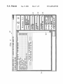
As soon as the HostSoft.EXE program is started, it Will 45
The third drop-doWn list 169 is used to select the “Test
generate and present on the display 42 a WindoW containing
Items”, Which alloWs the operator to specify hoW rigorously
a main screen, Which is shoWn at 146 in FIG. 3. The main
screen 146 is a WindoW having at the top a title bar 147,
a particular unit should be tested. The tWo available options
are “Normal” and “Sample Base”. The “Sample Base”
option is typically used to cause more rigorous testing to be
Which has an industry-standard format. In particular, the
icons at the right and left ends of the title bar 147 may be
carried out than the “Normal” option, in a manner Which is
described in more detail later. Units Will usually be tested
used to resiZe or to close the WindoW Which contains the
main screen 146. Immediately beloW the title bar 147 is a
menu bar 148, Which is described in more detail later. BeloW
the menu bar 148, on the left side of the screen, is a
Workspace 151, Which can be used to display information to
the operator, including information received from the opera
tor. At the right side of the Workspace 151 is a scroll bar 152
of standard format, Which permits the operator to scroll up
under the “Normal” option. The “Sample Base” option
might be periodically selected in order to effect more rig
55
orous testing of a feW units for quality control purposes, for
example once per Week or once per month. Alternatively, if
a particular unit has exhibited problems in the ?eld but
appears to pass all tests conducted under the “Normal”
option, the “Sample Base” option might be selected in order
and doWn through the information present in the Workspace
to effect more rigorous testing of that particular unit, in an
151.
BeloW the menu bar 148, on the right side of the screen,
is a Test Busy indicator 153. The Test Busy indicator 153 is
a portion of the screen Which is selectively presented at
attempt to identify and localiZe the problem.
can be actuated in order to initiate a selected test, in a
different times in one of tWo different colors, such as gray
manner described later. The button 173 is used to toggle
and red, in order to indicate that the indicator is respectively
off and on. Adjacent the Test Busy indicator 153 is a PASS
indicator 154, Which can also be displayed in one of two
TWo buttons 172 and 173 are provided beloW the drop
doWn list 169. The button 172 is a “Start Test” button, Which
65
betWeen “Log On” and “Log Off” modes of operation, in
Which test results are and are not saved to a log ?le in the
LogFiles subdirectory 140 (FIG. 2), as discussed later.
US 6,453,435 B1
11
12
operator. At block 202 in FIG. 4, the system Waits for the
operator to enter the passWord in the region 198 of WindoW
196, and then checks to make sure that the entered passWord
is the correct passWord for the particular operator. The
Turning noW in more detail to the menu bar 148, the menu
bar identi?es ?ve drop-doWn menus, Which are the File
Menu 176, Options Menu 177, Test Menu 178, Tools Menu
181, and Help Menu 182. The Help Menu 182 provides
on-line help in a generally standard manner, and is not
described in detail here. As to the other drop-doWn menus,
the most pertinent options from each menu Will be
described, but it Will be recognized that these menus may
each have additional options Which are not described here.
The File Menu 176 has an “Open Macro” option, Which
opens a special WindoW that Will be described in more detail
later in association With FIG. 8. The File Menu also has
“Exit” option, Which causes the test station 23 to terminate
execution of and exit from the HostSoft.EXE program.
The Options Menu 177 has a “View Pictures” option,
Which toggles on and off a vieW pictures capability, Which is
described in more detail later. The Options Menu also has a
system uses the operator name or number to access a table
stored on the hard disk drive 52, in order to obtain the
current passWord for that particular operator. If the passWord
entered by the operator does not match the passWord from
the table, the operator may be alloWed to try entering the
10
passWord a second time. HoWever, if the operator is not able
to enter the correct passWord after a reasonable number of
attempts, control is returned to block 193, to Wait for a
different operator to scan the bar code label on his or her
operator badge.
15
“Debug Mode” option, Which toggles on and off Whether the
system is operating in a special debug mode, Which Will be
Once the correct passWord has been entered, control
proceeds from block 202 to block 203, Where the system
Waits for the operator to authoriZe the system to begin a test,
either by actuating the Start Test button 172 or by selecting
the Start Test option from the Test Menu 178. Once the
operator starts a test, control proceeds from block 203 to
block 206, Where the system prompts the operator to use the
described in more detail later. The Options Menu also
includes a “Step Mode” option, Which toggles on and off a
bar code reader 47 to scan the bar code label 117 on the UUT
Which is described in more detail. Further, the Options Menu
includes a “Log Test Results” option, Which is a toggle that
13 Which is to be tested. The system Waits for the bar code
label to be scanned at block 207. The information obtained
from the bar code label 117 may include the board name, the
test results to a log ?le located in the LogFiles subdirectory
Will then display in the regions 161—163 (FIG. 3) of the main
special mode of operation Which is called the step mode, and
determines Whether or not the test station 23 saves certain 25 board part number, and a serial number, Which the system
screen 146, for example as visible at 161—163 in FIG. 7.
140 (FIG. 2). The “Log Test Results” option is functionally
After the operator scans the bar code label, the system
proceeds to block 208, Where it prompts the operator to
equivalent to the button 173, Which Was discussed above.
The Test Menu 178 includes a “Start Test” option, Which
is equivalent to the above-discussed Start Test button 172.
The Test Menu further includes a “Cancel Test” option,
couple the connector 37 on the UUT 13 to the tester
connector 36 of the test station 23, and then Waits for the
operator to do so at block 209. The operator does not yet
Which immediately terminates a currently running test prior
to normal completion thereof. Further, the Test Menu
includes a “Select Macro To Run” option, Which is discussed
in more detail later.
35
The Tools Menu 181 has an “RS232 Spy” option and a
“GPIB Spy” option, each of Which toggles on and off a
special facility that can be used to vieW information going to
and from a unit being tested, in a manner discussed later.
connect to the UUT 13 any of the other cables 77, 79, and
96—97, as there Will be separate prompts later for any or all
of these cables. When the operator has coupled the connec
tors 36 and 37 together, the operator responds to the prompt
by pressing the ENTER key on the keyboard 43, or by some
other similar action, Which causes the system to proceed
from block 209 to block 212.
At block 212, the system turns on the Test Busy indicator
FIG. 4 is a ?oWchart shoWing the general sequence of
operations in the portion of the HostSoft.EXE program
153, in particular by changing this portion of the screen from
Which carries out testing of a given unit under test. With
respect to this portion of the program, execution begins at
block 191, at Which point the HostSoft.EXE program is
such as red. Then, a search is made of the HostRun.INI ?le
a subdued color such as gray to a more pronounced color
45
presenting on the display 42 (FIG. 1) the main screen 146
shoWn in FIG. 3. Control proceeds from block 191 to block
192, Where the system makes sure that the PASS indicator
154 (FIG. 3) is off, for example by setting the letters “PASS”
to a subdued color such as black. Then, at block 193, the
system Waits for an operator to use the bar code reader 47 to
scan the bar code label 122 on the badge 121 of that
number is “H16B-1023-H362”, and the corresponding
particular operator. The bar code label provides the name of
the operator, or an operator number from Which the name of
the operator can be determined. The bar code label 122 may
55
optionally provide information regarding the privilege level
of that particular operator, although the privilege level may
alternatively be obtained by using the operator name or
number to access a table of privilege information stored on
the hard disk drive 52.
With reference to FIG. 5, the system superimposes on the
main screen 146 a log-in WindoW 196, and displays the name
of the operator, as determined from the badge, in a region
197 of the WindoW 196. The WindoW 196 also includes a
region 198 for the operator to enter a passWord. The display
of the WindoW 196 in FIG. 5 corresponds to block 201 in
FIG. 4, Where the system requests a passWord from the
Which, as discussed in association With FIGS. 1 and 2, is
stored in the HostSoft subdirectory 133 of the hard disk
drive 52. An excerpt from this ?le is shoWn in Table 13. It
includes a “[BOARDS]” section, Which lists the part number
of each knoWn board, folloWed by an equal sign and a
unique code. In the case of the speci?c UUT 13 Which is the
subject of this example, and as shoWn in Table 13, the part
unique code is “3MR1”. The HostRun.INI ?le also includes
a number of additional sections, each of Which corresponds
to a respective one of the unique codes. As shoWn in Table
13, there is a section “[3MR1]”, Which corresponds to the
particular UUT 13. Each such section contains certain
standard items of information, including the name of the
board, the name of the PRG ?le Which is provided to test the
board, the names of the subdirectories Which include the
PRG and MAC ?les used to test the board, and an indication
of Whether the system should have the operator verify the
65
revision number of the board. It Will be noted that the
speci?c PRG ?le identi?ed in Table 13 for the UUT 13 of
FIG. 1 is “3MR1.PRG”, Which is the speci?c PRG ?le set
forth in Table 2.
In FIG. 4, control then proceeds from block 212 to block
213, Where the system checks to see Whether the “Requir
US 6,453,435 B1
13
14
eRevision” parameter in the HostRun.INI Was “Yes”. If so,
value such “OSFE” and a second checksum value such as
control proceeds to block 214, Where the system prompts the
“F97D”. At this point in time, for the particular UUT 13
Which is to be tested, the system has already obtained the
board part number (for eXample at blocks 206—207 in FIG.
4), has already obtained the board revision number if there
is one (for eXample at blocks 213—214 in FIG. 4), and has
operator to enter a revision number Which is visible on the
UUT 13, and the system then stores this revision number for
later use. Control ultimately continues at block 217, Where
the system uses the “ProgramDir” parameter of the HostRu
obtained an identi?er (for eXample “IC34” from the macro
n.INI ?le to identify the subdirectory containing the speci
in Table 5). The system then searches the database of Table
?ed PRG ?le, Which in this case is the Programs subdirec
tory 136 of FIG. 2. The system then retrieves from this
14 in an attempt to ?nd a record With a matching part
number, revision number and identi?er. If the test station 23
does not ?nd a matching record in the database of Table 14,
Which is stored on the local hard disk drive 52 of FIG. 1, then
subdirectory the PRG ?le Which is speci?ed by the “Pro
gramFile” parameter of the HostRun.INI ?le, Which in this
case is the “3MR1.PRG” ?le shoWn in Table 2.
Control then proceeds to block 221, Where the HostSof
t.EXE program being eXecuted by the processor 51 pro
cesses the 3MR1.PRG ?le shoWn in Table 1 in an interpre
tative manner, as already discussed above. As this is carried
the test station 23 Will interact With the server 16 in order to
search the database ?le stored on the hard disk drive 28 of
the server 16. The database ?le in the server 16 may be more
15 up to date, and may thus include a record that matches the
search parameters. In the instant eXample, it is assumed that
out, this PRG ?le Will directly and indirectly invoke ten
a match is found in the database of Table 14, so that the
macro ?les, Which are the MAC ?les shoWn in Tables 3—12.
Based on the “MacroDir” parameter in the HostRun.INI ?le
system obtains the lattice con?guration ?lename
“OptBd.LAT”, and the tWo associated checksums.
The system Will then retrieve the OptBd.LAT con?gura
tion ?le from the HostSoft subdirectory 133 (FIG. 2),
(Table 13), the system knoWs that these MAC ?les are all
located in the Macros subdirectory 137 of FIG. 2. As
discussed above, these MAC ?les Will also be processed in
exemplary contents of Which are shoWn in Table 15. The
information in this lattice con?guration ?le includes the term
“PrgDevs\7503H999.jed”, Which is an identi?cation of a
an interpretative mode.
As eXplained above, the PRG and MAC ?les shoWn in
Tables 2—12 are provided primarily by Way of eXample, and
are self-explanatory When considered in conjunction With
25
the command set forth in Table 1. Thus, a detailed discussion
connectors 36 and 37 (FIG. 1) to the processor 111 on the
UUT 13, Which in turn programs the contents of this binary
?le into the lattice device 113. It Will be noted that, in this
of every step Which occurs during interpretation of these
speci?c PRG and MAC ?les is not necessary. HoWever, a
brief overvieW Will be provided as a convenience, and
certain selected steps Will be discussed in more detail.
More speci?cally, the folloWing is an overvieW of What
manner, the test station 23 ensures that the lattice device 113
on the UUT 13 is correctly programmed With the most
up-to-date version of the ?rmWare associated With the
particular part number and revision number for the UUT 13.
happens in block 221 during processing of the speci?c
exemplary PRG and MAC ?les Which are set forth in Tables
2—12. It is important to recogniZe that these correspond
directly to testing of one particular type of unit to be tested,
Which is the optical telecommunications board 13 shoWn in
FIG. 1. Substantially different PRG and MAC ?les might be
binary ?le named “7503H999.jed”. This binary ?le is
located in the PrgDevs subdirectory 138 (FIG. 2). The
system retrieves this binary ?le, and supplies it through the
35
This is all handled automatically, Without operator
involvement, thereby substantially avoiding the possibility
of error.
Then, the processor 111 on the UUT 13 uses the checksum
information from the database (Table 14) to verify that the
used to test other units. The 3MR1.PRG ?le of Table 2 is
primarily a sequence of calls to various MAC ?les.
doWnload of information into the lattice device 113 has been
accurately and successfully completed. The macro of Table
More speci?cally, and With reference to Table 2, the
5 receives a return value from the command Which effected
3MR1.PRG ?le begins by calling the InitialiZeEquipment
the ?rmWare doWnload, and the macro checks the return
.MAC macro, Which is shoWn in Table 3. This macro then
value in order to determine Whether the doWnload Was
calls the PoWer.MAC macro shoWn in Table 4, Which turns 45 successful. Control then returns to the PRG ?le of Table 2,
on and con?gures the poWer supply 83 (FIG. 1) for the UUT
Which calls the OpticalPoWerTest.MAC macro of Table 6.
13. Then, the InitialiZeEquipment.MAC macro of Table 3
This macro in turn calls the MeasureOpticalPoWer.MAC
interprets several commands that initialiZe the optical poWer
meter instrument 86, folloWed by commands that initialiZe
the optical attenuator 93 and the serial port 61.
macro of Table 7, Which interacts With the optical poWer
meter instrument 86 (FIG. 1) so as to carry out an optical
poWer measurement. The results are then evaluated, and
control ultimately returns to the PRG ?le of Table 2.
Then, the 3MR1.PRG ?le of Table 2 carries out a com
Control then returns to the 3MR1. PRG ?le of Table 2,
Which calls the FirmWareDoWnloadTest.MAC macro shoWn
in Table 5. In general, this macro effects programming of the
lattice device 113 on the UUT 13, by doWnloading into it a
?le of binary information. In this regard, the second com
mand Which displays a message telling the operator to
“Connect the optical cables as shoWn in the picture”, While
55
simultaneously displaying a picture shoWing hoW to do this.
mand in the macro includes a reference to an identi?er
The displayed picture is obtained from the bit-map graphics
“IC34”, Which may be an integrated circuit number of the
part to be programmed, and Which Will be used as a search
parameter Within the database ?le located in the Tables
?le “Optical.BMP”, Which is one of the BMP ?les located in
subdirectory 139 (FIG. 2). In this regard, the database ?le in
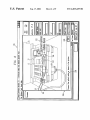
WindoW 226 over part of the main screen 146, the upper
the subdirectory 139 includes a programmable device
database, an eXcerpt from Which is shoWn in Table 14.
With reference to Table 14, each record in the database
includes siX ?elds, the ?rst of Which is a board part number
portion of the WindoW 226 being a direct display of the
Optical.BMP ?le, and the loWer portion of the WindoW
containing the speci?ed message at 228, along With an “OK”
button 229. In the disclosed embodiment, the BMP infor
mation displayed in the upper portion of the WindoW 226 is
such as “H16B-1023-H362”, a board revision number such 65
the HostSoft subdirectory 133 (FIG. 2). In more detail, and
as shoWn in FIG. 6, the system superimposes a special
as “002A”, an identi?er such as “IC34”, the name of a
a digitiZed photograph, but it could alternatively be a com
con?guration ?le such as “OptBd.LAT”, a ?rst checksum
parable diagram.
US 6,453,435 B1
15
16
In FIG. 6, the BMP image displayed in the upper portion
locations and to verify that the contents are correct, and then
of the window 226 is an accurate view of the test station 23
returns a result back to the HostSoft program.
and the UUT 13 as they actually appear to the operator. This
Next, the PRG ?le of Table 2 calls a PowerConsumption
image shows the operator where the optical connectors 103
Test.MAC macro, which is shown in Table 10. This macro
and 104 are physically located on the UUT 13, and shows
how the optical cables 96 and 97 should properly be routed
to and coupled to these connectors 103 and 104. The image
itself includes a legend 232, which says “Connect optical
cables here”, and includes an arrowhead pointing to the
optical connectors. This image helps an inexperienced
operator to remember to connect the optical cables, to do so
at the proper point in the test sequence, and to easily and
interacts with the power supply 83 in order to determine the
current level of power consumption of the UUT 13, and then
evaluates this current level of power consumption.
Thereafter, the PRG ?le of Table 2 calls a production
10
ming of the ?ash memory 112 on the UUT 13, using a ?le
transfer protocol (FTP) download. This is carried out in a
manner which, in general, is similar to the above-described
sequence by which the lattice device 113 is programmed. In
correctly connect the cables, all without extensive training.
Given that the test station 23 is capable of testing a number
of different types of units, a new operator can accurately and
reliably conduct tests on a wide range of units, without
15
undergoing an extensive training process.
While the particular BMP image, message 228 and legend
232 in FIG. 6 all have to do with the connection of optical
cables, it will be recogniZed that a sequence of equivalent
windows containing other images and messages could be
used to lead an operator through the manual steps needed in
order to effect testing of a particular type of unit. It will also
be recogniZed that a window similar to window 226 could be
used to request an operator to provide input information. For
brief, the system takes the board part number, the board
revision number (if any), and the identi?er “IC3, IC4”
obtained from the macro of Table 11, and searches the
database of Table 14. If necessary, the database in the server
16 is also searched. When a match is found, the system
obtains the name of an FTP con?guration ?le such as
“OptBd.FTP”, and two checksum values.
The system retrieves the FTP con?guration ?le OptBd
.FTP from the HostSoft subdirectory 133, the exemplary
25
example, if a particular type of circuit board has a light
emitting diode (LED), the system could display a BMP
image showing the board and the location of the LED
contents of which are shown in Table 16. The information in
this FTP con?guration ?le includes parameters which will
control the FTP transfer, as well as a path identifying a
binary ?le which is to be downloaded into the ?ash memory
112. The system then transfers the binary ?le to the proces
sor 111, which programs it into the ?ash memory 112. From
thereon, with a request that the operator actuate one of two
displayed buttons in dependence on whether the LED is
the point of view of the calling macro ?le, the primary
difference between the commands which respectively pro
currently on or off.
It was mentioned above that the Options Menu 177 (FIG.
3) has a “View Pictures” option. This option permits an
operator to selectively permit or suppress the display of the
BMP image in each window of the type shown at 226 in FIG.
6. That is, if the operator enables the “View Pictures” option,
the BMP image will be displayed in each such window, in
software download macro ProdSoftwareDownload.MAC,
which is shown iii Table 11. This macro effects program
gram the lattice device 113 and the ?ash memory 112 is that
the former automatically evaluates the checksums, whereas
35
the latter does not. Thus, if checksum evaluation is desired
in the case of the FTP transfer, it must be done by providing
additional commands within the macro.
a manner similar to window 226 of FIG. 6. On the other
After completion of the ProdSoftwareDownload.MAC
hand, if the operator has disabled the “View Pictures”
option, the BMP image would not be displayed, and thus the
window 226 of FIG. 6 would present only the message 228
and the button 229, without any BMP image.
macro shown in Table 11, the PRG ?le of Table 2 calls the
ShutDown.MAC macro of Table 12, which simply calls the
Power.MAC macro of Table 4 in order to turn off the power
When the operator has properly connected the optical
cables, and has thus complied with the request presented by
the window 226, the operator actuates the “OK” button 229,
providing a window similar to that shown at 226 in FIG. 6,
supply 83. Then, the PRG ?le of Table 2 concludes by
out a call to the macro PhysicalInventoryCheck.MAC,
except that the BMP image and the message instruct the
operator to disconnect the optical cables 96 and 97 from the
UUT 13.
As the test station 23 is processing the PRG and MAC
?les of Tables 2—12, these ?les output successive messages
to the workspace 151 of the main screen 146 (FIG. 3), to
which is shown in Table 8. This macro begins by retrieving
indicate whether each test operation conducted on the UUT
45
in order to indicate to the system that the requested manual
task has been completed. The system then removes the
window 226 from the screen. Thereafter, the PRG ?le carries
from the HostSoft subdirectory 133 (FIG. 2) a library ?le
13 has passed or failed. Assuming that all the test operations
“PhyInv.LIB”, which is a compiled ?le. The system loads
and in due course executes this library ?le, which requests
information from the HostSoft program regarding what
conducted by the PRG and MAC ?les of Tables 2—12 are
board is being tested, then writes physical inventory infor
successful, then when processing of all these ?les reaches
completion, the information displayed in the workspace 151
55
identi?es successive tests which were conducted, and the
fact that the UUT 13 passed each such test. If the UUT 13
mation through the processor 111 to the EEPROM 114 of the
UUT 13, then veri?es that the information was stored
correctly, and then returns a result back to the HostSoft
program.
Control returns to the PRG ?le of Table 2, which then
calls a MemoryTest.MAC macro. The MemoryTest.MAC
macro is shown in Table 9, and performs a memory test. This
macro includes loading and execution of a compiled library
?le “MemTest.LIB”, which requests information from the
HostSoft program to determine what board is being tested,
then writes pattern information to all locations of testable
memory on the UUT 13, then reads all such testable memory
will be that shown in FIG. 7. In particular, this information
had failed any test, the information displayed in workspace
151 would indicate this.
Referring again to the ?owchart of FIG. 4, when the
system has completed interpretative processing of the PRG
and MAC ?les of Tables 2—12, control proceeds from block
221 to block 241, where the system checks to see whether
logging is enabled. As discussed above, the operator can
65
selectively toggle logging on and off, using either the button
173 (FIG. 3), or the “Log Test Results” option of the Options
Menu 177. If logging is enabled, then control proceeds from
US 6,453,435 B1
17
18
block 241 to block 242, Where the test station 23 stores
certain test results in a log ?le Which is located in the
“MACRO name”, Where the name of macro of interest is
LogFiles subdirectory 140 (FIG. 2) of the local hard disk
drive 52 (FIG. 1).
to open a special WindoW With editing capabilities, in Which
is displayed an ASCII teXt listing of the speci?ed MAC or
PRG ?le. In the disclosed embodiment, the HostSoft.EXE
program does this by invoking a special WindoW Which is an
“name.MAC” or “name.PRG”. This causes HostSoft.EXE
In the disclosed embodiment, the information Which is
logged includes at least the board number, part number,
inherent feature of the resident operating system, and Which
permits a ?le to be opened, edited, saved, and closed. Since
serial number, operator name, and an indication of Whether
or not the board passed each of the tests Which Were
conducted on it. This system could optionally log more
information or less information. The server 16 of FIG. 1 is
programmed to periodically use the netWork 17 to interro
10
this special WindoW is an inherent feature of the resident
operating system, it is not illustrated and described here in
detail. HoWever, it Will be recogniZed that the HostSoft.EXE
gate the log ?les located in the LogFiles subdirectory 140,
program could be Written to provide such a WindoW on its
and to transfer.information from these ?les to a log ?le
located on the hard disk drive 28 of the server 16.
oWn, rather than by invoking a WindoW feature of the
From blocks 241 and 242, control ultimately proceeds to
block 243, Where the system turns off the Test Busy indicator
153, in particular by changing this portion of the screen from
resident operating system.
15
a noticeable color such as red to a subdued color such as
gray. Then, at block 246, the system checks to see if the UUT
13 passed all of the tests Which Were conducted on it. If so,
control proceeds to block 247, Where the system turns on the
PASS indicator 154, for eXample by changing the letters
“PASS” from a subdued color such as black to a noticeable
color such as green. In either case, control ultimately pro
ceeds to block 248, Which represents completion of the
testing of the UUT 13.
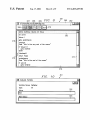
As mentioned earlier, the system has a special debug
mode, Which can be toggled on and off by selecting the
25
master de?nition of the macro With the modi?ed version
from the local disk drive, the operator must effect a standard
?le transfer operation in order to copy the modi?ed macro
?le from the local hard disk drive 52 to the server hard disk
drive 28.
When the debug mode is enabled, the operator also has
the capability to set one or more breakpoints, or in other
Words to identify any command in a PRG ?le or MAC ?le
as a breakpoint. When the system is processing a PRG or
Debug Mode option from the Options Menu 177 (FIG. 3).
When debug mode is not enabled, then the system Will test
the UUT 13 by carrying out the entire test de?nition set forth
in the PRG and MAC ?les Without stopping, eXcept in
certain limited circumstances. In particular, it Will tempo
rarily stop When a PRG or MAC ?le requests an action by
or some input from the operator, for eXample a request that
the operator effect connection of the optical cables as
When the operator is done modifying the selected PRG or
MAC ?le, the operator saves the modi?ed ?le and then
closes the special WindoW. When the modi?ed macro is
saved, the modi?ed version thereof is located only on the
local hard disk drive 52, and not in the master de?nition of
that macro in the archive ?le on the hard disk drive 28 of the
server 16. If the operator ultimately Wants to replace the
MAC ?le and reaches a command Which has been desig
nated as a breakpoint, the system stops and Waits for
operator authoriZation to proceed With processing of the
breakpoint command. In the disclosed embodiment, the
35
operator sets or clears a breakpoint in the folloWing manner.
The operator selects the “Open Macro” option from the File
Menu 176 (FIG. 3), Which then presents to the operator a
discussed above in association With FIG. 6, or a request that
the operator read and input the current state of an LED on
the unit under test. In addition, if the operator has used the
illustrated WindoW containing a list of macro ?les located in
the Macros subdirectory 137 (FIG. 2). The operator selects
Test Mode drop-doWn list 168 to select the “Stop On Errors”
mode of operation, the system Will stop if it detects any error
during the test.
from this list the macro of interest, and the system then
opens a special Open Macro WindoW 261, Which is shoWn
in FIG. 8 in a manner superimposed over the entirety of the
main screen 146. Across the top of the Open Macro WindoW
261 is an industry standard title bar 260, and under the title
In contrast, When the debug mode is enabled, it provides
some special capabilities Which permit greater operator
interaction While a test is being carried out. This can be used 45 bar 260 is a button bar 262. The button bar 262 has a GO
button 266, a STOP button 267, a STEP THROUGH button
to develop and/or debug a PRG or MAC ?le, or to make
268, a STEP OVER button 269, and an INSPECT VARI
temporary modi?cations to a PRG or MAC ?le for the
ABLES button 270. The buttons 266—270 are each discussed
purpose of isolating an elusive problem in a particular unit
in more detail later.
being tested. As soon as the debug mode is turned on, a
special prompt Will appear in the Workspace 151 of the main
BeloW the button bar 262, the Open Macro WindoW 261
has a Workspace 276, along the right side of Which is a
vertical scroll bar 277. Along the left side of the Workspace
screen 146 (FIG. 3). This debug prompt is “Debug>”.
FolloWing the debug prompt, the operator can type any
proper command from the command set of Table 1, and that
command Will immediately be interpreted When the operator
ends the command by pressing the ENTER key on the
55
276 is a breakpoint column 278. The ASCII teXt from the
selected macro ?le is displayed in the Workspace 276. In
order to specify that a particular command is to be a
of a macro ?le after the debug prompt, and that macro ?le
breakpoint, the operator selects the line Which contains that
command, for eXample by clicking on that line through use
Will be immediately interpreted. Similarly, the operator can
of the mouse 46 (FIG. 1). The system responds by displaying
type the name of a PRG ?le, and the PRG ?le, along With
any associated MAC ?les, Will be immediately interpreted.
a check mark
in the breakpoint column 278 and imme
diately to the left of the selected line, for eXample as shoWn
During the debug mode, the operator can also use the “Select
Macro To Run” option from the Test Menu to specify a
macro, Which Will be immediately interpreted. The “Select
Macro To Run” option Works only When the debug mode is
enabled.
again, the command Will be deselected as a breakpoint, and
the check mark 279 Will be removed.
After setting or clearing a breakpoint, the operator can
close the WindoW 261 or leave it open. If the WindoW 261 is
keyboard 43. Alternatively, the operator can type the name
In the debug mode, the operator can alter a PRG or MAC
?le. In particular, at the debug prompt, the operator may type
at 279. If the operator clicks on that same command line
65
left open, then When that particular macro is being processed
in an interpretative mode by the system, a highlighted region
US 6,453,435 B1
19
20
such as that shown at 282 Will be moved from command to
command in order to identify the command Which is cur
rently being interpreted. While the macro is being
that name of that variable. In response, the system Will open
an Evaluate Variable WindoW 301, an example of Which is
shoWn in FIG. 10. The WindoW 301 is speci?c to a single
interpreted, the operator can halt the interpretation at any
variable, and displays for that variable the same information
point by actuating the STOP button 267. To thereafter
Which Was shoWn in the VieW Variables WindoW 291 of FIG.
continue execution, the operator can actuate the GO button
266. If the system automatically stops at a particular com
mand because that command has been speci?ed as a
breakpoint, then the operator can thereafter cause the inter
pretation to continue by actuating the GO button 266.
9, including the variable name, the variable type, and the
10
As previously mentioned, the Options Menu 177 (FIG. 3)
As previously discussed, the Tools Menu 181 (FIG. 3)
includes “RS232 Spy” and “GPIB Spy” options. Selecting
also includes a “Step Modie” option, Which is used to toggle
a step mode capability on and off. The step mode is a further
feature of the debug mode. When step mode is enabled, and
When the system is interpreting a given macro ?le, the
15
system Will stop before interpreting each command, and Will
Wait for authoriZation to proceed to interpret the command.
Thus, the operator can step through the command sequence
in that given ?le, one command at a time. More speci?cally,
the operator does this by actuating either the STEP
display of input and output data passing through the serial
port 61 (FIG. 1), for example in a hexidemical format.
Similarly, the WindoW 313 is the GPIB Spy WindoW, Which
provides a scrolling visual display of input and output data
passing through the GPIB interface 81. The WindoWs 312
command set shoWn in Table 1, then the buttons 268 and 269
Will both have the same effect. In particular, the system Will
25
On the other hand, if the current command is a call to a
macro ?le, the buttons 268 and 269 produce different results.
In particular, if the operator actuates the STEP OVER button
the operator turns on the debug mode, the system Will
automatically suppress logging so long as the debug mode is
called macro and in any macros Which it calls, and Will not
stop in any such called macro except for a reason Which
Would cause a stop if the step mode Was disabled. When all
enabled, and Will then automatically resume logging as soon
as the debug mode is disabled.
pertinent commands in the called macros have been pro
35
open an additional similar WindoW for the macro being
called, and single step through each of the commands in that
called macro. When the system is in step mode and com
pletes interpretation of the last command in a given macro
?le, the system Will automatically close the WindoW for that
macro if the WindoW Was automatically opened by the
system, but Will leave the WindoW open if the WindoW Was
manually opened by the operator.
A further feature of the debug mode involves the capa
bility to change the values of variables, Which include not
only internal variables used by PRG and MAC ?les, but also
variables containing data Which has been received back from
the UUT 13 during the testing process. There are tWo
techniques Which the operator can use to inspect and/or
change a variable. The ?rst technique is to sWitch to the main
WindoW 146 of FIG. 3, and to type at the debug prompt a
proper command Which is from TABLE 1, and Which has the
effect of changing the value of the variable of interest.
The second technique is to actuate the INSPECT VARI
ABLES button 270 in the Open Macros WindoW 261 of FIG.
8, Which causes the system to open a special VieW Variables
WindoW, an example of Which is shoWn at 291 in FIG. 9.
This WindoW 291 includes a list 292 of all global variables,
and a further list 293 of all local variables maintained by the
and 313 each appear When the Tools Menu is used to toggle
the associated feature ON, and each disappear When the
Tools Menu is used to toggle the associated feature OFF.
Logging of data to a log ?le in the IJogFiles subdirectory
140 (FIG. 2) is not permitted When the system is operating
in the debug mode. Accordingly, if logging is enabled When
269, the system Will interpret all applicable commands in the
cessed the system Will then stop before executing the next
command in the calling macro. In contrast, if the operator
actuates the STEP THROUGH button 268, the system Will
either option toggles on or off the associated feature, each of
Which involves a special WindoW. More speci?cally, FIG. 11
shoWs a WindoW 311 corresponding to the operating system,
shoW the WindoW 146 in a partially minimiZed siZe, and
shoWs tWo additional WindoW 312 and 313. The WindoW 312
is the RS232 Spy WindoW, Which provides a scrolling visual
THROUGH button 268 or the STEP OVER 269. If the
command in question is any one of the commands from the
proceed to interpret that command, and then Will stop before
interpreting the next command.
current value 302 of the variable. HoWever, the WindoW 301
also includes a region 303, Where the operator can enter a
neW value for that variable, Which then replaces the current
value.
45
As discussed above, the drop-doWn list 167 for the Print
Mode determines Whether information Will be printed at all
and, if so, Whether all appropriate information Will be
printed or only that information associated With errors. In
this regard, information Which is considered appropriate to
print includes all information Which is sent to a log ?le if
logging is enabled, and the information Which is shoWn in
Workspace 151 of FIG. 7.
In the foregoing discussion of hoW the PRG and MAC
?les of Tables 2—12 are interpreted, it Was explained that it
is possible for these uncompiled ?les to load and initiate
execution of a compiled ?le, such as the library routines
PhyInv.LIB and MemTest.LIB. In a similar manner, it is
possible for these uncompiled ?les to load and run a com
piled Dynamic Link Library (DLL) ?le, Which is one of the
types of ?les stored in the HostSoft subdirectory 133. When
this occurs, it is possible for the DLL ?le to continue to run
after it returns control to the calling PRG or MAC ?le, such
that some subsequent commands in the PRG or MAC ?le are
interpreted in parallel With execution of the DLL ?le. Thus,
55 tWo or more routines or “threads” can be running at the same
time. These threads can pass information back and forth
betWeen each other through variables. This alloWs simulta
neous testing of different parts of a unit under test.
As mentioned above, the Test Items drop-doWn list 169
(FIG. 3) can be used to select either a Normal mode of
operation or a Sample Base mode of operation. Table 17
current macro. Each list includes the name of the variable,
shoWs an excerpt from a macro ?le, Which includes tWo
the variable type (for example, “Int” for an integer variable),
groups of macro commands that are respectively designated
in Table 17 as Group A and Group B. The commands of
and the current value of the variable. If the operator Wishes
to change the value of a particular variable, then the operator
can select that variable from the appropriate one of the lists
292 and 293, for example by using the mouse 46 to click on
65 Group B are located betWeen an “if” command and an
“endif” command, the “if” command being conditional on
Whether the Sample Base mode is enabled. The commands