1
Application Note 007
Automatic start of a generator
General description
Minimal configuration
This application note will help you to set
your Xtender for an automatic start of a
generator as per different parameters such
as the output power, the level of battery
voltage, or a combination of several
conditions.
Range of inverters
All Xtender Series
o
Xtender
o Software vers.
Features
: 1.3.28 and higher
RCC-02/-03
Activation with set schedules
o Software vers.
: 1.3.34 and higher
Activation according to one or multiple
events :
- External command
- Voltage level of batteries
- Over temperature
- Output power
- Etc…
o RCC User level : EXPERT
Possibility to combine different
conditions.
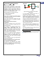
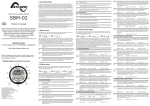
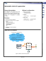
Application schematic
The generator can start with :
Temperature
Alarms
Battery level
State of the system
A combination of several conditions...
Smart-Boost active
And many other parameters...
Xtender series
Loads
AC IN
AC
AC OUT
DC
Battery
(Figure 1) Xtender connected with a generator
Page 1 / 15
AN-007-V.1.3.3-10 | © STUDER INNOTEC SA
Auxiliary contacts
Application Note 007
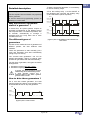
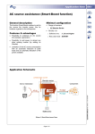
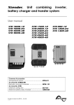
Detailed description
To start a “three wire generator”, it is necessary
to use two auxiliary relays.
This description consists of two parts.
A first, the auxiliary relay 1, as the ON/OFF of
the generator and a second, the auxiliary relay
2, as a start button (series of pulses).
The first explains how an Xtender can physically
start a generator.
A second shows the programming options for
allowing or not this start.
Aux 1
Gen. ON
(Closed relay)
Gen. OFF
Why the function “Automatic
start of a generator” ?
(Open relay)
Time
Aux 2
In actual fact, all hybrid systems require an
automatic management of the different actors
that compose them. It is therefore possible, with
an Xtender, automatically to manage a
generator and run it only when one or more
conditions are met.
Start
(Closed relay)
Stop
(Open relay)
The different types of
generators
Time
(Figure 3) Aux 1 as the ON/OFF contact and Aux 2 as
start contact
It exists on the market all kinds of generators of
different powers, but also different start
methods.
There are generators to start manually (via a
cord) and generators that start automatically
(using a key or a switch).
The “manual start generators” can not be
started automatically. Which is however quite
possible for generators that start automatically !
For this class of generator, two types are further
distinguished :
1. Generator requiring two wire contact
2. Generator requiring three wire contact
In general, only diesel generators can start
automatically, this for the following reason:
A diesel generator requires only a
preheating before a start, while a gasoline
generator needs a choke.
How to drive these generators ?
For a “two wire contact generator”, the start
requires simply the closure of one auxiliary relay
of the Xtender to start or stop the generator.
Aux 1
Start
(Closed relay)
Stop
(Open relay)
Time
(Figure 2) Aux 1 as start contact
Page 2 / 15
Application Note 007
Auxiliary contacts - Description
The Xtender inverter-charger is equipped with
two auxiliary contacts (Aux1 / Aux2) each with
one free of potential contact (reverser). These
two contacts allow multiple functions to be
carried out by using adequate cabling as well as
simple programming (for more information, refer
to the section ”Auxiliary contacts” of the RCC02/-03 user manual).
Set schedules {1269} {1378}
Xtender OFF {1225} {1333}
Xtender ON {1518} {1519}
Remote ON/OFF input active {1543} {1544}
Battery undervoltage alarm {1226} {1334}
Battery overvoltage {1227} {1335}
Inverter or Smart-Boost overload {1228} {1336}
Overtemperature {1229} {1337}
No Overtemperature alarm {1520} {1521}
Manual ON
Active charger {1231} {1339}
Manual OFF
Active inverter {1232} {1340}
Smart-Boost active {1233} {1341}
AC In present with fault {1234} {1342}
AC In present {1235} {1343}
Transfer relay drawn {1236} {1344}
Battery charging in bulk charge phase {1238} {1346}
Battery charging in absorption phase {1239} {1347}
Battery charging in equalization phase {1240} {1348}
Battery charging in floating phase {1242} {1350}
Battery charging in reduced floating phase {1243}
{1351}
Battery charging in periodic absorption phase {1244}
{1352}
Autonomy test in progress {1529} {1530}
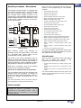
Commutation
mode
Events
combination
AND
Schedule
Program
OR
Level
REVERSE
Parameters for auxiliary contact 2
Temporal
restrictions
System
Status
Events
combination
Commutation
mode
Manual ON
AND
Manual OFF
Schedule
Program
Genset
control
Preset for an automatic starting of a 3 wire generator
Parameters for auxiliary contact 1
restrictions
System
Status
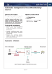
Here is the list of events that can be taken into
account in the programming of the auxiliary
contacts :
Auxiliary
contact 1
Auxiliary
contact 2
OR
Level
REVERSE
(Figure 4) Summary of programming possibilities for the
auxiliary contacts
Each auxiliary contact may therefore be
activated as per the system status, a schedule
or a particular level. These events can be
combined with an OR / AND function.
(For more information about these events, refer
to the section ”Contacts activated by an event”
of the RCC-02/-03 user manual)
List of levels
The result of this events combination may be
subject to a temporal restriction. For example, to
avoid having too much noise during the night, a
temporal restriction could be applied to prevent
the generator to start from 8:00 pm at 8:00 am.
Here is the list of particular levels (with delay)
that can be taken into account in the
programming of the auxiliary contacts :
Contact active according to the battery voltage {1245}
{1353}
Note that, if necessary, each of the auxiliary
contacts can be manually controlled.
Contact active by inverter power or Smart-Boost {1257}
{1366}
Activation of the contact 1 on battery temperature {1503}
{1504}
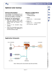
Preset for an automatic start of a generator
For an automatic start of a 3 wire generator, the
Xtender offers the possibility to activate an
enlarged function where the auxiliary contacts 1
and 2 are already pre-programmed for this
purpose.
(For more information about this events, refer to the
section ”Contacts activated by an event” of the RCC02/-03 user manual)
(For more information, refer to the section “Help for
the programming” in page 4 of this document)
List of events
The events listed on the right are being
assigned two numbers of parameters. The first
corresponds to the auxiliary contact 1 (Aux 1)
and the second corresponds to the auxiliary
contact 2 (Aux 2).
Page 3 / 15
Application Note 007
Help for the programming
The first element to be defined before any
program is the type of generator (see page 2,
The different types of generators)
For the cases listed below, we consider that the
used generator requires three wire contacts.
This is therefore necessary to active in the
“Extended functions” the parameter “Genset
control” {1491} that set the auxiliary contact
AUX 1 as the operational contact and the
auxiliary contact AUX 2 as the startup contact
(with pulse).
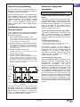
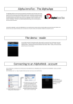
Configurable parameters for the
“Genset control”
Main contact hold/interrupt time {1574}
Some generators require an interruption of the main
contact between the cranking attempts (choke pulse).
This parameter allows to set this duration.
B.
Duration between the starter attempts {1494}
This configuration determines the duration between the
start attempts. It also determines the duration between
the activation of the operational contact and the first
attempt at restarting.
C.
Duration of starter pulse {1492}
With this configuration you can adjust the time at which
the start contact is activated.
D.
Number of startup attempts {1493}
The start contact is activated a limited number of times
in order to protect the starter if the generator has a fault.
Once the maximum number of start has been reached,
the operational contact is also deactivated. For a new
attempt to be made the condition that generated the
start must disappear and reappear.
Aux 1
Gen. ON
(Closed relay)
A
{1574}
Gen. OFF
(Open relay)
D
Time
{1493}
Aux 2
Start
(Closed relay)
B
{1494}
Stop
B
C
B
C
Parameters to configure only for the auxiliary
contact AUX 1 (the operational contact).
Contact activated with set schedules {1269}
{1378}
The auxiliary contact can also be activated like
a programmable clock. Three different weekly
programs are available. For each program, the
time frame may be applied to one or several
days of the week. If the finishing time is
programmed before the starting time, the time
frame is not taken into account.
Contact activated by an event {1455} {1456}
To be compatible with almost all the generators
of the market, four programmable parameters
are available (figure 5).
A.
Additional configurable
parameters
C
{1492}
(Open relay)
Time
The auxiliary contacts may be activated by the
states or events occurring in the installation.
Each event may be combined with another to
establish complex functions (see List of events
in page 3.
Contact activated by levels
- As per the battery voltage {1245} {1353}
- As per the inverter power or Smart-Boost {1257} {1366}
- As per the battery temperature {1503} {1504}
The auxiliary contacts can be activated on
levels such as the level of battery voltage or
temperature (see List of particular levels with
constraint p. 3). At each of these levels is
associated an activation delay. As the events,
levels may be combined with another to
establish complex functions.
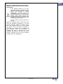
Time restrictions {1203} {1312}
These configurations allow the time frame to be
defined in which the contact should under no
circumstances be activated. Three distinct
schedules are accessible in the form of
restriction programs (programs 1 to 3). For each
program, it is possible to select the day of the
week where the restriction is activated. If the
day is selected it appears on the screen and if it
is not selected it is represented on the screen
by two horizontal lines. Once the days are
selected, it is necessary to adjust the time frame
where the restriction is active using the “starting
time” and “finishing time” configurations. If the
finishing time is programmed before the starting
time, the restriction time frame is not taken into
account.
(Figure 5) Detail of preset possibilities on the auxiliary
contact
The start is carried out by first activating the
operational contact (Aux 1) and then activating
the startup contact (Aux 2). The latter engages
several times, if necessary, to starting the
motor. If a voltage appears at the terminals of
AC IN, the startup contact is released.
Page 4 / 15
Application Note 007
Security : Limit the time of activation with a
parameter of Maximum duration of activation
{1514} {1515}
If the maximum duration for the relay
activation that you have selected is reached
and if the activation conditions are still
present
(for
instance
a
battery
undervoltage), the contact will not be
reactivated as long as the conditions are
present. Therefore there is a risk that the
auxiliary contact remains locked in this
deactivated state and you will have to reset
manually this alarm by deactivating and
then activating this parameter.
Use this function with care and only as a
security.
When the conditions are met, either one or two
relays are activated permanently. If you wish
that the activation duration is limited in time,
even if the conditions are met, you can activate
this function. Once the relay is activated, a
countdown runs according to the duration you
have selected. Once this countdown is
completed the relay is released, even if the
conditions are still there. The relay can not be
anymore activated as long as the activation
conditions have not disappeared.
Page 5 / 15
Application Note 007
Frequently Asked Questions
Remote entry
Why the function OR / AND?
AC
The parameter “Combination of events mode”
{1497} {1498} defines how the various events
intended to activate the auxiliary contact are
combined. Either a single event suffices to
activate the contact (OR function) or it must
have all the active events in order for the
contact to be activated (AND function).
AC IN
AC OUT
DC
Automatic AC
transfer switch
Battery
(Figure 6) Automatic management of two different
energy sources
As an example let us consider two events :
1 Battery undervoltage alarm
2 Overtemperature
It is also possible, requiring some wiring, to
automatically manage this generator.
If you want to activate the generator directly
when one of the events occurs, it is necessary
to activate the OR function.
However, there remains a difficulty. It may
happen that the generator does note receive the
order to stop despite the return of the main
source. It is therefore necessary to prohibit the
generator once the main source is present.
If you want the generator engages only when
both events occurs, it is necessary to activate
the AND function.
Why programmed levels with time
constraints?
Adding time constraint to one or more events
can prevent the systems constantly start and
stop the generator.
For example, if the generator starts with the
event “Battery undervoltage alarm”, the
batteries will be rapidly charged. Then, the
generator stops after a short time and will
restart when the battery voltage level is down
again. This repeated sequence is inadvisable
for the generator and the batteries.
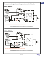
To detect the presence of the main source and
then disconnect the generator, we propose to
use a “not wired contact” of the relay K3 of the
Automatic AC transfer switch.
Thus, whatever the type of generator (2 or 3
wire), you can ensure that the generator will be
turned off once the presence of the main
source.
For more information about the wiring, see the
figure 7 and 8 on the next page
Notes
Associated application notes :
In this case, a temporal restriction would thus
start the generator only after exceeding a
certain time the low voltage level of the
batteries, but also to stop the generator only
after spending some time at the high voltage
level of batteries.
Thus, the batteries will be fully charged before
turning off the generator.
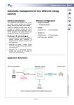
How to automatically start a generator when
it is a secondary energy source?
As described in the application note “AN005
Automatic management of two different energy
sources” it is possible to have as second energy
source a generator (figure 6).
Page 6 / 15
AN005 Automatic management of two different energy
sources
Application Note 007
Schematic wiring between the generator and the Xtender
2 wire generator
K3 *
5
6
* K3 is a relay of the “Automatic AC transfer switch” where the contact 5-6 is free.
(Figure 7) Automatic management of a 2 wire generator as second energy source
3 wire generator
K3 *
5
6
* K3 is a relay of the “Automatic AC transfer switch” where the contact 5-6 is free.
(Figure 8) Automatic management of a 3 wire generator as second energy source
Page 7 / 15
Application Note 007
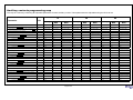
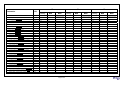
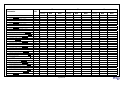
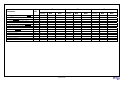
Auxiliary contacts programming map
This map is a summary containing all adjustable parameters for each auxiliary contact. These parameters are adjustable using the RCC-02/-03.
12
Parameter
24
48
Unit
Factory
Min
Max
Factory
Min
Max
Factory
Min
Max
AUXILIARY CONTACT 1
Operating mode (AUX 1 / AUX 2)
Text
Automatic
Automatic
Manual OFF
Automatic
Automatic
Manual OFF
Automatic
Automatic
Manual OFF
Combination of the events for the auxiliary contact (AUX 1 /
AUX 2)
Text
Any (Function
OR)
Any (Function
OR)
All (Function AND)
Any (Function
OR)
Any (Function
OR)
All (Function AND)
Any (Function
OR)
Any (Function
OR)
All (Function AND)
days
-- -- -- -- -- -- --
-- -- -- -- -- -- --
MO TU WE TH FR SA
SU
-- -- -- -- -- -- --
-- -- -- -- -- -- --
MO TU WE TH FR SA
SU
-- -- -- -- -- -- --
-- -- -- -- -- -- --
MO TU WE TH FR SA
SU
Temporal restrictions (AUX 1 / AUX 2)
Program 1 (AUX 1 / AUX 2)
Day of the week (AUX 1 / AUX 2)
Start hour (AUX 1 / AUX 2)
hh:mm
07:00
00:00
23:59
07:00
00:00
23:59
07:00
00:00
23:59
End hour (AUX 1 / AUX 2)
hh:mm
20:00
00:00
23:59
20:00
00:00
23:59
20:00
00:00
23:59
days
-- -- -- -- -- -- --
-- -- -- -- -- -- --
MO TU WE TH FR SA
SU
-- -- -- -- -- -- --
-- -- -- -- -- -- --
MO TU WE TH FR SA
SU
-- -- -- -- -- -- --
-- -- -- -- -- -- --
MO TU WE TH FR SA
SU
Program 2 (AUX 1 / AUX 2)
Day of the week (AUX 1 / AUX 2)
Start hour (AUX 1 / AUX 2)
hh:mm
07:00
00:00
23:59
07:00
00:00
23:59
07:00
00:00
23:59
End hour (AUX 1 / AUX 2)
hh:mm
20:00
00:00
23:59
20:00
00:00
23:59
20:00
00:00
23:59
days
-- -- -- -- -- -- --
-- -- -- -- -- -- --
MO TU WE TH FR SA
SU
-- -- -- -- -- -- --
-- -- -- -- -- -- --
MO TU WE TH FR SA
SU
-- -- -- -- -- -- --
-- -- -- -- -- -- --
MO TU WE TH FR SA
SU
Program 3 (AUX 1 / AUX 2)
Day of the week (AUX 1 / AUX 2)
Start hour (AUX 1 / AUX 2)
hh:mm
07:00
00:00
23:59
07:00
00:00
23:59
07:00
00:00
23:59
End hour (AUX 1 / AUX 2)
hh:mm
20:00
00:00
23:59
20:00
00:00
23:59
20:00
00:00
23:59
days
-- -- -- -- -- -- --
-- -- -- -- -- -- --
MO TU WE TH FR SA
SU
-- -- -- -- -- -- --
-- -- -- -- -- -- --
MO TU WE TH FR SA
SU
-- -- -- -- -- -- --
-- -- -- -- -- -- --
MO TU WE TH FR SA
SU
Program 4 (AUX 1 / AUX 2)
Day of the week (AUX 1 / AUX 2)
Start hour (AUX 1 / AUX 2)
hh:mm
07:00
00:00
23:59
07:00
00:00
23:59
07:00
00:00
23:59
End hour (AUX 1 / AUX 2)
hh:mm
20:00
00:00
23:59
20:00
00:00
23:59
20:00
00:00
23:59
days
-- -- -- -- -- -- --
-- -- -- -- -- -- --
MO TU WE TH FR SA
SU
-- -- -- -- -- -- --
-- -- -- -- -- -- --
MO TU WE TH FR SA
SU
-- -- -- -- -- -- --
-- -- -- -- -- -- --
MO TU WE TH FR SA
SU
Program 5 (AUX 1 / AUX 2)
Day of the week (AUX 1 / AUX 2)
Start hour (AUX 1 / AUX 2)
hh:mm
07:00
00:00
23:59
07:00
00:00
23:59
07:00
00:00
23:59
End hour (AUX 1 / AUX 2)
hh:mm
20:00
00:00
23:59
20:00
00:00
23:59
20:00
00:00
23:59
days
-- -- -- -- -- -- --
-- -- -- -- -- -- --
MO TU WE TH FR SA
SU
-- -- -- -- -- -- --
-- -- -- -- -- -- --
MO TU WE TH FR SA
SU
-- -- -- -- -- -- --
-- -- -- -- -- -- --
MO TU WE TH FR SA
SU
Contact active with a fixed time schedule (AUX 1 / AUX 2)
Program 1 (AUX 1 / AUX 2)
Day of the week (AUX 1 / AUX 2)
Start hour (AUX 1 / AUX 2)
hh:mm
07:00
00:00
23:59
07:00
00:00
23:59
07:00
00:00
23:59
End hour (AUX 1 / AUX 2)
hh:mm
20:00
00:00
23:59
20:00
00:00
23:59
20:00
00:00
23:59
Page 8 / 15
Application Note 007
12
Parameter
24
48
Unit
Min
Factory
Max
Min
Factory
Max
Min
Factory
Max
Program 2 (AUX 1 / AUX 2)
Day of the week (AUX 1 / AUX 2)
days
-- -- -- -- -- -- --
-- -- -- -- -- -- --
MO TU WE TH FR SA
SU
-- -- -- -- -- -- --
-- -- -- -- -- -- --
MO TU WE TH FR SA
SU
-- -- -- -- -- -- --
-- -- -- -- -- -- --
MO TU WE TH FR SA
SU
Start hour (AUX 1 / AUX 2)
hh:mm
07:00
00:00
23:59
07:00
00:00
23:59
07:00
00:00
23:59
End hour (AUX 1 / AUX 2)
hh:mm
20:00
00:00
23:59
20:00
00:00
23:59
20:00
00:00
23:59
days
-- -- -- -- -- -- --
-- -- -- -- -- -- --
MO TU WE TH FR SA
SU
-- -- -- -- -- -- --
-- -- -- -- -- -- --
MO TU WE TH FR SA
SU
-- -- -- -- -- -- --
-- -- -- -- -- -- --
MO TU WE TH FR SA
SU
Program 3 (AUX 1 / AUX 2)
Day of the week (AUX 1 / AUX 2)
Start hour (AUX 1 / AUX 2)
hh:mm
07:00
00:00
23:59
07:00
00:00
23:59
07:00
00:00
23:59
End hour (AUX 1 / AUX 2)
hh:mm
20:00
00:00
23:59
20:00
00:00
23:59
20:00
00:00
23:59
Contact active on event (AUX 1 / AUX 2)
Xtender OFF (AUX 1 / AUX 2)
No/Yes
No
No
Yes
No
No
Yes
No
No
Yes
Xtender ON (AUX 1 / AUX 2)
No/Yes
No
No
Yes
No
No
Yes
No
No
Yes
Remote entry (AUX 1 / AUX 2)
No/Yes
No
No
Yes
No
No
Yes
No
No
Yes
Battery undervoltage (AUX 1 / AUX 2)
No/Yes
No
No
Yes
No
No
Yes
No
No
Yes
Battery overvoltage (AUX 1 / AUX 2)
No/Yes
No
No
Yes
No
No
Yes
No
No
Yes
Inverter or Smart- Boost overload (AUX 1 / AUX 2)
No/Yes
No
No
Yes
No
No
Yes
No
No
Yes
Overtemperature (AUX 1 / AUX 2)
No/Yes
No
No
Yes
No
No
Yes
No
No
Yes
No overtemperature (AUX 1 / AUX 2)
No/Yes
No
No
Yes
No
No
Yes
No
No
Yes
Active charger (AUX 1 / AUX 2)
No/Yes
No
No
Yes
No
No
Yes
No
No
Yes
Active inverter (AUX 1 / AUX 2)
No/Yes
No
No
Yes
No
No
Yes
No
No
Yes
Active Smart-Boost (AUX 1 / AUX 2)
No/Yes
No
No
Yes
No
No
Yes
No
No
Yes
AC input presence but with fault (AUX 1 / AUX 2)
No/Yes
No
No
Yes
No
No
Yes
No
No
Yes
AC input presence (AUX 1 / AUX 2)
No/Yes
No
No
Yes
No
No
Yes
No
No
Yes
Transfer relay ON (AUX 1 / AUX 2)
No/Yes
No
No
Yes
No
No
Yes
No
No
Yes
AC out presence (AUX 1 / AUX 2)
No/Yes
No
No
Yes
No
No
Yes
No
No
Yes
Bulk charge phase (AUX 1 / AUX 2)
No/Yes
No
No
Yes
No
No
Yes
No
No
Yes
Absorption phase (AUX 1 / AUX 2)
No/Yes
No
No
Yes
No
No
Yes
No
No
Yes
Equalization phase (AUX 1 / AUX 2)
No/Yes
No
No
Yes
No
No
Yes
No
No
Yes
Floating (AUX 1 / AUX 2)
No/Yes
No
No
Yes
No
No
Yes
No
No
Yes
Reduced floating (AUX 1 / AUX 2)
No/Yes
No
No
Yes
No
No
Yes
No
No
Yes
Periodic absorption (AUX 1 / AUX 2)
No/Yes
No
No
Yes
No
No
Yes
No
No
Yes
Autonomy test running (AUX 1 / AUX 2)
No/Yes
No
No
Yes
No
No
Yes
No
No
Yes
Use dynamic compensation of battery level (AUX 1 /
AUX 2)
No/Yes
Yes
No
Yes
Yes
No
Yes
Yes
No
Yes
Battery voltage 1 activate (AUX 1 / AUX 2)
No/Yes
Yes
No
Yes
Yes
No
Yes
Yes
No
Yes
Contact active according to battery voltage (AUX 1 / AUX 2)
Page 9 / 15
Application Note 007
12
Parameter
24
48
Unit
Min
Factory
Max
Min
Factory
Max
Min
Factory
Max
Battery voltage 1 (AUX 1 / AUX 2)
Vdc
11.7
9
18
23.4
18
36
46.8
36
72
Delay 1 (AUX 1 / AUX 2)
min
1
0
60
1
0
60
1
0
60
Battery voltage 2 activate (AUX 1 / AUX 2)
No/Yes
Yes
No
Yes
Yes
No
Yes
Yes
No
Yes
Battery voltage 2 (AUX 1 / AUX 2)
Vdc
11.9
9
18
23.9
18
36
47.8
36
72
Delay 2 (AUX 1 / AUX 2)
min
10
0
60
10
0
60
10
0
60
Battery voltage 3 activate (AUX 1 / AUX 2)
No/Yes
Yes
No
Yes
Yes
No
Yes
Yes
No
Yes
Battery voltage 3 (AUX 1 / AUX 2)
Vdc
12.1
9
18
24.2
18
36
48.5
36
72
Delay 3 (AUX 1 / AUX 2)
min
60
0
60
60
0
60
60
0
60
Battery voltage to deactivate (AUX 1 / AUX 2)
Vdc
13.5
9
18
27
18
36
54
36
72
Delay to deactivate (AUX 1 / AUX 2)
min
60
0
480
60
0
480
60
0
480
Deactivate if battery in floating phase (AUX 1 / AUX 2)
No/Yes
Yes
No
Yes
Yes
No
Yes
Yes
No
Yes
Inverter power level 1 activate (AUX 1 / AUX 2)
No/Yes
No
No
Yes
No
No
Yes
No
No
Yes
Power level 1 (AUX 1 / AUX 2)
% Pnom
120
20
120
120
20
120
120
20
120
Time delay 1 (AUX 1 / AUX 2)
min
1
0
60
1
0
60
1
0
60
Inverter power level 2 activate (AUX 1 / AUX 2)
No/Yes
No
No
Yes
No
No
Yes
No
No
Yes
120
Contact active with inverter power or Smart-Boost (AUX 1 /
AUX 2)
Power level 2 (AUX 1 / AUX 2)
% Pnom
80
20
120
80
20
120
80
20
Time delay 2 (AUX 1 / AUX 2)
min
5
0
60
5
0
60
5
0
60
Inverter power level 3 activate (AUX 1 / AUX 2)
No/Yes
No
No
Yes
No
No
Yes
No
No
Yes
120
Power level 3 (AUX 1 / AUX 2)
% Pnom
50
20
120
50
20
120
50
20
Time delay 3 (AUX 1 / AUX 2)
min
30
0
60
30
0
60
30
0
60
Inverter power level to deactivate (AUX 1 / AUX 2)
% Pnom
40
20
120
40
20
120
40
20
120
Time delay to deactivate (AUX 1 / AUX 2)
min
5
0
60
5
0
60
5
0
60
Contact active according to battery temperature (AUX 1 /
AUX 2) With BSP or BTS
Contact activated with the temperature of battery (AUX
1 / AUX 2)
No/Yes
No
No
Yes
No
No
Yes
No
No
Yes
Contact activated over (AUX 1 / AUX 2)
°C
3
-10
50
3
-10
50
3
-10
50
Contact deactivated below (AUX 1 / AUX 2)
°C
5
-10
50
5
-10
50
5
-10
50
Yes
Contact active according to SOC (AUX 1 / AUX 2) Only with
BSP
Contact activated with the SOC 1 of battery (AUX 1 /
AUX 2)
No/Yes
No
No
Yes
No
No
Yes
No
No
Contact activated below SOC 1 (AUX 1 / AUX 2)
% SOC
50
0
100
50
0
100
50
0
100
Delay 1 (AUX 1 / AUX 2)
h
12
0
99
12
0
99
12
0
99
Contact activated with the SOC 2 of battery (AUX 1 /
AUX 2)
No/Yes
No
No
Yes
No
No
Yes
No
No
Yes
Contact activated below SOC 2 (AUX 1 / AUX 2)
%
30
0
100
30
0
100
30
0
100
Delay 2 (AUX 1 / AUX 2)
h
.2
0
99
.2
0
99
.2
0
99
Page 10 / 15
Application Note 007
12
Parameter
24
48
Unit
Min
Factory
Max
Min
Factory
Max
Min
Factory
Max
Contact activated with the SOC 3 of battery (AUX 1 /
AUX 2)
No/Yes
No
No
Yes
No
No
Yes
No
No
Yes
Contact activated below SOC 3 (AUX 1 / AUX 2)
%
20
0
100
20
0
100
20
0
100
Delay 3 (AUX 1 / AUX 2)
h
0
0
99
0
0
99
0
0
99
Contact deactivated over SOC (AUX 1 / AUX 2)
% SOC
90
0
100
90
0
100
90
0
100
Delay to deactivate (AUX 1 / AUX 2)
h
.2
0
10
.2
0
10
.2
0
10
Deactivate if battery in floating phase (AUX 1 / AUX 2)
No/Yes
Yes
No
Yes
Yes
No
Yes
Yes
No
Yes
Security, maximum time of contact (AUX 1 / AUX 2)
No/Yes
No
No
Yes
No
No
Yes
No
No
Yes
Maximum time of operation of contact (AUX 1 / AUX 2)
min
600
10
1200
600
10
1200
600
10
1200
S
S
S
S
S
S
S
S
S
No
No
Yes
No
No
Yes
No
No
Yes
5
0
20
5
0
20
5
0
20
3
1
20
3
1
20
Reset all settings (AUX 1 / AUX 2)
AUXILIARY CONTACTS 1 AND 2 EXTENDED FUNCTIONS
Generator control active
No/Yes
Number of starting attempts
Starter pulse duration (with AUX2)
sec
3
1
20
Time before a starter pulse
sec
3
1
20
3
1
20
3
1
20
Main contact hold/interrupt time
sec
0
0
30
0
0
30
0
0
30
Page 11 / 15
Application Note 007
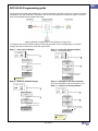
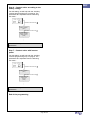
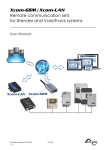
RCC-02/-03 Programming guide
This programming guide will illustrate with a concrete example. As shown in figure 9, we have a system
consisting of a 3 wire generator connected to the AC-IN of an Xtender powered by a battery. At the ACOUT of the Xtender are connected some loads.
(Figure 9) Automatic management of a 3 wire generator as energy source
To configure the various Xtender settings to start the generator at a low voltage battery or a power
outage, both with a certain time, follow the steps below :
Step 1 – User level to Expert
Step 3 – Active the Genset control
(only for a 3 wire generator)
Press SET and search with
:
Press SET and search with
User level {5012}
:
Auxiliary contacts 1
and 2 extended
functions
{1489}
Press SET and insert the code :
Press SET and search with
:
426468
Generator control
active {1491}
Press SET :
Your level is
EXPERT
i
Press SET, selection YES
with
and press SET :
Genset control
activated
The code is available in the
user manual RCC -02 / -03
Step 4 – Settings of the start contacts
Step 2 – Restore default settings
(for more information, refer to the figure 5 p.4)
Step 4.1 – Number of starting attempts
Press SET and search with
:
Press SET and search with
BASIC SETTINGS
{1100}
Press SET and search with
:
Auxiliary contacts 1
and 2 extended
functions
{1489}
:
Restore default
settings
Lockings
{1123}
{1395}
Press SET and search with
:
Number of starting
attempts
{1493}
Press SET, selection Yes
with
and press SET :
Press SET, selection the desired
number i with
and press SET :
Wait a few moment
and the system is
restored
Number of starting
attempts is set
The factory value for this
number is « 5 ». This value is
suitable for most generators.
i
Page 12 / 15
Application Note 007
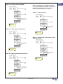
Step 4.2 – Starter pulse (with AUX2)
Press SET and search with
Step 5 – Setting of the auxiliary contact 1
:
Auxiliary contacts 1
and 2 extended
functions
{1489}
Press SET and search with
For more information and a better view of all the
programming options, refer to the “Auxiliary
contacts programming map” on page 8.
Step 5.1 – Operating mode
:
Starter pluse
duration (with AUX2)
{1492}
Press SET and search with
Press SET, selection the desired
number i with
and press SET :
:
Auxiliary contacts 1
{1201}
Time of starter pulse
is set
Press SET and search with
:
Operating mode
(AUX1)
{1202}
The factory value for this
number is « 3 seconds ». This
value is suitable for most
generators.
i
Press SET, selection the desired
setting i with
and press SET :
Time of main contact
hold/interrupt is set
Step 4.3 – Time before a starter pulse
Press SET and search with
Auxiliary contacts 1
and 2 extended
functions
{1489}
Press SET and search with
i The factory value for this setting
is « Automatic ». This setting is
necessary to drive a generator
with an Xtender.
:
:
Step 5.2 – Combination of the events for the
auxiliary contact
Time before a starter
pulse
{1494}
Press SET and search with
Press SET, selection the desired
and press SET :
number i with
Time of starter pulse
is set
:
Auxiliary contacts 1
{1201}
Press SET and search with
The factory value for this
number is « 3 seconds ». This
value is suitable for most
generators.
i
:
Combination of the
events for the
auxiliary contact
(AUX1)
{1497}
Press SET, selection the desired
and press SET :
setting i with
Step 4.4 – Main contact hold/interrupt time
Press SET and search with
Time of main contact
hold/interrupt is set
:
i The factory value for this setting
is « Any (Function OR) ». This
value is suitable for most
systems.
Auxiliary contacts 1
and 2 extended
functions
{1489}
Press SET and search with
:
Main contact
hold/interrupt time
{1574}
Press SET, selection the desired
number i with
and press SET :
Time of main contact
hold/interrupt is set
The factory value for this
number is « 0 seconds ». This
value is suitable for most
generators.
i
Page 13 / 15
Application Note 007
Step 6 – Contact active according to the
battery voltage
For this setting, we will help with the “Auxiliary
contacts programming map” on page 8. The
parameters are adjustable from the following
sub-menu :
Press SET and search with
:
Auxiliary contacts 1
{1201}
Press SET and search with
:
Contact active in
function of battery
voltage (AUX1)
{1245}
.
.
.
Note that factory values are suitable for most
generators.
Step 7 – Contact active with inverter
power
For this setting, we will help with the “Auxiliary
contacts programming map” on page 8. The
parameters are adjustable from the following
sub-menu :
Press SET and search with
:
Auxiliary contacts 1
{1201}
Press SET and search with
:
Contact active with
inverter power
(AUX1)
{1257}
.
.
.
Note that factory values are suitable for most
generators.
End of the programming
Page 14 / 15
Application Note 007
Notes
__________________________________________________________________________________
__________________________________________________________________________________
__________________________________________________________________________________
__________________________________________________________________________________
__________________________________________________________________________________
__________________________________________________________________________________
__________________________________________________________________________________
__________________________________________________________________________________
__________________________________________________________________________________
__________________________________________________________________________________
__________________________________________________________________________________
__________________________________________________________________________________
__________________________________________________________________________________
__________________________________________________________________________________
__________________________________________________________________________________
__________________________________________________________________________________
__________________________________________________________________________________
__________________________________________________________________________________
__________________________________________________________________________________
__________________________________________________________________________________
__________________________________________________________________________________
__________________________________________________________________________________
__________________________________________________________________________________
Worldwide sales and service
Switzerland
Studer Innotec SA
Rue des Casernes 57
1950 SION / Switzerland
Tel :027 205 60 80 / Fax : 027 205 60 88
Email: [email protected]
Web : http://www.studer-innotec.com
Limitation of responsibility
The use of STUDER INNOTEC SA devices is the responsibility of the customer in all cases. STUDER INNOTEC SA reserves the
right to make any modifications to the product without prior notification.
Page 15 / 15