1
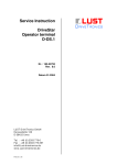
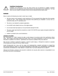
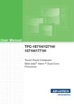
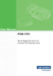
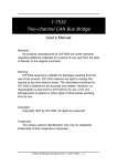
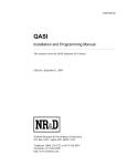
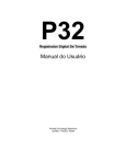
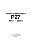
QRIO 984LL Example Manual
QRIO 984LL Example
Companion Manual
This manual provides more detail on the QRIO 984LL Video demonstrating a
Quantum PLC controlling Allen-Bradley 1771 (PLC5) I/O.
Effective: January 14, 2011
Niobrara Research & Development Corporation
P.O. Box 3418 Joplin, MO 64803 USA
Telephone: (800) 235-6723 or (417) 624-8918
Facsimile: (417) 624-8920
http://www.niobrara.com
Modicon, Square D, SY/MAX, Compact, Quantum, M340, Momentum, Premium are
trademarks of Schneider-Electric.
A-B, Allen-Bradley, ControlLogix, SLC, PLC are trademarks of Rockwell Automation.
Subject to change without notice.
© Niobrara Research & Development Corporation 2011. All Rights Reserved.
System Layout
Figure 1 System Layout
Quantum
Allen-Bradley I/O
Simulator
This demonstration video shows a simple Modicon Quantum PLC system controlling a
remote rack of Allen-Bradley 1771 Series I/O using the Niobrara QRIO-002. The
Quantum rack consists of a power supply, CPU, and the QRIO. The A-B rack consists of
an ASB, a 16-bit discrete input card, a 16-bit output card, a 16 channel analog input card,
a 4 channel analog output card, two 8-bit discrete input cards, and two 8-bit discrete
output cards. A small simulator box is also attached that provides three toggle switches
connected to inputs on the 24VDC 8-bit input cards, two 0-10Vdc potentiometers
connected to two of the analog inputs, and a DC voltmeter connected to one of the analog
outputs.
Quantum Rack
The Quantum system is a simple 3-slot rack with a CPS111 power supply in slot 1, a
CPU 213 04A in slot 2, and the QRIO-002 in slot 3. RIO Port 1 of the QRIO is
connected with the standard “Blue Hose” twin-axial cable to the A-B ASB. The standard
82 ohm terminator is installed across the clear and blue wires at the removable connector.
QRIO 984LL Example Manual
3
Figure 2 Quantum Rack
CPU 213 04
QRIO in Slot 3
Power
Supply
Clear Wire
Shield Wire
Blue Wire
Terminator
A-B Rack
The Allen-Bradley rack is an 8-slot chassis. Removing the ASB allow the examining of
the DIP switch on the rack backplane (See Figure 4). Consult the ASB user manual for
IAD
16-bit
Input
OAD
16-bit
Output
Figure 3 A-B Rack
OFE2
Analog
Output
IFE
Analog
Input
IB
8-bit
Input
OB
8-bit
Output
IB
8-bit
Input
OB
8-bit
Output
ASB
Group 0
Group 5
Group 1 Group 2 Group 3 Group 4
4
Group 7
Group 6
QRIO 984LL Example Manual
complete information about the chassis DIP switch. (The QRIO may be considered to be
the same as a PLC-5 Family, SLC, or ControlLogix scanner.) The video shows that the
chassis is configured for the following:
•
SW1 = OFF (Outputs of the chassis are deenergized when a fault is detected.)
•
SW2 = ON (Remote restart enabled)
•
SW3 = OFF (Always OFF)
•
SW4 = OFF (Always OFF)
•
SW5 = ON
•
SW6 = OFF (SW5 ON + SW6 OFF = 1-slot addressing)
•
SW7 = OFF (Always OFF)
•
SW8 = OFF (Always OFF)
Switches 5 and 6 determine the addressing of the chassis. This rack is set for 1-slot
addressing. The ASB user manual goes into great detail about ½-slot, 1-slot, and 2-slot
addressing with various 8-bit, 16-bit, and 32-bit discrete cards.
Figure 4 A-B Rack DIP Switch
SW2 = ON
SW5 = ON
All other switches
are OFF
The implication of 1-slot addressing is that every slot in the rack has 16 input bits and 16
output bits assigned. This wastes a lot of bits, but it is the only way to make it work.
Sixteen bit input only cards use all 16 input buts but waste the 16 output bits. Output
QRIO 984LL Example Manual
5
OAD
16-bit
Output
IAD
16-bit
Input
Figure 5 1-slot Bit Ranges
OFE2
Analog
Output
IFE
Analog
Input
ASB
81-96
1-16
17-32
IB
8-bit
Input
33-48
49-64
65-80
OB
8-bit
Output
IB
8-bit
Input
OB
8-bit
Output
113-128
97-112
1-slot Address assigns 16 bits IN and 16 bits OUT to every
slot. These input bits and output coils must be reserved.
cards only use the output bits and waste input bits. Eight bit cards only use the first 8 bits
of the appropriate direction. Analog cards don't use the bits at all but they still must be
assigned.
6
QRIO 984LL Example Manual
ASB Configuration
The QRIO supports ASB models of Series D and E. The ASB is configured by DIP
switches. Consult the ASB user manual for complete information about the settings and
consider the QRIO as a PLC-5, SLC, or ControlLogix Scanner.
NOTE: The ASB user manual table 2.C shows the Rack # in Octal. The settings shown
in Figure 6 are octal 12 = decimal 10 (8+2).
Figure 6 ASB DIP Switches
Switches 1&2
Set the baud rate
1ON, 2OFF = 57.6Kbps
Switches 1-6 set the
Rack Number in binary.
Switches 3 and 5 OFF
Corresponds to Rack = 10.
QRIO 984LL Example Manual
Switches 7&8
Set the 1st Group
Number = 0
7
Figure 7 ASB Blue Hose Wiring
Blue Wire
Terminator
Shield Wire
Clear Wire
The wiring of the ASB card simply connects the “Blue Hose” cable to the proper screw
terminals. Also notice that since this is the last node on the network the 82ohm
terminator is also installed across the clear and blue wires.
1771-IAD (16-bit 120VAC Discrete Input Card)
Slot 0 holds a 16-bit discrete input card. It is difficult to see in the video, but three of the
inputs on this card are hard-wired ON to 120VAC. Inputs 00, 15, and 17 (octal) are all
ON. These inputs are not used in the sample ladder logic in the Quantum, but are there
simply to assist the understanding of the bit mapping from the A-B system to the
Modicon.
The QRIO's I/O Scanner maps these 16 inputs into bits 1x0001 through 1x00016.
NOTE: The A-B rack is configured for 1-slot addressing. This means that this slot
consumes 16-1x input bits and 16-0x output coils. Therefore, coils 0x00001 through
0x000016 are assigned to this slot and may not be used elsewhere in the PLC program.
8
QRIO 984LL Example Manual
Quantum
Address
Card
Input
(octal)
Notes
1x00001
00
Wired always ON
1x00002
01
1x00003
02
1x00004
03
1x00005
04
1x00006
05
1x00007
06
1x00008
07
1x00009
10
1x00010
11
1x00011
12
1x00012
13
1x00013
14
1x00014
15
1x00015
16
1x00016
17
Wired always ON
Wired always ON
Table 1: 1771-IAD Mapping
1771-OAD (16-bit 120VAC Discrete Output Card)
Slot 1 holds a 16-bit discrete output card. Two of the outputs are controlled in the
Quantum's ladder logic. Careful viewing of the video will show switch 3 changing the
state of this card's Outputs 00 and 16 (octal) (Modicon coils 0x00017 and 0x00031).
The QRIO's I/O Scanner maps these 1 He6 outputs to coils 0x00017 through 0x00032.
NOTE: The A-B rack is configured for 1-slot addressing. This means that this slot
consumes 16 0x coils as well as 16 1x input bits. These 1x bits will always be set to zero
by the QRIO.
QRIO 984LL Example Manual
9
Quantum
Address
Card
Output
(octal)
Notes
0x00017
00
Tied to Toggle Switch #3
0x00018
01
0x00019
02
0x00020
03
0x00021
04
0x00022
05
0x00023
06
0x00024
07
0x00025
10
0x00026
11
0x00027
12
0x00028
13
0x00029
14
0x00030
15
0x00031
16
0x00032
17
Tied to Toggle Switch #3
Table 2: 1771-OAD Mapping
1771-OFE2 (12-bit 4-channel Analog Output Card)
Slot 2 contains a 4-channel analog output card. This card is configured (internal jumpers)
for 0-10VDC outputs. Output channel 1 is wired directly to the analog voltmeter. Output
channels 2, 3, and 4 are not used in this example.
The 1-slot addressing of the A-B chassis ends up mapping discrete inputs 1x00033
through 1x00048 and outputs 0x00033 through 0x00048 to this card. These bits and coils
are not used within the Quantum's ladder logic but their reservation is required.
Allen-Bradley systems control this card with a function called a block transfer write. The
QRIO uses the standard Modicon MSTR function to achieve control. The MSTR
requires two blocks of Holding Registers (4x), one for the control block, and one for the
data to be written to the analog output card.
The ladder logic used to control the MSTR to write the data is shown on page 26. The
control and data blocks are shown below:
10
QRIO 984LL Example Manual
Quantum Value
Address (hex)
Value
(decimal)
Notes
4x0100
0001
1
1=MSTR Write Command
4x0101
0000
0
Error Code Returned by QRIO
4x0102
000D
13
13 words of data in the write
4x0103
0000
0
Always 0
4x0104
0301
769
High byte = QRIO Slot Number (3)
Low byte = QRIO Port Number (1)
4x0105
000A
10
Logical Rack number of Write (10)
4x0106
0000
0
Interface Group Number of Target (0)
4x0107
0002
2
ASB Group Number of Target (2)
4x0108
0000
0
Always 0 for 1-slot addressing
Table 3: Analog Output MSTR Control Block
NOTE: The scaling for channel 1 was set to match the scaling of the analog input #1 so a
simple ADD16 could be used to copy the analog input 1 to analog output 1.
NOTE: For more information about the data block written to the OFE, consult the OFE
user manual.
Quantum Value
Value
Notes
Address (hex) (decimal)
4x0120
0669
1641
Channel 1 Data Value
4x0121
07D0
2000
Channel 2 Data Value
4x0122
07D0
2000
Channel 3 Data Value
4x0123
07D0
2000
Channel 4 Data Value
4x0124
8000
32768
Integer Data, positive scales, positive data
4x0125
0000
0
Channel 1 Min. Scale Value
4x0126
0FFF
4095
Channel 1 Max. Scale Value
4x0127
0000
0
Channel 2 Min. Scale Value
4x0128
0FFF
4095
Channel 2 Max. Scale Value
4x0129
0000
0
Channel 3 Min. Scale Value
4x0130
0FFF
4095
Channel 3 Max. Scale Value
4x0131
0000
0
Channel 4 Min. Scale Value
4x0132
0FFF
4095
Channel 4 Max. Scale Value
Table 4: Analog Output MSTR Data Block
QRIO 984LL Example Manual
11
1771-IFE (12-bit 16-channel Analog Input Card)
Slot 3 contains a 16-channel analog input card. This card is configured for -10 to
+10VDC inputs. Input channel 1 is wired directly to potentiometer #1 which provides a
0-10VDC input. Input channel 16 is wired to potentiometer #2 which also provides a 010VDC input. Input channels 2 through 15 are floating.
Channel 1 is scaled to achieve a 0-4095 value for the 0-10VDC range. This range was
chosen to allow a simple ADD16 command to copy the data from this analog input to the
analog output card. Just for fun, Channel 16 is scaled to achieve a 0-1000 value for the 010VDC range.
The 1-slot addressing of the A-B chassis ends up mapping discrete inputs 1x00049
through 1x00064 and outputs 0x00049 through 0x00064 to this card. These bits and coils
are not used within the Quantum's ladder logic but their reservation is required.
Allen-Bradley systems control this card using both a block transfer read and write. The
QRIO uses the standard Modicon MSTR functions to achieve control. Each MSTR
requires two blocks of Holding Registers (4x), one for the control block, and one for the
data to be read from the card or the setup data written to the card.
This card needs to be configured each time power is cycled on the A-B rack. Fortunately,
the card gives a status bit that may be used to trigger the configuration write. The NOBT
block in Network 5 of the 984LL program is this trigger.
The ladder logic used to control the MSTR to read the data is shown on page 27. The
control and data blocks are shown below:
Quantum Value
Address (hex)
Value
(decimal)
Notes
4x0200
0002
2
2=MSTR Read Command
4x0201
0000
0
Error Code Returned by QRIO
4x0202
0014
20
20 words of data in the read
4x0203
0000
0
Always 0
4x0204
0301
769
High byte = QRIO Slot Number (3)
Low byte = QRIO Port Number (1)
4x0205
000A
10
Logical Rack number of Write (10)
4x0206
0000
0
Interface Group Number of Target (0)
4x0207
0003
3
ASB Group Number of Target (3)
4x0208
0000
0
Always 0 for 1-slot addressing
Table 5: Analog Input READ MSTR Control Block
NOTE: For more information about the data block read from the IFE, consult the IFE
user manual.
12
QRIO 984LL Example Manual
Quantum Value
Address (hex)
Value
(decimal)
Notes
4x0220
0002
2
Diagnostics Bits (data out of range)
4x0221
0000
0
Underrange Bitmap
4x0222
8000
-32768
Overrange Bitmap
4x0223
7FFF
32750
Data Polarity Bitmap
4x0224
05E7
1511
Channel 1 Data
4x0225
FDED
-531
Channel 2 Data
4x0226
FE6C
-404
Channel 3 Data
4x0227
FECB
-309
Channel 4 Data
4x0228
0345
837
Channel 5 Data
4x0229
FD4F
-689
Channel 6 Data
4x0230
FE6C
-404
Channel 7 Data
4x0231
FE5E
-418
Channel 8 Data
4x0232
FEC7
-313
Channel 9 Data
4x0233
FE60
-416
Channel 10 Data
4x0234
FE6A
-406
Channel 11 Data
4x0235
FED1
-303
Channel 12 Data
4x0236
FD9D
-611
Channel 13 Data
4x0237
FD9F
-609
Channel 14 Data
4x0238
FE9C
-356
Channel 15 Data
4x0239
03E8
1000
Channel 16 Data
Table 6: Analog Input READ MSTR Data Block
The ladder logic used to control the MSTR to read the data is shown on page 28. The
control and data blocks are shown below:
QRIO 984LL Example Manual
13
Quantum Value
Address (hex)
Value
(decimal)
Notes
4x0300
0001
1
1=MSTR Write Command
4x0301
0000
0
Error Code Returned by QRIO
4x0302
0025
37
37 words of data in the write
4x0303
0000
0
Always 0
4x0304
0301
769
High byte = QRIO Slot Number (3)
Low byte = QRIO Port Number (1)
4x0305
000A
10
Logical Rack number of Write (10)
4x0306
0000
0
Interface Group Number of Target (0)
4x0307
0003
3
ASB Group Number of Target (3)
4x0308
0000
0
Always 0 for 1-slot addressing
Table 7: Analog Input WRITE MSTR Control Block
NOTE: For more information about the data block read from the IFE, consult the IFE
user manual.
NOTE: The IFE requires the scale values to be entered in BCD (hex) instead of decimal.
The range for input 1 is set for -4095 to +4095 for -10 to +10VDC inputs. This gives a
range of 0 to 4095 for a 0-10VDC input.
14
QRIO 984LL Example Manual
Quantum Value
Address (hex)
Value
(decimal)
Notes
4x0320
FFFF
-1
Range Selection Channels 1 to 8
4x0321
FFFF
-1
Range Selection Channels 9 to 16
4x0322
0400
1024
Data Format = Two's Complement
Range = 0 to +10V
4x0323
FFFF
-1
Sign Bits, Min. Scaling
4x0324
0000
0
Sign Bits, Max. Scaling
4x0325
4095
16533
Channel 1 Min. Scaling
4x0326
4095
16533
Channel 1 Max. Scaling
4x0327
4095
16533
Channel 2 Min. Scaling
4x0328
4095
16533
Channel 2 Max. Scaling
4x0329
4095
16533
Channel 3 Min. Scaling
4x0330
4095
16533
Channel 3 Max. Scaling
4x0331
4095
16533
Channel 4 Min. Scaling
4x0332
4095
16533
Channel 4 Max. Scaling
4x0333
4095
16533
Channel 5 Min. Scaling
4x0334
4095
16533
Channel 5 Max. Scaling
4x0335
4095
16533
Channel 6 Min. Scaling
4x0336
4095
16533
Channel 6 Max. Scaling
4x0337
4095
16533
Channel 7 Min. Scaling
4x0338
4095
16533
Channel 7 Max. Scaling
4x0339
4095
16533
Channel 8 Min. Scaling
4x0340
4095
16533
Channel 8 Max. Scaling
4x0341
4095
16533
Channel 9 Min. Scaling
4x0342
4095
16533
Channel 8 Max. Scaling
4x0343
4095
16533
Channel 10 Min. Scaling
4x0344
4095
16533
Channel 10 Max. Scaling
4x0345
4095
16533
Channel 11 Min. Scaling
4x0346
4095
16533
Channel 11 Max. Scaling
4x0347
4095
16533
Channel 12 Min. Scaling
4x0348
4095
16533
Channel 12 Max. Scaling
QRIO 984LL Example Manual
15
4x0349
4095
16533
Channel 13 Min. Scaling
4x0350
4095
16533
Channel 13 Max. Scaling
4x0351
4095
16533
Channel 14 Min. Scaling
4x0352
4095
16533
Channel 14 Max. Scaling
4x0353
4095
16533
Channel 15 Min. Scaling
4x0354
4095
16533
Channel 15 Max. Scaling
4x0355
1000
4096
Channel 16 Min. Scaling
4x0356
1000
4096
Channel 16 Max. Scaling
Table 8: Analog Input READ MSTR Data Block
1771-IB (8-bit 24VDC Discrete Input Cards)
Slots 4 and 5 contain 8-bit 24VDC input cards. Each card is assigned 16 bits in and out
but only the first 8 input bits are used.
Quantum
Address
Card Input
(octal)
Notes
1x00065
00
Toggle Switch #1
1x00066
01
1x00067
02
1x00068
03
1x00069
04
1x00070
05
1x00071
06
1x00072
07
Toggle Switch #2
1x00073
Not Used
1x00074
Not Used
1x00075
Not Used
1x00076
Not Used
1x00077
Not Used
1x00078
Not Used
1x00079
Not Used
1x00080
Not Used
Table 9: 1771-IB Slot 4 Mapping
16
QRIO 984LL Example Manual
Quantum
Address
Card Input
(octal)
Notes
1x00081
00
Toggle Switch #3
1x00082
01
1x00083
02
1x00084
03
1x00085
04
1x00086
05
1x00087
06
1x00088
07
1x00089
Not Used
1x00090
Not Used
1x00091
Not Used
1x00092
Not Used
1x00093
Not Used
1x00094
Not Used
1x00095
Not Used
1x00096
Not Used
Table 10: 1771-IB Slot 5 Mapping
1771-OB (8-bit 24VDC Discrete Output Cards)
Slots 6 and 7 contain 8-bit 24VDC output cards. Each card is assigned 16 bits in and out
but only the first 8 output bits are used.
QRIO 984LL Example Manual
17
Quantum
Address
Card Input
(octal)
Notes
1x00097
00
Tied to Toggle Switch #1
1x00098
01
Not of Toggle Switch #2
1x00099
02
1x00100
03
1x00101
04
1x00102
05
1x00103
06
1x00104
07
1x00105
Not Used
1x00106
Not Used
1x00107
Not Used
1x00108
Not Used
1x00109
Not Used
1x00110
Not Used
1x00111
Not Used
1x00112
Not Used
Table 11: 1771-OB Slot 6 Mapping
18
QRIO 984LL Example Manual
Quantum
Address
Card Input
(octal)
Notes
1x00113
00
Tied to Toggle Switch #3
1x00114
01
Tied to Toggle Switch #3
1x00115
02
Tied to Toggle Switch #3
1x00116
03
1x00117
04
1x00118
05
1x00119
06
1x00120
07
1x00121
Not Used
1x00122
Not Used
1x00123
Not Used
1x00124
Not Used
1x00125
Not Used
1x00126
Not Used
1x00127
Not Used
1x00128
Not Used
Table 12: 1771-OB Slot 7 Mapping
Simulator Box
QRIO 984LL Example Manual
19
The Simulator box attached to the A-B chassis has three toggle switches wired to the
24VDC input cards, two 0-10VDC potentiometers wired to the analog input card, and a
0-10VDC voltmeter wired to the analog output card.
Figure 8 Simulator
Switch 1
Slot 4
Input 00
Pot 1
Analog IN #1
20
Switch 2
Slot 4
Input 07
Switch 3
Slot 5
Input 00
Voltmeter
Analog OUT #1
Pot 2
Analog IN #16
QRIO 984LL Example Manual
ProWORX 32 Configuration
The configuration of the Quantum PLC is very simple. The only card in the traffic cop is
the QRIO in slot 3. The QRIO pretends to be an NOE-771-00 network card and uses the
I/O Scanner config extensions of the NOE to define its operation.
Figure 9: Traffic Cop
The I/O Scanner defines where the discrete data from the remote rack is placed within the
Quantum. In this case, the inputs are placed into 8 words starting at 1x00001 and the
outputs are placed into 8 words starting at 0x00001.
The A-B chassis is set to 1-slot addressing so each slot gets 16 bits of both 1x bits and 0x
coils.
QRIO 984LL Example Manual
21
Figure 10: I/O Scanner
IP Address: The “Local Device” IP Address set the baud rates for QRIO ports 1 and 2.
The decimal value of 1 in the first and third octets sets the baud rates of both ports to
57.6kbaud.
Health Block: The QRIO provides the normal 128 bit health block of an NOE's I/O
Scanner. Each bit in the health block is set true if the I/O Scanner entry is successful.
Slot Number: This defines the Quantum rack slot number of the QRIO.
IP Address: The “Remote Device” IP Address sets the QRIO port number (1), target
remote rack (10), starting group number (0), and word length (8).
The Unit ID, Repetition, and Health Timeout are ignored and may be left at 0.
This rack requires both inputs and outputs so the Read/Write function is selected.
The Fallback value may be set to Zero or Hold Last for the inputs to the Quantum.
The “Read From Remote To” field sets the starting location in the Quantum CPU for the
discrete inputs from the remote rack. Selecting 1x bits allows for simple ladder logic
sections. The “From” and “Length” fields are set to 4000001 and the length of the data
segment (8 words).
The “Write To Remote From” field sets the starting location in the Quantum CPU for the
discrete outputs. Selecting 0x coils simplifies the ladder logic segments. The “To” field
22
QRIO 984LL Example Manual
is always set to 400001. The “Length” field should be set to the word size (8).
In this example, the 8 words of input bits m 1x0001 through 1x0128 are used by the
QRIO. Output coils 0x0001 through 0x0128 are also reserved by the QRIO. Table 13
gives an overview of the bits and coils assigned to actual inputs and outputs.
I/O
Label
Slot
0
Slot
1
Slot
2
Slot
3
Slot
4
Slot
5
Slot
6
Slot
7
(octal)
16-bit
In
16-Bit
Out
Analog
Out
Analog
In
8-bit
In
8-bit
In
8-bit
Out
8-bit
Out
00
1x1
0x17
1x65
1x81
0x97
0x113
01
1x2
0x18
1x66
1x82
0x98
0x114
02
1x3
0x19
1x67
1x83
0x99
0x115
03
1x4
0x20
1x68
1x84
0x100
0x116
04
1x5
0x21
1x69
1x85
0x101
0x117
05
1x6
0x22
1x70
1x86
0x102
0x118
06
1x7
0x23
1x71
1x87
0x103
0x119
07
1x8
0x24
1x72
1x88
0x104
0x120
10
1x9
0x25
11
1x10
0x26
12
1x11
0x27
13
1x12
0x28
14
1x13
0x29
15
1x14
0x30
16
1x15
0x31
17
1x16
0x32
Table 13: Bit and Coil Usage
QRIO 984LL Example Manual
23
Figure 11: Simple Logic
Network 1 is some simple associations of outputs to the three input toggle switches. You
can see the output lights change state on the video as the switches are moved.
24
QRIO 984LL Example Manual
Figure 12: Copy Analog IN 1 Value to Analog OUT 1
Network 2 simply uses the ADD16 to copy the analog input #1 data (register 4x224) to
the analog output #1 data (register 4x120).
QRIO 984LL Example Manual
25
Figure 13: Analog OUT Write MSTR
Network 3 has the trigger timer for the analog out write and analog in read MSTRs. It
also includes the analog out write MSTR. Note that the MSTR is latched on until it is
successful (0x513) or errors (0x512).
26
QRIO 984LL Example Manual
Figure 14: Analog IN Read MSTR
Network 4 is the analog in read MSTR.
QRIO 984LL Example Manual
27
Figure 15: Analog IN Write MSTR
Network 4 is the configuration write MSTR for the analog input card. It is triggered on
the first scan after loading the program from ProWORX32 (coil 0x501) and also
triggered when the analog input card is unconfigured (bit 16 of 4x220).
28
QRIO 984LL Example Manual