1
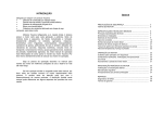
QASI Manual
QASI
Installation and Programming Manual
This manual covers the QASI Quantum AS-i master.
Effective: September 3, 2009
Niobrara Research & Development Corporation
P.O. Box 3418 Joplin, MO 64803 USA
Telephone: (800) 235-6723 or (417) 624-8918
Facsimile: (417) 624-8920
http://www.niobrara.com
Modicon, Square D, SY/MAX, Compact, Quantum, M340, Momentum, Premium are
trademarks of Schneider-Electric.
Subject to change without notice.
© Niobrara Research & Development Corporation 2009. All Rights Reserved.
Contents
1 Introduction.................................................................................................7
2 Installation...................................................................................................9
Module Installation.................................................................................9
Software Installation...............................................................................9
ProWORX32 Configuration.............................................................10
Concept 2.6 Configuration................................................................11
Unity Pro Configuration...................................................................12
Power Supply........................................................................................13
RS-232 Serial Port................................................................................13
Updating the QASI Firmware...............................................................15
3 AS-i 3.0 Operation.....................................................................................17
Rack Inputs...........................................................................................17
Status (word 1).................................................................................19
Discrete Input Data (words 2..17)....................................................20
Input Window Data...........................................................................21
Rack Outputs.........................................................................................22
Control (word 1)...............................................................................22
Discrete Output Data (words 2..17)..................................................23
Output Window Data........................................................................25
Data Window Operation........................................................................25
Configuration Block.........................................................................25
Analog Output Block........................................................................29
Analog Input Block..........................................................................30
984LL Configuration Example.............................................................33
Unity Pro Configuration Example........................................................39
4 EIA 921 Emulation....................................................................................43
Inputs.....................................................................................................43
Input Data.........................................................................................43
List of Active Slaves.........................................................................44
List of Detected Slaves.....................................................................44
Status................................................................................................45
Outputs..................................................................................................46
AS-i Outputs.....................................................................................46
Control Word....................................................................................47
iii
5 Front Panel Operation...............................................................................48
Push Buttons.........................................................................................48
LCD Screen...........................................................................................48
Backlight...........................................................................................48
Boot Sequence Screens.....................................................................49
Operating Screens.................................................................................49
Overview..........................................................................................49
Bus Page...........................................................................................49
SLV Page..........................................................................................50
Device Configuration Page...............................................................51
Status Page........................................................................................52
Control Page.....................................................................................53
Stats Page..........................................................................................53
Mode Change........................................................................................54
Manual Slave Addressing......................................................................54
6 Register List..............................................................................................57
3x Registers......................................................................................59
4x Registers......................................................................................59
6x files..............................................................................................60
QASI Configuration Block...............................................................61
QASI Analog Outputs Block............................................................63
Qasi Analog Input Block..................................................................67
Figures
Figure 1.1: QASI Front Panel..............................................................................................7
Figure 1.2: Typical Configuration........................................................................................8
Figure 2.1: Unity Pro GEN ANA IO Configuration..........................................................12
Figure 2.2 Power Connector Diagram...............................................................................13
Figure 2.3 Serial Port Diagram..........................................................................................14
Figure 2.4.: MM1 Serial Cable..........................................................................................15
Figure 2.5: FWLOAD Screen............................................................................................16
Figure 3.1: QASIInput Structure in Unity Pro...................................................................18
Figure 3.2: Unity Pro DDT List.........................................................................................18
Figure 3.3: Rack Outputs in Unity Pro..............................................................................22
Figure 3.4: Example Configuration...................................................................................34
Figure 3.5: Configuration Block Network.........................................................................36
Figure 3.6: Analog Output Block Network........................................................................37
Figure 3.7: Analog In Block Network................................................................................38
Figure 3.8: Example Configuration...................................................................................40
Figure 3.9: Unity QASI_Exchange DFB...........................................................................41
iv
Contents
Tables
Table 2.1: RJ45 RS-232 Pinout..........................................................................................14
Table 3.1: Status Word (Input Word 1)..............................................................................19
Table 3.2: AS-i Discrete Inputs..........................................................................................20
Table 3.3: Window Input Registers....................................................................................21
Table 3.4: Control Word (Output Word 1).........................................................................23
Table 3.5: AS-i Discrete Outputs.......................................................................................24
Table 3.6: Window Output Registers (Words 18..27)........................................................25
Table 3.7: Configuration Block (PCD words 0..63)..........................................................26
Table 3.8: AS-i Permanent Parameters (words 64..79)......................................................27
Table 3.9: AS-i List of Projected Slaves (LPS)..................................................................28
Table 3.10: AS-i List of Offline Slaves (LOS)...................................................................29
Table 3.11: Analog Output Registers (Words 1..128)........................................................29
Table 3.12: Analog Input Registers (Words 1..128)...........................................................31
Table 3.13: List of Activated Slaves (LAS).......................................................................32
Table 3.14: List of Detected Slaves (LDS)........................................................................32
Table 3.15: List of Peripheral Faults (LPF).......................................................................33
Table 3.16: List of Corrupted Slaves (LCS)......................................................................33
Table 3.17: Configuration Block (non-zero values)..........................................................34
Table 3.18: Configuration Block (non-zero values)..........................................................40
Table 4.1: AS-i Bus Inputs.................................................................................................44
Table 4.2: Active Slaves (LAS).........................................................................................44
Table 4.3: Detected Slaves (LDS)......................................................................................45
Table 4.4: Status Word (Word 13)......................................................................................45
Table 4.5: AS-i Bus Outputs..............................................................................................46
Table 4.6: Control Word (Word 9).....................................................................................47
Contents
v
1
Introduction
The Niobrara QASI is a Modicon Quantum compatible module that allows the PLC
system to control a local network of AS-Interface I/O devices. The QASI is a standard
single-width I/O module that resides in any slot in any local, remote, or distributed I/O
rack.
Figure 1.1: QASI Front Panel
LCD
PAGE Button
Minus Button
Plus Button
AS-i Port
RS-232 Port
The QASI can operate in either of two different field-selectable modes: AS-i 3.0 mode
QASI Manual
7
and EIA 921 compatibility mode. The AS-i 3.0 mode supports the newer features of AS-i
version 3.0 which includes analog I/O support and 62 possible I/O devices. The EIA 921
model emulates the Schneider Electric 140 EIA 921 00 AS-i version 1.1 master. By
selecting the EIA 921 compatible mode, the user may substitute a QASI for the EIA 921
without changing the PLC configuration.
Figure 1.2: Typical Configuration
PLC
QASI
AS-I Power Supply
AS-I Slaves
Figure 1.2 shows a typical configuration where a QASI is installed in a Quantum PLC
rack. The QASI is connected to a standard AS-i power supply, and the AS-i slave I/O
connected through the standard AS-i 2-wire network.
8 Introduction 1
QASI Manual
2
Installation
Module Installation
•
Mount the QASI in any slot in the Quantum local, remote, or distributed rack.
•
Tighten the mounting screw to ensure that the card will not accidentally be
removed.
•
Connect the AS-i power supply to the QASI's removable green connector
observing proper polarity of the cable wires. Standard AS-i cables use the blue
wire for (-) and then brown wire for (+).
•
Connect the AS-i power supply to the AS-i daisy chain.
•
Proceed to Chapter for more information about configuration.
Software Installation
The QASI_SETUP.EXE file includes this user manual, the QASI.fwl firmware file, the
FWLOAD.EXE firmware loader utility, the NRDTOOL.EXE register viewer utility, the
Schneider Alliance file for ProWORX32, and a useful DFB for operating the QASI in
Unity Pro. The latest version of this file is located at www.niobrara.com. Follow the link
for “Download Area”, select “QASI”.
QASI Manual
9
ProWORX32 Configuration
The Schneider Alliances tool in ProWORX32 is used to add the QASI to a Quantum
system by using the following instructions:
1. Close an open copy of ProWORX32.
2. Select Start, Programs, ProWORX32, Schneider Alliances.
3. Select the “Import...” button.
4. Select “OK” to “Prompt to overwrite existing modules”.
5. Browse to C:\Niobrara\QASI\ and select “Niobrara_QASI.SAF” then select
“Open”.
6. Select “OK” for Import Completed Successfully.
7. Close the Schneider Alliances tool.
The QASI is now added to ProWORX32.
10 Installation 2
QASI Manual
Concept 2.6 Configuration
The Niobrara MDC file is used with the “Modconnect Tool” in Concept to add the QASI
into the Concept programming environment. Install CONCEPT26_SETUP.EXE from
the Niobrara CD or from the www.niobrara.com then follow these instructions:
1. Close Concept.
2. Select Start, Programs, Concept, Modconnect Tool.
3. Select File, Open Installation File.
4. Browse to C:\Niobrara\CONCPT26\ and select the file NRD_2_6.MDC.
5. Select the line MDC-QASI.
6. Select “Add”.
7. Select “File, Save Changes”
8. Select “File, Exit”
The QASI is now ready for use within Concept.
QASI Manual
2 Installation 11
Unity Pro Configuration
The QASI is used as a GEN ANA IO card in Unity Pro as shown in Figure 2.1: Unity Pro
GEN ANA IO Configuration. The QASI will use 27 words of %IW and 27 words of
%MW for the I/O. The “Configuration registers” are not used.
Figure 2.1: Unity Pro GEN ANA IO Configuration
A Derived Function Block named QASI_Exchange is included in the \Niobrara\QASI\
folder. This DFB may be imported into Unity Pro 4.1 from inside a project by right
clicking on the “Derived FB Types” structure and selecting “Import”.
This DFB will include a number of Derived Data Types that all start with QASI (see
Figure 3.2: Unity Pro DDT List). Several of these DDTs are used internally within the
QASI_Exchange DFB and all start with QASI_IS_. The DDTs of interest to the
programmer are described in the next chapter and include:
12 Installation 2
QASI Manual
•
QASIInput – the 27 words of rack Input
•
QASIOutput – the 27 words of rack output
•
QASIConfig – the structure that defines the attached AS-i slaves and their
configuration parameters.
•
QASIAnalogIn – the structure that provides all of the possible AS-i analog input
values as well as the status bitmaps of the AS-i network.
•
QASIAnalogOut – the structure that determines all of the possible AS-i analog
output data.
Power Supply
The QASI operates on 24Vdc, which is supplied an appropriate AS-I power supply such
as the Modicon TSX Sup power supply. The QASI's removable power supply connector
pin-out is shown in Figure 2.2. The standard color code for an AS-i network is for the (-)
wire to be blue and the (+) wire to be brown. Consult the AS-i network or power supply
documentation for more information.
Figure 2.2 Power
Connector Diagram
AS-i
Channel
+
RS-232 Serial Port
The bottom port of the QASI is a standard Modicon pin out RJ45 RS-232 port. The pin
out is shown in Table 2.1: RJ45 RS-232 Pinout. The Niobrara MM1 cable is used to
connect Port 1 of the QASI is to the a standard 9-pin serial port on a PC. This connection
would rarely be used since all features of the QASI may be accessed through front panel,
or the Quantum backplane. This port may be used to load firmware into the QASI when
new firmware becomes available. It may also be used as a pass-through port for AS-i
software running on a PC. It also supports Modbus RTU communications at 19200,N,8,1
to address 255.
QASI Manual
2 Installation 13
Table 2.1: RJ45 RS-232 Pinout
Pin
Function
1
+5Vdc
2
DSR (pulled high)
3
Data TX
4
Data RX
5
Signal GND
6
RTS
7
CTS
8
Chassis GND
Figure 2.3 Serial Port Diagram
RS-232
Pin 1
14 Installation 2
QASI Manual
Figure 2.4.: MM1 Serial Cable
QASI Connection
PC Serial Port Pin
1
1
2
2
3
3
4
4
5
5
6
6
7
7
8
8
9
Updating the QASI Firmware
On occasion it may be necessary to update the operating system of the QASI. The
FWLOAD program is used to install the QASI firmware through the RS-232 serial port.
1. Remove the QASI from the Quantum rack.
2. Hold down the “Page” key while replacing the QASI in the rack. The screen on
the QASI will power up and eventually show “FIRMWARE LOADER”.
3. Start FWLOAD.EXE. The Windows Start Menu link is “Start, Programs,
Niobrara, QASI, FWLOAD QASI Firmware”.
4. Click on the Browse button and select QASI.FWL.
5. Ensure that the proper PC serial port is selected (COM1).
6. Connect the MM1 cable from the QASI port 1 to the selected PC serial port.
QASI Manual
2 Installation 15
7. Press the “Start Download” button. FWLOAD will open a progress bar to show
the status of the download.
8. Press either the + or – keys on the QASI to return to normal operation. Or, simply
cycle power on the QASI to return the unit to normal operation. The module is
ready for use.
Figure 2.5: FWLOAD Screen
16 Installation 2
QASI Manual
3
AS-i 3.0 Operation
The QASI supports AS-Interface Mode 3.0 operation. This mode supports the newer
features of AS-i including:
•
Analog I/O Slaves
•
Up to 62 discrete I/O module support with A/B addressing
•
Individual Device Alarms
Note: The QASI may operate in AS-i version 3.0 mode or 140EIA921 emulation
mode. To verify the operating mode, press the Page button until viewing the
Status page. Now press the + or – key to see the page with the F/W Version and
Mode displayed. If the QASI is in 140EIA921 emulation mode, it may be
returned to version 3.0 mode by pressing and holding both the + and – keys at the
same time for 5 seconds while the module is powered. The display will change to
show “Change Mode” and then reboot into the new mode. See section Mode
Change on page 54.
The version 3.0 AS-i network allows for many more words of I/O than may be Traffic
Copped to an individual Quantum I/O module. The QASI gets past this limitation by
implementing a “windowing” scheme to move blocks of data through the Quantum
backplane. This method requires minimal PLC programming and works in the local,
remote, and distributed I/O racks.
The QASI is listed in the Traffic Cop as an I/O module with a Module ID of 356(dec) or
0164(hex) with 27 input words and 27 output words.
Rack Inputs
The QASI in Version 3.0 mode uses 27 words of input Traffic Copped as 3x (%IW)
registers. These inputs are divided into three groups:
•
Status (word 1)
•
Discrete Inputs for Slaves 1A...31B (words 2..17)
•
Analog/Status Data Window (words 18..27)
QASI Manual
17
Figure 3.2: Unity Pro DDT List
Figure 3.1: QASIInput Structure in Unity Pro
18 AS-i 3.0 Operation 3
QASI Manual
Status (word 1)
Input word 1 provides a bitmap of the status of the module. IEC bit 0 is the least
significant bit (bit 16 in 984LL).
Table 3.1: Status Word (Input Word 1)
Bit
(IEC)
Bit
(984)
0
16
AS-I Bus Config OK
AS-I Bus Config Not OK
1
15
Slave With Address 0 Present
Slave With Address 0 Not Present
2
14
Automatic Address Available
Automatic Address Not Available
3
13
Automatic Addressing Possible Automatic Addressing Impossible
4
12
Protected Mode
Configuration Mode
5
11
Normal Operation Active
Normal Operation Inactive
6
10
AS-i Power Failure
AS-i Power Normal
7
9
AS-i Bus in Offline mode
AS-i Bus Not in Offline mode
8
8
Peripheral Error Active
No Peripheral Errors
9
7
Not Used
Not Used
10
6
Not Used
Not Used
11
5
Not Used
Not Used
12
4
Not Used
Not Used
13
3
Not Used
Not Used
14
2
Not Used
Not Used
15
1
QASI has been configured
QASI is not configured
QASI Manual
Meaning When On
Meaning When Off
3 AS-i 3.0 Operation 19
Discrete Input Data (words 2..17)
Input Words 1 through 16 provide the discrete data bits for the 62 possible AS-i slaves.
Each slave has four possible AS-i inputs D0...D3. If the AS-i input is ON then the
corresponding PLC input bit will be turned ON.
NOTE: Slaves that do not support extended A/B addressing are always configured as an
“A” slave address.
EXAMPLE: Slave 4A has Input D0=1, D1=0, D2=1, and D3=0. Slave 5A has all four
inputs OFF (0). Slave 6A has all four inputs ON (1). Slave 7A has input D0=1 and
inputs D1, D2, and D3 = 0. Rack Input word 3 would have the value 1F05 (hex) = 7941
(dec).
Table 3.2: AS-i Discrete Inputs
Distribution
MSB
LSB
Word Bit (IEC)
15 14 13 12 11 10 9
8
7
6
Word Bit (984)
1
8
9
10 11 12 13 14 15 16
Slave Input
D3 D2 D1 D0 D3 D2 D1 D0 D3 D2 D1 D0 D3 D2 D1 D0
2
3
4
5
6
7
5
4
3
2
1
0
Word 2
Slave 3A
Slave 2A
Slave 1A
Unused
Word 3
Slave 7A
Slave 6A
Slave 5A
Slave 4A
Word 4
Slave 11A
Slave 10A
Slave 9A
Slave 8A
Word 5
Slave 15A
Slave 14A
Slave 13A
Slave 12A
Word 6
Slave 19A
Slave 18A
Slave 17A
Slave 16A
Word 7
Slave 23A
Slave 22A
Slave 21A
Slave 20A
Word 8
Slave 27A
Slave 26A
Slave 25A
Slave 24A
Word 9
Slave 31A
Slave 30A
Slave 29A
Slave 28A
Word 10
Slave 3B
Slave 2B
Slave 1B
Unused
Word 11
Slave 7B
Slave 6B
Slave 5B
Slave 4B
Word 12
Slave 11B
Slave 10B
Slave 9B
Slave 8B
Word 13
Slave 15B
Slave 14B
Slave 13B
Slave 12B
Word 14
Slave 19B
Slave 18B
Slave 17B
Slave 16B
Word 15
Slave 23B
Slave 22B
Slave 21B
Slave 20B
Word 16
Slave 27B
Slave 26B
Slave 25B
Slave 24B
Word 17
Slave 31B
Slave 30B
Slave 29B
Slave 28B
20 AS-i 3.0 Operation 3
QASI Manual
Input Window Data
The Input Window data is normally only accessed through the TBLK block in 984LL or
with the QASI_Exchange DFB in Unity Pro.
Table 3.3: Window Input Registers
Register
Description
Word 18
Output Page Select
Word 19
Input Page Select
Word 20
Input Page Data word 0
Word 21
Input Page Data word 1
Word 22
Input Page Data word 2
Word 23
Input Page Data word 3
Word 24
Input Page Data word 4
Word 25
Input Page Data word 5
Word 26
Input Page Data word 6
Word 27
Input Page Data word 7
QASI Manual
3 AS-i 3.0 Operation 21
Rack Outputs
The QASI in Version 3.0 mode uses 27 words of outputs Traffic Copped as 4x (%MW)
registers. These Outputs are divided into three groups:
•
Control (word 1)
•
Discrete Outputs for Slaves 1A...31B (words 2..17)
•
Analog/Control Data Window (words 18..27)
Figure 3.3: Rack Outputs in Unity Pro
Control (word 1)
Output word 1 provides a bitmap of the control of the module. IEC bit 0 is the least
significant bit (bit 16 in 984LL).
22 AS-i 3.0 Operation 3
QASI Manual
Table 3.4: Control Word (Output Word 1)
Bit
(IEC)
Bit
(984)
Meaning When On
Meaning When Off
0
16
Not Used
1
15
Set Offline AS-i mode
2
14
Set Data Exchange active
3
13
Set Configuration Mode
4
12
Disable Auto Address Assignment
5
11
Enable Global LOS
6
10
Not Used
7
9
Not Used
8
8
Not Used
9
7
Not Used
10
6
Not Used
11
5
Not Used
12
4
Not Used
13
3
Not Used
14
2
Not Used
15
1
Trigger QASI to re-read configuration block
Set Protected Mode
Normal Operation
The trigger QASI to re-read configuration block bit (bit 15) corrupts the currently stored
configuration on the falling edge. This clears the Status word bit 15 (IEC) which forces
the PLC logic to load the Configuration Block into the QASI.
Discrete Output Data (words 2..17)
Input Words 1 through 16 provide the discrete data bits for the 62 possible AS-i slaves.
Each slave has four possible AS-i outputs D0...D3. If the PLC output bit is ON then the
corresponding AS-i output bit will be turned ON.
EXAMPLE: Slaves 27B, 26B, and 25B are commanded to have all outputs OFF (0) while
Slave 24B has outputs D1 and D2 ON (1) with D0 and D3 OFF (0). Rack Output word
16 would have the value 0007 (hex) = 7 (dec).
QASI Manual
3 AS-i 3.0 Operation 23
Table 3.5: AS-i Discrete Outputs
Distribution
MSB
LSB
Word Bit (IEC)
15 14 13 12 11 10 9
8
7
6
Word Bit (984)
1
8
9
10 11 12 13 14 15 16
Slave Output
D3 D2 D1 D0 D3 D2 D1 D0 D3 D2 D1 D0 D3 D2 D1 D0
2
3
4
5
6
7
5
4
3
2
1
0
Word 2
Slave 3A
Slave 2A
Slave 1A
Unused
Word 3
Slave 7A
Slave 6A
Slave 5A
Slave 4A
Word 4
Slave 11A
Slave 10A
Slave 9A
Slave 8A
Word 5
Slave 15A
Slave 14A
Slave 13A
Slave 12A
Word 6
Slave 19A
Slave 18A
Slave 17A
Slave 16A
Word 7
Slave 23A
Slave 22A
Slave 21A
Slave 20A
Word 8
Slave 27A
Slave 26A
Slave 25A
Slave 24A
Word 9
Slave 31A
Slave 30A
Slave 29A
Slave 28A
Word 10
Slave 3B
Slave 2B
Slave 1B
Unused
Word 11
Slave 7B
Slave 6B
Slave 5B
Slave 4B
Word 12
Slave 11B
Slave 10B
Slave 9B
Slave 8B
Word 13
Slave 15B
Slave 14B
Slave 13B
Slave 12B
Word 14
Slave 19B
Slave 18B
Slave 17B
Slave 16B
Word 15
Slave 23B
Slave 22B
Slave 21B
Slave 20B
Word 16
Slave 27B
Slave 26B
Slave 25B
Slave 24B
Word 17
Slave 31B
Slave 30B
Slave 29B
Slave 28B
24 AS-i 3.0 Operation 3
QASI Manual
Output Window Data
The Output Window Data is normally only accessed through the TBLK block in 984LL
or with the QASI_Exchange DFB in Unity Pro.
Table 3.6: Window Output Registers (Words 18..27)
Register
Description
Word 18
Input Page Ack
Word 19
Output Page Ack
Word 20
Output Page Data word 0
Word 21
Output Page Data word 1
Word 22
Output Page Data word 2
Word 23
Output Page Data word 3
Word 24
Output Page Data word 4
Word 25
Output Page Data word 5
Word 26
Output Page Data word 6
Word 27
Output Page Data word 7
Data Window Operation
The data windows reserved in the rack input and output words are used to pass 8 words
of data in and 8 words of data out through the backplane on every PLC scan. Three
simple 984LL networks with a few TBLK, BLKM, and AD16 elements (or a DFB in
Unity Pro) are all that is needed to configure the QASI and move all possible analog data
to/from the PLC to the AS-i network.
Three data structures are required within the PLC for normal AS-i Version 3.0 operation
of the QASI:
•
Configuration Block
•
Analog Output Data
•
Analog Input Data/Operation Status
Configuration Block
The Configuration Block consists of 88 words with the first 64 used to set the Permanent
Configuration Data (PCD) for each of the possible slaves. The PCD value includes the
I/O configuration nybble, IO Code nybble, Extended ID1 code nybble, and ID2 code
QASI Manual
3 AS-i 3.0 Operation 25
nybble. These values are used as the expected configuration in the protected mode.
NOTE: Slaves that do not support the extended profile ID2 must have the hex value F
loaded into the PCD.
EXAMPLE: Slave 2A is a Telemecanique ASI 20MT414OS 4in/4out discrete module.
This module has a AS-i profile of 7.0.E where IO Code = 7, ID code = 0, ID1 = E, and
ID2 = F. The value loaded into Control Block word 2 should be 70EF (hex) = 28911
(dec).
EXAMPLE: Slave 10A is a Bihl+Wiedemann 2 channel analog output card with a profile
of 7.3 with the IO Code = 7, ID Code = 3, default ID1 code = F, and ID2 code = 5. The
value loaded into Control Block word 10 should be 73F5 (hex) = 29685 (dec).
Table 3.7: Configuration Block (PCD words 0..63)
Word
Description
Word
Description
0
Not Used
32
Not Used
1
Perm. Config. Data 1A
33
Perm. Config. Data 1B
2
PCD 2A
34
PCD 2B
3
PCD 3A
35
PCD 3B
4
PCD 4A
36
PCD 4B
5
PCD 5A
37
PCD 5B
6
PCD 6A
38
PCD 6B
7
PCD 7A
39
PCD 7B
8
PCD 8A
40
PCD 8B
9
PCD 9A
41
PCD 9B
10
PCD 10A
42
PCD 10B
11
PCD 11A
43
PCD 11B
12
PCD 12A
44
PCD 12B
13
PCD 13A
45
PCD 13B
14
PCD 14A
46
PCD 14B
15
PCD 15A
47
PCD 15B
16
PCD 16A
48
PCD 16B
17
PCD 17A
49
PCD 17B
18
PCD 18A
50
PCD 18B
19
PCD 19A
51
PCD 19B
20
PCD 20A
52
PCD 20B
26 AS-i 3.0 Operation 3
QASI Manual
Word
Description
Word
Description
21
PCD 21A
53
PCD 21B
22
PCD 22A
54
PCD 22B
23
PCD 23A
55
PCD 23B
24
PCD 24A
56
PCD 24B
25
PCD 25A
57
PCD 25B
26
PCD 26A
58
PCD 26B
27
PCD 27A
59
PCD 27B
28
PCD 28A
60
PCD 28B
29
PCD 29A
61
PCD 29B
30
PCD 30A
62
PCD 30B
31
PCD 31A
63
PCD 31B
Words 64 though 79 of the Control Block set the Permanent Parameters of each AS-i
slave. Each slave has four bits of Permanent Parameters available for use. Refer to the
slave's documentation for the description of these parameters.
EXAMPLE: Slave 10A is a 2 channel analog output card where P0=0 (means P1 and P3
determine the operating mode of ch1 and ch2), P1=0 (ch1 in voltage mode), P2=1
(peripheral fault is indicated on a broken wire), and P3=1 (ch2 in current mode). If
slaves 8A, 9A, and 11A all have their parameters set to 0 then word 66 would have the
value 00C0 (hex) = 192 (dec).
Table 3.8: AS-i Permanent Parameters (words 64..79)
Word
MSB
LSB
Word Bit (IEC)
15 14 13 12 11 10 9
8
7
6
Word Bit (984)
1
8
9
10 11 12 13 14 15 16
Parameters
P3 P2 P1 P0 P3 P2 P1 P0 P3 P2 P1 P0 P3 P2 P1 P0
2
3
4
5
6
7
5
4
3
2
1
0
64
Slave 3A
Slave 2A
Slave 1A
Unused
65
Slave 7A
Slave 6A
Slave 5A
Slave 4A
66
Slave 11A
Slave 10A
Slave 9A
Slave 8A
67
Slave 15A
Slave 14A
Slave 13A
Slave 12A
68
Slave 19A
Slave 18A
Slave 17A
Slave 16A
69
Slave 23A
Slave 22A
Slave 21A
Slave 20A
QASI Manual
3 AS-i 3.0 Operation 27
Word
MSB
LSB
70
Slave 27A
Slave 26A
Slave 25A
Slave 24A
71
Slave 31A
Slave 30A
Slave 29A
Slave 28A
72
Slave 3B
Slave 2B
Slave 1B
Unused
73
Slave 7B
Slave 6B
Slave 5B
Slave 4B
74
Slave 11B
Slave 10B
Slave 9B
Slave 8B
75
Slave 15B
Slave 14B
Slave 13B
Slave 12B
76
Slave 19B
Slave 18B
Slave 17B
Slave 16B
77
Slave 23B
Slave 22B
Slave 21B
Slave 20B
78
Slave 27B
Slave 26B
Slave 25B
Slave 24B
79
Slave 31B
Slave 30B
Slave 29B
Slave 28B
The List of Projected Slaves (LPS) is a bitmap of the AS-i slave addresses that are
expected to be connected to the QASI. The LPS is stored in the Control Block words 80
through 83. The bit corresponding to a given slave should be set ON for the QASI to
control the device.
EXAMPLE: Slaves 1A, 2A, and 15A are to be attached to the QASI. Control Block
word 80 would be loaded with a value of x8006 (hex) or 32774 (decimal).
EXAMPLE: Only Slaves 16A, 20A, and 30A are expected on the network. Word 81
would have the value 4011(hex) = 16401(dec).
Table 3.9: AS-i List of Projected Slaves (LPS)
Word
MSB
LSB
Word Bit (IEC) 15
14 13 12 11 10 9
8
7
6
Word Bit (984)
2
8
9
10 11 12 13 14 15 16
8A
7A
6A
1
3
4
5
6
7
5
82
15B
14B 13B 12B 11B 10B 9B
83
31B
30B 29B 28B 27B 26B 25B 24B 23B 22B 21B 20B 19B 18B 17B 16B
4B
3B
2B
1A
0
31A 30A 29A 28A 27A 26A 25A 24A 23A 22A 21A 20A 19A 18A 17A 16A
5B
2A
1
81
6B
3A
2
15A 14A 13A 12A 11A 10A 9A
7B
4A
3
80
8B
5A
4
1B
N/A
N/A
The List of Offline Slaves (LOS) is a special bitmap that instructs the QASI to pay
special attention to the slaves selected in this table. These slaves are critical to the
operation of the AS-i network system and while the AS-i network is in protected mode, if
28 AS-i 3.0 Operation 3
QASI Manual
any of the selected slaves is offline then the network will be halted.
Table 3.10: AS-i List of Offline Slaves (LOS)
Word
MSB
LSB
Word Bit (IEC) 15
14 13 12 11 10 9
8
7
6
Word Bit (984)
2
8
9
10 11 12 13 14 15 16
8A
7A
6A
1
3
4
5
6
7
5
4
31A 30A 29A 28A 27A 26A 25A 24A 23A 22A 21A 20A 19A 18A 17A 16A
86
15B
14B 13B 12B 11B 10B 9B
87
31B
30B 29B 28B 27B 26B 25B 24B 23B 22B 21B 20B 19B 18B 17B 16B
5B
4B
3B
2A
2B
1A
0
85
6B
3A
1
15A 14A 13A 12A 11A 10A 9A
7B
4A
2
84
8B
5A
3
1B
N/A
N/A
Analog Output Block
The Analog Output Block is a structure of 128 words in the PLC that controls all of the
possible AS-i analog output slaves. Each slave has a possible four channels.
EXAMPLE: Slave 18 channel 1 is to be commanded to a value of 1234(dec). Analog
Output Block word 73 would be loaded with the value 1234(dec).
EXAMPLE: Slave 25 channel 3 is controlled by Analog Output Block word 103.
NOTE: Slave channel 0 is reserved but may not be used.
Table 3.11: Analog Output Registers (Words 1..128)
Wrd Slv
Ch.
Wrd
Slv
Ch
Wrd
Slv
Ch
N/A
33
8
1
65
16
1
97
2
N/A
34
2
66
2
98
2
3
N/A
35
3
67
3
99
3
4
N/A
36
4
68
4
100
4
1
37
1
69
1
101
6
2
38
2
70
2
102
2
7
3
39
3
71
3
103
3
8
4
40
4
72
4
104
4
1
41
1
73
1
105
2
42
2
74
2
106
1
5
9
0
1
2
10
QASI Manual
9
10
17
18
Wrd Slv Ch
24
25
26
3 AS-i 3.0 Operation 29
1
1
1
2
Wrd Slv
Ch.
Wrd
11
3
12
Ch
Wrd
43
3
75
3
107
3
4
44
4
76
4
108
4
1
45
1
77
1
109
14
2
46
2
78
2
110
2
15
3
47
3
79
3
111
3
16
4
48
4
80
4
112
4
1
49
1
81
1
113
18
2
50
2
82
2
114
2
19
3
51
3
83
3
115
3
20
4
52
4
84
4
116
4
1
53
1
85
1
117
22
2
54
2
86
2
118
2
23
3
55
3
87
3
119
3
24
4
56
4
88
4
120
4
1
57
1
89
1
121
26
2
58
2
90
2
122
2
27
3
59
3
91
3
123
3
28
4
60
4
92
4
124
4
1
61
1
93
1
125
30
2
62
2
94
2
126
2
31
3
63
3
95
3
127
3
32
4
64
4
96
4
128
4
13
17
21
25
29
3
4
5
6
7
Slv
11
12
13
14
15
Slv
19
20
21
22
23
Ch
Wrd Slv Ch
27
28
29
30
31
1
1
1
1
1
Analog Input Block
The Analog Input Block is a structure of 144 words in the PLC that the QASI populates
with data from all of the possible AS-i analog input slaves as well as network device
status.
The first 128 words provide the analog input values from the four channels of each
possible slave. Unused channels are set to a value of 0.
EXAMPLE: Slave 2 channel 4's data is placed into Analog Input Block word 12.
30 AS-i 3.0 Operation 3
QASI Manual
EXAMPLE: Slave 16 channel 2's data is placed into Analog Input Block word 66.
NOTE: Slave channel 0 is reserved will always be set to a value of 0.
Table 3.12: Analog Input Registers (Words 1..128)
Wrd Slv
Ch.
Wrd
Slv
Ch
Wrd
Slv
Ch
Cycle
time
(mS)
33
8
1
65
16
1
97
2
N/A
34
2
66
2
98
2
3
N/A
35
3
67
3
99
3
4
N/A
36
4
68
4
100
4
1
37
1
69
1
101
6
2
38
2
70
2
102
2
7
3
39
3
71
3
103
3
8
4
40
4
72
4
104
4
1
41
1
73
1
105
10
2
42
2
74
2
106
2
11
3
43
3
75
3
107
3
12
4
44
4
76
4
108
4
1
45
1
77
1
109
14
2
46
2
78
2
110
2
15
3
47
3
79
3
111
3
16
4
48
4
80
4
112
4
1
49
1
81
1
113
18
2
50
2
82
2
114
2
19
3
51
3
83
3
115
3
20
4
52
4
84
4
116
4
1
53
1
85
1
117
22
2
54
2
86
2
118
2
23
3
55
3
87
3
119
3
24
4
56
4
88
4
120
4
1
57
1
89
1
121
2
58
2
90
2
122
1
5
9
13
17
21
25
0
1
2
3
4
5
6
26
QASI Manual
9
10
11
12
13
14
17
18
19
20
21
22
Wrd Slv Ch
24
25
26
27
28
29
30
3 AS-i 3.0 Operation 31
1
1
1
1
1
1
1
2
Wrd Slv
Ch.
Wrd
27
3
28
Ch
Wrd
59
3
91
3
123
3
4
60
4
92
4
124
4
1
61
1
93
1
125
30
2
62
2
94
2
126
2
31
3
63
3
95
3
127
3
32
4
64
4
96
4
128
4
29
7
Slv
15
Slv
Ch
23
Wrd Slv Ch
31
1
The List of Activated Slaves (LAS) is a bitmap of slaves that are configured in the List of
Projected Slaves (LPS) and are also detected.
Table 3.13: List of Activated Slaves (LAS)
Word
MSB
LSB
Word Bit (IEC) 15
14 13 12 11 10 9
8
7
6
Word Bit (984)
2
8
9
10 11 12 13 14 15 16
8A
7A
6A
1
3
4
5
6
7
5
3
31A 30A 29A 28A 27A 26A 25A 24A 23A 22A 21A 20A 19A 18A 17A 16A
131
15B
14B 13B 12B 11B 10B 9B
132
31B
30B 29B 28B 27B 26B 25B 24B 23B 22B 21B 20B 19B 18B 17B 16B
5B
4B
3B
2A
2B
1A
0
130
6B
3A
1
15A 14A 13A 12A 11A 10A 9A
7B
4A
2
129
8B
5A
4
1B
N/A
N/A
The List of Detected Slaves (LDS) is a bitmap of every AS-i slave detected on the
network. This list may show slaves that are not included in the List of Projected Slaves
(LPS).
Table 3.14: List of Detected Slaves (LDS)
Word
MSB
LSB
Word Bit (IEC) 15
14 13 12 11 10 9
8
7
6
Word Bit (984)
2
8
9
10 11 12 13 14 15 16
8A
7A
6A
1
3
4
5
6
7
5
135
15B
14B 13B 12B 11B 10B 9B
136
31B
30B 29B 28B 27B 26B 25B 24B 23B 22B 21B 20B 19B 18B 17B 16B
4B
3B
2B
1A
0
31A 30A 29A 28A 27A 26A 25A 24A 23A 22A 21A 20A 19A 18A 17A 16A
5B
2A
1
134
6B
3A
2
15A 14A 13A 12A 11A 10A 9A
7B
4A
3
133
8B
5A
4
1B
N/A
N/A
Certain slaves may support the flagging of peripheral faults. The List of Peripheral
32 AS-i 3.0 Operation 3
QASI Manual
Faults shows which slaves are reporting a fault. A bit set ON (1) indicates a fault.
EXAMPLE: Only Slave 29B is reporting a peripheral fault. Word 140 would have a
value of 2000(hex) = 8192(dec).
Table 3.15: List of Peripheral Faults (LPF)
Word
MSB
LSB
Word Bit (IEC) 15
14 13 12 11 10 9
8
7
6
Word Bit (984)
2
8
9
10 11 12 13 14 15 16
8A
7A
6A
1
3
4
5
6
7
5
3
31A 30A 29A 28A 27A 26A 25A 24A 23A 22A 21A 20A 19A 18A 17A 16A
139
15B
14B 13B 12B 11B 10B 9B
140
31B
30B 29B 28B 27B 26B 25B 24B 23B 22B 21B 20B 19B 18B 17B 16B
5B
4B
3B
2A
2B
1A
0
138
6B
3A
1
15A 14A 13A 12A 11A 10A 9A
7B
4A
2
137
8B
5A
4
1B
N/A
N/A
The List of Corrupted Slaves (LCS) shows a map of the slaves responsible for at least one
configuration error since powering up the QASI.
Table 3.16: List of Corrupted Slaves (LCS)
Word
MSB
LSB
Word Bit (IEC) 15
14 13 12 11 10 9
8
7
6
Word Bit (984)
2
8
9
10 11 12 13 14 15 16
8A
7A
6A
1
3
4
5
6
7
5
143
15B
14B 13B 12B 11B 10B 9B
144
31B
30B 29B 28B 27B 26B 25B 24B 23B 22B 21B 20B 19B 18B 17B 16B
4B
3B
2B
1A
0
31A 30A 29A 28A 27A 26A 25A 24A 23A 22A 21A 20A 19A 18A 17A 16A
5B
2A
1
142
6B
3A
2
15A 14A 13A 12A 11A 10A 9A
7B
4A
3
141
8B
5A
4
1B
984LL Configuration Example
In this example, the QASI is configured as follows:
•
Traffic copped for registers 300001-300027 and 400001-400027.
•
Configuration Table is in registers 400100-400187.
•
Analog Output Table is in 400201-400328.
•
Analog Input Table is in 400401-400544.
QASI Manual
3 AS-i 3.0 Operation 33
N/A
N/A
The AS-i network consists of the following devices:
•
Telemecanique 4in/4out I/O model ASI 20MT4140S at slave 1 with profile
7.0.F.E. The Permanent Parameters are 0 for this slave.
•
Telemecanique 4in/4out I/O model ASI 20MT4140S at slave 2 with profile
7.0.F.E. The Permanent Parameters are 0 for this slave.
•
Bihl+Wiedemann 2-channel analog output model BWU1412 at slave 10 with
profile 7.3.F.5. The Permanent Parameters are set to
•
Bihl+Wiedemann 4-channel thermocouple analog input model BWU2243 at slave
31 with profile 7.3.F.E. The Permanent Parameters are set to E (hex) to enable the
60Hz filter (P0 OFF) and enable channels 1-4 (P1, P2, and P3 ON).
•
The discrete I/O Telemecanique slaves are critical to the operation of the system
so they will be included in the List of Offline Slaves (LOS). If either of these
slaves goes offline then the AS-i network will be forced offline. The two analog
slaves may go offline and the network will continue to operate because they are
not included in the LOS.
Figure 3.4: Example Configuration
QASI
PLC
AS-I Power Supply
Analog Slave 31
Discrete Slave 2
Discrete Slave 1
Analog Slave 10
The non-zero registers in the Configuration Block in the PLC is shown in Table 3.17:
Configuration Block (non-zero values).
Table 3.17: Configuration Block (non-zero values)
PLC Register
Value (dec)
34 AS-i 3.0 Operation 3
Value (hex)
Description
QASI Manual
400101
28926
70FE
Discrete I/O Slave 1
400102
28926
70FE
Discrete I/O Slave 1
400110
29685
73F5
Analog Output Slave 10A
400131
29694
73FE
Analog Input Slave 31A
400171
57344
E000
Permanent Parameters Slaves 31A-28A
400180
1030
0406
List of Projected Slaves 15A-1A
400181
32767
8000
List of Projected Slaves 31A-16A
400184
6
0006
List of Offline Slaves 15A-1A
The following 984LL segments are shown from ProWorx32 screens.
The Configuration Block Network moves the data from PLC registers 100 through 178
whenever the QRIO indicates that it is not configured. In this network, the NCBT block
tests the “Configured” bit in the QASI status word, and passes power to the other blocks
when the QASI is unconfigured. The AD16 block copies “Output Page Select” from
3:00018 to “Output Page ACK” at 4:00019. This value is an index telling the PLC which
block of the configuration to post next, and 4:00019 tells the QASI that we have done it.
The TBLK instruction actually moves the requested block. In this example, the
configuration block begins at 4:00100 in the PLC. It is important that the center input to
TBLK is powered; this prevents TBLK from automatically incrementing the index.
QASI Manual
3 AS-i 3.0 Operation 35
Figure 3.5: Configuration Block Network
36 AS-i 3.0 Operation 3
QASI Manual
The movement of the Analog Output Block works just like the Configuration Block, but
is triggered by an NOBT block, so is only active when the “Configured” bit is SET.
Figure 3.6: Analog Output Block Network
QASI Manual
3 AS-i 3.0 Operation 37
The Analog Input Block includes 16 words of status at the end of the Analog Inputs; the
status includes LAS, LDS, LPF, and LCS.
The movement of the Analog Input Block works in a similar way as the outputs and
configuration, but is slightly more complicated.
Moving the inputs uses the BLKT instruction, but apparently cannot source its registers
from 3x registers. Thus the BLKM:
Figure 3.7: Analog In Block Network
The NOBT instruction is same as the Analog Outputs example. The first AD16 block
copies the “Input Page Select” register to the “Input Page ACK” register. The second
AD16 places this same index at 4:00399–the BLKT instruction will look here for its
index and the table of Analog Inputs will follow, starting at 4:00400. The BLKM
instruction simply copies the 8 registers of data from the QASI's 3x registers to a
temporary block of 4x registers, which is used as the source register for the BLKT. As
before, the BLKT's 2nd input is held ON to prevent it from fiddling with the index.
38 AS-i 3.0 Operation 3
QASI Manual
Unity Pro Configuration Example
The same network configuration in the 984LL example is now done in a Unity Pro
system:
•
General Ana IO Module configured for addresses %IW1-27 and %MW1-27 and
are named Qasi01_inputs and Qasi01_outputs respectively.
•
DFB_QASI_Exchange has been imported (See ).
•
Configuration Table is named Qasi01_Config_Block.
•
Analog Output Table is named Qasi01_Analog_Out_Block.
•
Analog Input Table is named Qasi01_Analog_In_Block.
The AS-i network consists of the following devices:
•
Telemecanique 4in/4out I/O model ASI 20MT4140S at slave 1 with profile
7.0.F.E (Qasi01_Config_Block.PCD_A[1] = 16#70FE). The Permanent
Parameters are 0 for this slave (Qasi01_Config_Block.PP[0] = 0).
•
Telemecanique 4in/4out I/O model ASI 20MT4140S at slave 2 with profile
7.0.F.E (Qasi01_Config_Block.PCD_A[2] = 16#70FE). The Permanent
Parameters are 0 for this slave.
•
Bihl+Wiedemann 2-channel analog output model BWU1412 at slave 10 with
profile 7.3.F.5 (Qasi01_Config_Block.PCD_A[10] = 16#73F5). The Permanent
Parameters are set to
•
Bihl+Wiedemann 4-channel thermocouple analog input model BWU2243 at slave
31 with profile 7.3.F.E (Qasi01_Config_Block.PCD_A[1] = 16#73FE). The
Permanent Parameters are set to E (hex) to enable the 60Hz filter (P0 OFF) and
enable channels 1-4 (P1, P2, and P3 ON) (Qasi01_Config_Block.PP[0] = 0).
•
The discrete I/O Telemecanique slaves are critical to the operation of the system
so they will be included in the List of Offline Slaves (LOS). If either of these
slaves goes offline then the AS-i network will be forced offline. The two analog
slaves may go offline and the network will continue to operate because they are
not included in the LOS.
QASI Manual
3 AS-i 3.0 Operation 39
Figure 3.8: Example Configuration
QASI
PLC
AS-I Power Supply
Analog Slave 31
Discrete Slave 2
Discrete Slave 1
Analog Slave 10
The non-zero registers in the Configuration Block in the PLC is shown in Table 3.18:
Configuration Block (non-zero values).
Table 3.18: Configuration Block (non-zero values)
PLC Register
Value (dec)
Value (hex)
Description
400101
28926
70FE
Discrete I/O Slave 1
400102
28926
70FE
Discrete I/O Slave 1
400110
29685
73F5
Analog Output Slave 10A
400131
29694
73FE
Analog Input Slave 31A
400171
57344
E000
Permanent Parameters Slaves 31A-28A
400180
1030
0406
List of Projected Slaves 15A-1A
400181
32767
8000
List of Projected Slaves 31A-16A
400184
6
0006
List of Offline Slaves 15A-1A
The following 984LL segments are shown from ProWorx32 screens.
The Configuration Block Network moves the data from PLC registers 100 through 178
whenever the QRIO indicates that it is not configured. In this network, the NCBT block
tests the “Configured” bit in the QASI status word, and passes power to the other blocks
when the QASI is unconfigured. The AD16 block copies “Output Page Select” from
3:00018 to “Output Page ACK” at 4:00019. This value is an index telling the PLC which
40 AS-i 3.0 Operation 3
QASI Manual
block of the configuration to post next, and 4:00019 tells the QASI that we have done it.
The TBLK instruction actually moves the requested block. In this example, the
configuration block begins at 4:00100 in the PLC. It is important that the center input to
TBLK is powered; this prevents TBLK from automatically incrementing the index.
Figure 3.9: Unity QASI_Exchange DFB
QASI Manual
3 AS-i 3.0 Operation 41
42 AS-i 3.0 Operation 3
QASI Manual
4
EIA 921 Emulation
The QASI is capable of emulating the Modicon 140 EIA 921 00 AS-i Bus master. In this
mode, the QASI can support a maximum of 31 discrete slaves, each with 4 inputs and 4
outputs. To use the card in this fashion, select the 140EIA92100 module from the Traffic
Cop in the programming software. A list of registers for this emulation mode are listed
below.
Note: The QASI may operate in AS-i version 3.0 mode or 140EIA921 emulation
mode. To verify the operating mode, press the Page button until viewing the
Status page. Now press the + or – key to see the page with the F/W Version and
Mode displayed. If the QASI is in Version 3.0 mode, it may be changed to the
140EIA921 mode by pressing and holding both the + and – keys at the same time
for 10 seconds while the module is powered. The display will change to show
“Change Mode” and then reboot into the new mode.
Inputs
The 140EIA921 mode provides the PLC with 13 words of inputs. Normally these words
are Traffic Copped as 3x (%IW) registers. These words are broken into four groups:
•
Input Data (words 1-8)
•
List of Active Slaves (words 9-10)
•
List of Detected Slaves (words 11-12)
•
Status (word 13)
Input Data
Input Words 1 through 8 provide the discrete data bits for the 31 possible AS-i slaves as
shown in Table Table 4.1: AS-i Bus Inputs. Each slave has four possible AS-i inputs
D0...D3. If the AS-i input is ON then the corresponding PLC input bit will be turned ON.
QASI Manual
43
Table 4.1: AS-i Bus Inputs
Distribution
MSB
LSB
Word Bit (IEC)
15 14 13 12 11 10 9
8
7
6
Word Bit (984)
1
8
9
10 11 12 13 14 15 16
Slave Input
D3 D2 D1 D0 D3 D2 D1 D0 D3 D2 D1 D0 D3 D2 D1 D0
2
3
4
5
6
7
5
4
3
2
1
Word 1
Slave 3
Slave 2
Slave 1
Unused
Word 2
Slave 7
Slave 6
Slave 5
Slave 4
Word 3
Slave 11
Slave 10
Slave 9
Slave 8
Word 4
Slave 15
Slave 14
Slave 13
Slave 12
Word 5
Slave 19
Slave 18
Slave 17
Slave 16
Word 6
Slave 23
Slave 22
Slave 21
Slave 20
Word 7
Slave 27
Slave 26
Slave 25
Slave 24
Word 8
Slave 31
Slave 30
Slave 29
Slave 28
0
List of Active Slaves
Input Words 9 and 10 provide the status of the List of Active Slaves (LAS) for the 31
possible AS-i slaves. The bit for a given slave will be set ON if the slave is included in
the List of Projected Slaves (LPS) and if the slave is also detected (LDS) by the QASI.
Table 4.2: Active Slaves (LAS)
Words
MSB
LSB
Word Bit (IEC)
15 14 13 12 11 10 9
8
7
6
Word Bit (984)
1
7
8
9
10 11 12 13 14 15 16
Word 9
15 14 13 12 11 10 9
8
7
6
Word 10
31 30 29 28 27 26 25 24 23 22 21 20 19 18 17 16
2
3
4
5
6
5
5
4
4
3
3
2
2
1
1
0
0
List of Detected Slaves
Input words 11 and 12 provide the bitmap of the List of Detected Slaves (LDS). The
QASI will set the bit ON for a given slave when it detects the slave on the AS-i network.
Slaves do not need to be in the List of Projected Slaves (LPS) to be detected.
44 EIA 921 Emulation 4
QASI Manual
Table 4.3: Detected Slaves (LDS)
Words
MSB
LSB
Word Bits (IEC) 15 14 13 12 11 10 9
8
7
6
Word Bits (984) 1
7
8
9
10 11 12 13 14 15 16
Word 11
15 14 13 12 11 10 9
8
7
6
Word 12
31 30 29 28 27 26 25 24 23 22 21 20 19 18 17 16
2
3
4
5
6
5
5
4
4
3
3
2
2
1
1
0
0
Status
Input word 13 provides a bitmap of the status of the operation of the QASI.
Table 4.4: Status Word (Word 13)
Bit
(IEC)
Bit
(984)
0
16
AS-I Bus Config OK
AS-I Bus Config Not OK
1
15
Slave With Address 0 Present
Slave With Address 0 Not Present
2
14
Automatic Address Available
Automatic Address Not Available
3
13
Automatic Addressing Possible Automatic Addressing Impossible
4
12
Protected Mode
Configuration Mode
5
11
Normal Operation Active
Normal Operation Inactive
6
10
AS-i Power Failure
AS-i Power Normal
7
9
AS-i Bus in Offline mode
AS-i Bus Not in Offline mode
8-15
1-8
Not Used
Not Used
QASI Manual
Meaning When On
Meaning When Off
4 EIA 921 Emulation 45
Outputs
The 140EIA921 mode provides the PLC with 9 words of outputs. Normally these words
are Traffic Copped as 4x (%MW) registers. These words are broken into two groups:
•
Output Data (words 1-8)
•
Control (word 9)
AS-i Outputs
Output words 1 though 8 are used to control the discrete AS-i outputs. Each of the
possible 31 slaves have four possible outputs D0...D3. Setting the output bit ON will turn
on the corresponding AS-i output.
Table 4.5: AS-i Bus Outputs
Distribution
MSB
LSB
Word Bit (IEC)
15 14 13 12 11 10 9
8
7
6
Word Bit (984)
1
8
9
10 11 12 13 14 15 16
Slave Output
D3 D2 D1 D0 D3 D2 D1 D0 D3 D2 D1 D0 D3 D2 D1 D0
2
3
4
5
6
7
5
4
3
2
1
Word 1
Slave 3
Slave 2
Slave 1
Unused
Word 2
Slave 7
Slave 6
Slave 5
Slave 4
Word 3
Slave 11
Slave 10
Slave 9
Slave 8
Word 4
Slave 15
Slave 14
Slave 13
Slave 12
Word 5
Slave 19
Slave 18
Slave 17
Slave 16
Word 6
Slave 23
Slave 22
Slave 21
Slave 20
Word 7
Slave 27
Slave 26
Slave 25
Slave 24
Word 8
Slave 31
Slave 30
Slave 29
Slave 28
46 EIA 921 Emulation 4
QASI Manual
0
Control Word
Output word 9 is used to set the operating control of the QASI.
Table 4.6: Control Word (Word 9)
Bit
(IEC)
Bit
(984)
Meaning When On
Meaning When Off
0
16
Not Used
Not Used
1
15
Set to Offline Mode
Set to Online Mode
2
14
Set Data Exchange Active
Set Data Exchange Inactive
3
13
Configuration Mode
Protected Mode
4-15
12-1
Not Used
Not Used
Please refer to the manual for the 140EIA92100 for further information pertaining to this
operating mode.
QASI Manual
4 EIA 921 Emulation 47
5
Front Panel Operation
Push Buttons
The front panel include a Page, (+), and (–) push buttons.
•
Page – The Page button steps though the various screens available. The screen
options will depend on the operating mode of the QASI (V3.0 or EIA941).
.
•
Minus – The (–) push button decrements the slave device shown on the screen. It
may also be used to move between multiple screens when the up or down arrows
are shown on the screen.
•
Plus – The (+) push button increments the slave device shown on the screen. It
may also be used to move between multiple screens when the up or down arrows
are shown on the screen.
NOTE: Holding the Page button while powering up the QASI will enter Firmware
Download mode. To return to normal operation, press the (+) or (–) buttons or cycle
power on the QASI. See section Updating the QASI Firmware on page 15.
NOTE: Holding the Page button for 5 seconds while in a normal operating mode will
enter the Remap Address screen. This screen allows the user to manually change the
slave address of a given AS-i slave. See section Manual Slave Addressing on page 54.
NOTE: Holding both the (+) and (–) buttons down for 5 seconds will toggle the operating
mode of the QASI between Version 3.0 mode and 140EIA921 mode. See section Mode
Change on page 54.
NOTE: The first button press when the backlight is dim simply brightens the backlight
and is otherwise ignored.
LCD Screen
The QASI includes a high resolution LCD screen main screen to assist the user in
configuring and troubleshooting the AS-i network. AS-i slave parameters and I/O values
may be observed as well as alarm conditions and status of the QASI itself.
Backlight
The LCD backlight will illuminate on any button press. The timeout for the backlight is
configured through Modbus drop 255 register 7003 and defaults to 300 seconds. The first
button press when the backlight is dim simply brightens the backlight and is otherwise
ignored.
48 Front Panel Operation 5
QASI Manual
Boot Sequence Screens
The QASI boot sequence will first show the “Self Test” screen.
After passing the self test, the module proceeds to the “Starting
Screen”.
This screen displays the firmware version
“26AUG2009” of the QASI and the operating mode “AS-i 3.0” or
“EIA-921”. The Starting screen then changes to the Main screen
which normally shows an overview of the AS-i network.
Operating Screens
Overview
Each of the operating screens of the QASI share some common features.
•
The upper left corner may show a flashing “B” which indicates active control of
the AS-i network.
•
The upper right corner may show a flashing “F” which indicates a fault on the
AS-i network.
•
The word “Active” at the top of the screen indicates that the QASI is properly
traffic copped in the PLC and that the PLC is in RUN. If “Active” is not
displayed, verify that the PLC is running and that the slot has been properly
configured. Also verify that the QASI is in the correct mode to match the PLC
configuration (V3.0 or EIA mode).
•
Some screens (Status, Control, and Stats) contain multiple pages of data as
indicated byte the small up and down arrows near the top and bottoms of the
display. Pressing the (+) and (-) buttons will step through these pages.
•
The MB in the lower left corner indicates Modbus serial traffic on the RS-232
port.
Bus Page
The Bus Page screen generally shows the status of the AS-i slaves. This page is the
QASI Manual
5 Front Panel Operation 49
default screen the module reverts to after the backlight timer expires.
•
There are 32 possible numbers that may be displayed, one for each AS-i device.
•
Numbers that are flashing indicate an AS-i slave that is detected but not projected.
Verify that the List of Projected Slaves (LPS) is correct in the Configuration
Block.
•
Numbers that are inverted indicate an AS-i slave that is projected but not detected.
•
Numbers within a box indicate a peripheral fault in an active slave.
•
The BusA or BusB indicates which 32 A or B devices are displayed (V3.0 mode
only). The (+) and (-) buttons may be used to switch between BusA and BusB.
•
Whenever the QASI fails to receive proper power supply voltage on the AS-i port
then the screen will show “AS-i POWER FAIL”.
Peripheral Fault
Slave 2 Missing
Slave 31 OK
SLV Page
Pressing the page button from the Bus page will move to the SLV page. There are 64
possible screens on the SLV, one for each possible AS-i device. (EIA compatible mode
only has 32 screens as it does not support “B” slaves.) Pressing the (+) and (-) buttons
will step through the possible SLV screens.
The SLV screens show the status of the individual I/O slave. The possible four discrete
Inputs and Outputs are shown near the bottom of the screen. If an Input or Output is
active then the number will be inverted.
Analog modules will show possible analog input values if they are not equal to
7FFF(hex). Available space dictates how many analog output values are displayed.
Slave
Input 2 ON
Analog Out Data
Analog In Data
Output 1 ON
50 Front Panel Operation 5
QASI Manual
Device Configuration Page
Pressing the Page button progresses from the SLV page to the Device Configuration page.
This page provides detailed information about each AS-i slave.
Projected IDs
Slave Address
Detected IDs
List of
Offline Slaves
List of Active Slaves
List of
Peripheral Faults
Permanent Parameter
Comms Error Count
List of Detected Slaves
Slave Projected,
Not Detected
Slave Detected,
Not Projected
•
The Slave Address appears in large bold letters at the top. Mode 3.0 supports 0A31B while EIA mode only supports 0-31(A).
•
Pj: shows the projected profile for the slave in hexadecimal followed by the
Permanent Parameter in parenthesis (also in hex).
•
Dt: shows the detected profile of the slave. Missing slaves will show FFFF for a
detected profile.
•
Er: is the count of communication errors with this slave. This value is cleared on
power up.
•
Several three character abbreviations may be listed below the Er counter. These
indicate the status of the bitmap entry in the appropriate list.
•
LAS = List of Active Slaves – LAS indicates that the device is detected
and matches the projected profile and operating properly.
•
LDS = List of Detected Slaves – LDS indicates that the device is detected.
•
LPF = List of Peripheral Faults – LPF indicates that the device is reporting
a peripheral fault.
•
LOS = List of Offline Slaves – LOF indicates that the slave is included in
the LOS in the Configuration Block. If this device has a communication
or configuration fault then the AS-i network will be stopped.
QASI Manual
5 Front Panel Operation 51
Status Page
The Status page shows two screens of information about the Rack Input word 0 status
and the operation mode and firmware versions of the QASI itself. Pressing the (+) and (-)
buttons will move between the three status screens.
•
ConfigOK - indicates that the AS-i slaves match the projected profile.
•
Slave0 - indicates that Slave 0 is present on the network.
•
AutoAA – indicates that the QASI is allowed to automatically assign Slave 0 if
present to a missing slave address. This assignment is possible only if the profile
of the missing slave exactly matches the detected profile of slave 0 and only one
slave is missing.
•
AutoAU – indicates automatic programming of address 0 is available.
•
Cactive – indicates the AS-i state of the operation of the network.
•
“1” = QASI is in “Configuration Mode”
•
“0” = QASI is in “Protected Mode”
•
Normal – indicates the QASI is in normal operation.
•
PowrFail – indicates the QASI cannot see normal AS-i power on the network.
•
Offline – QASI is in “Offline Mode” when set.
•
PerphOK – “1” indicates no peripheral faults reported by any slave. “0” indicates
at least one peripheral fault. Check the LPF for more information.
•
Conf'd - “1” indicates that the QASI in Mode 3.0 has been successfully
configured by the PLC. The QASI will not control the AS-i network until it has
been properly configured by the PLC.
•
AS-i Ver – The reported version number of the AS-i master board.
•
AS-i Mode – The operating mode of the QASI: Version 3.0 or 140EIA941
emulation.
•
F/W Ver – The firmware version of the QASI.
52 Front Panel Operation 5
QASI Manual
•
Boot Ver – The version of the boot code of the QASI.
•
Serial # - The serial number of the QASI.
Control Page
The Control page shows the bits from the Rack Control Word.
•
Offline – “1” indicates that the AS-i network is forced offline.
•
DataEx - “1” indicates that data is being exchanged with the AS-i slaves.
•
CfgMode - “0” indicates that the AS-i network is in “Protected” mode while “1”
indicates “Configuration” mode.
•
DisAAE - “1” indicates the Auto Addressing of Slave 0 is disabled.
•
EnLOS - “1” indicates the global List of Offline Slaves is enabled. If any slave
goes offline, then the entire network will be forced offline.
•
ReCnfg - “1” indicates that the PLC desires to reconfigure the Control Block data.
The falling edge of this bit triggers the “Cnf'g” bit to be cleared in the Status
word which causes the PLC program to reconfigure the QASI.
Stats Page
The Stats page shows counters for PLC backplane scans, AS-i network scans, AS-i
analog update scans, and serial port statistics. All counters are reset on power-up and roll
over at 65535.
•
PLC EOS – This counter is incremented each time the Quantum PLC generates an
End of Scan signal to the QASI. This counter will only increment when the QASI
QASI Manual
5 Front Panel Operation 53
is properly configured within the PLC.
•
AS-i Scans – This counter is incremented with each discrete I/O scan of the
network.
Mode Change
The QASI may operate in AS-i V3 mode or optionally as an emulation of the Modicon
140EIA92100 card. The QASI will display the operating mode during booting and also
on the second screen of the Status Page.
Operating Mode
Operating Mode
Changing operating modes is a simply as holding down both the (+) and (-) buttons at the
same time while the QASI is powered. After five seconds of holding both buttons down,
the screen will show “Mode Change” with the new mode and then reboot.
New Mode
Manual Slave Addressing
The QASI includes a feature to allow the user to quickly change the AS-i network slave
address of an attached device through the front panel.
WARNING: Remapping slave address may cause unpredictable behavior on an
online system resulting in equipment damage and personal injury or death.
WARNING: Assigning duplicate slave addresses to multiple AS-i slaves will
result in unpredictable behavior that may result in loss of control of the system
resulting in equipment damage and personal injury or death.
54 Front Panel Operation 5
QASI Manual
WARNING: Remapping is allowed with the QASI in any control state: Offline,
Protected, and Configuration.
1. Hold the Page button down for five seconds while the QASI is powered.
Original Address
Target Address
2. Press the (+) or (-) buttons to select the slave address to be modified.
Original Address
3. Press the Page button to advance to then target field.
4. Press the (+) or (-) buttons to select the target slave address.
Target Address
5. Press the Page button to advance to the Yes/No field.
Yes/No
6. Press the (+) or (-) buttons to select Yes to modify the address or No to cancel the
QASI Manual
5 Front Panel Operation 55
modification.
56 Front Panel Operation 5
QASI Manual
6
Register List
The QASI RS-232 serial port supports Modbus RTU at 19200,N,8,1 as Modbus Slave
255. The Niobrara NRDTOOL.EXE program may be used to communicate with the
QASI using Modbus RTU for troubleshooting.
1. Connect the PC RS-232 serial port to the QASI using an MM1 cable.
2. From the Start Menu, choose Start, Programs, Niobrara, NRDTOOL.
3. Select File, Open Connection.
4. Select the Modbus RTU tab.
5. Choose the proper Port (COM1:)
6. Select Baud = 19200.
7. Select Parity = None.
8. Select Stop Bits = 1.
9. Select Data Bits = 8.
10. Select Register Editor Settings = 4x Registers
11. Select Enable Register Editor checkbox.
12. Select Disable single-register writes.
13. Select Do not process XML.
14. Enter Slave Address = 255.
15. Enter Starting Register = 1.
16. Enter Read Count = 0.
17. Press Connect.
QASI Manual
57
58 Register List 6
QASI Manual
Modbus/TCP Index 0 or 1 will access the “data” registers of the QASI. These registers
are all Modbus Holding Registers (4x).
3x Registers
Register
1
2
3
…
17
18
19
20
…
27
28-32
Dir
R
R
R
R
R
R
R
R
R
R
R
Description
Status Word
IDI 3..1A
IDI 7..4A
…
IDI 31..28B
Output Page Select
Input Page Select
Input Page Data[0]
…
Input Page Data[7]
Reserved
4x Registers
Register
1
2
3
…
17
18
19
20
…
27
28-32
33-64
Dir
R
R
R
R
R
R
R
R
R
R
R
R
100-131
R
133-163
R
201-231
R
QASI Manual
Description
Control Word
ODI 3..1A
ODI 7..4A
…
ODI 31..28B
Input Page Ack
Output Page Ack
Output Page Data[0]
…
Output Page Data[7]
Reserved
Input data (copy of 3×1-32)
Actual Configuration for 32 drops (read from device).
Hex format( 0xABCD: A=IO, B=ID, C=ID1, D=ID2)
Actual Configuration for 32 “B” drops (read from device).
Hex format( 0xABCD: A=IO, B=ID, C=ID1, D=ID2)
Stored config for 31 drops (read from AS-i controller).
Hex format( 0xABCD: A=IO, B=ID, C=ID1, D=ID2)
6 Register List 59
Register Dir
233-263
R
301-331
333-363
401-408
501-508
R/W
R/W
R
R
601-631
R
701-731
R
1001-1256 R
1501-1756 R
3000-3087 R
4096-5119 R
5200
R
5201-5232 R
8170
R/W
8174
8175
8177-86
8188
R/W
R/W
R
R
Description
Stored config for 31 “B” drops (read from AS-i controller).
Hex format( 0xABCD: A=IO, B=ID, C=ID1, D=ID2)
Count of “corrupted data telegrams” for each “A” device on network.
Count of “corrupted data telegrams” for each “B” device on network.
List of Corrupted Slaves (one bit per drop, LSB=0)
List of slaves with Peripheral Faults (one bit per drop, LSB=0)
Status of Analog Inputs, per drop. Bit x8000 set if Active, bit x4000 set
if message refused, error in low byte
Status of Analog Outputs, per drop. Bit x8000 set if Active, bit x4000
set if message refused, error in low byte
Analog Input Table, as windowed to PLC
Analog Output Table, as windowed from PLC
Configuration Table, as windowed from PLC
Image of AS-i OEM board's DPRAM.
(Displayed as hex, registers 0×1000 - 0x13FF). Mostly for debug
purposes.
Length, in words, of Parameter Data received from PLC
Parameters received from PLC
Remap Slave command (Hi byte = old, Lo byte = new address).
Reads back response from AS-i master board (0 = OK)
Reboot, Factory defaults commands, LCD capture.
Crashinfo access
Module Name/Firmware revision string.
Module ID 0×9990
6x files
File # Dir
Description
60600 R
Image of LCD screen buffer (identical to CRPS, etc.)
100
R/W Config: LPS 1)
101
R/W Config: PCD 2)
R/W Config: PP 3)
Config: Input Map. Allows Input data or Status to be mapped to 32 PLC
201
R/W
backplane registers
Config: Output Map. Allows Output data or Config to be drawn from 32
202
R/W
PLC backplane registers
1) List of Projected Slaves
2) Permanent Configuration Data
102
60 Register List 6
QASI Manual
3) Permanent Parameter
QASI Configuration Block
Block
Offset
0
1
2
3
4
5
6
7
8
9
10
11
12
13
14
15
16
17
18
19
20
21
22
23
24
25
26
27
28
29
30
QASI
Register
(4x)
3000
3001
3002
3003
3004
3005
3006
3007
3008
3009
3010
3011
3012
3013
3014
3015
3016
3017
3018
3019
3020
3021
3022
3023
3024
3025
3026
3027
3028
3029
3030
QASI Manual
Config
N/A
PCD 1A
PCD 2A
PCD 3A
PCD 4A
PCD 5A
PCD 6A
PCD 7A
PCD 8A
PCD 9A
PCD 10A
PCD 11A
PCD 12A
PCD 13A
PCD 14A
PCD 15A
PCD 16A
PCD 17A
PCD 18A
PCD 19A
PCD 20A
PCD 21A
PCD 22A
PCD 23A
PCD 24A
PCD 25A
PCD 26A
PCD 27A
PCD 28A
PCD 29A
PCD 30A
6 Register List 61
Block
Offset
31
32
33
34
35
36
37
38
39
40
41
42
43
44
45
46
47
48
49
50
51
52
53
54
55
56
57
58
59
60
61
62
63
64
QASI
Register
(4x)
3031
3032
3033
3034
3035
3036
3037
3038
3039
3040
3041
3042
3043
3044
3045
3046
3047
3048
3049
3050
3051
3052
3053
3054
3055
3056
3057
3058
3059
3060
3061
3062
3063
3064
62 Register List 6
Config
PCD 31A
N/A
PCD 1B
PCD 2B
PCD 3B
PCD 4B
PCD 5B
PCD 6B
PCD 7B
PCD 8B
PCD 9B
PCD 10B
PCD 11B
PCD 12B
PCD 13B
PCD 14B
PCD 15B
PCD 16B
PCD 17B
PCD 18B
PCD 19B
PCD 20B
PCD 21B
PCD 22B
PCD 23B
PCD 24B
PCD 25B
PCD 26B
PCD 27B
PCD 28B
PCD 29B
PCD 30B
PCD 31B
PP 3..0A
QASI Manual
Block
Offset
65
66
67
68
69
70
71
72
73
74
75
76
77
78
79
80
81
82
83
84
85
86
87
QASI
Register
(4x)
3065
3066
3067
3068
3069
3070
3071
3072
3073
3074
3075
3076
3077
3078
3079
3080
3081
3082
3083
3084
3085
3086
3087
Config
PP 7..4A
PP 11..8A
PP 15..12A
PP 19..16A
PP 23..20A
PP 27..24A
PP 31..28A
PP 3..0B
PP 7..4B
PP 11..8B
PP 15..12B
PP 19..16B
PP 23..20B
PP 27..24B
PP 31..28B
LPS 15..1A
LPS 31..16A
LPS 15..1B
LPS 31..16B
LOS 15..1A
LOS 31..16A
LOS 15..1B
LOS 31..16B
QASI Analog Outputs Block
When the QASI is operating in “Mode 2”, the following block of registers will exist in
the PLC, and will be continuously copied out to the QASI after the configuration cycle is
complete.
Block
Offset
1
2
3
4
QASI Manual
QASI
Register
1501
1502
1503
1504
Meaning
N/A
N/A
N/A
N/A
6 Register List 63
Block
Offset
5
6
7
8
9
10
11
12
13
14
15
16
17
18
19
20
21
22
23
24
25
26
27
28
29
30
31
32
33
34
35
36
37
38
39
QASI
Register
1505
1506
1507
1508
1509
1510
1511
1512
1513
1514
1515
1516
1517
1518
1519
1520
1521
1522
1523
1524
1525
1526
1527
1528
1529
1530
1531
1532
1533
1534
1535
1536
1537
1538
1539
64 Register List 6
Meaning
Device 1, Analog Output Channel 1
Device 1, Analog Output Channel 2
Device 1, Analog Output Channel 3
Device 1, Analog Output Channel 4
Device 2, Analog Output Channel 1
Device 2, Analog Output Channel 2
Device 2, Analog Output Channel 3
Device 2, Analog Output Channel 4
Device 3, Analog Output Channel 1
Device 3, Analog Output Channel 2
Device 3, Analog Output Channel 3
Device 3, Analog Output Channel 4
Device 4, Analog Output Channel 1
Device 4, Analog Output Channel 2
Device 4, Analog Output Channel 3
Device 4, Analog Output Channel 4
Device 5, Analog Output Channel 1
Device 5, Analog Output Channel 2
Device 5, Analog Output Channel 3
Device 5, Analog Output Channel 4
Device 6, Analog Output Channel 1
Device 6, Analog Output Channel 2
Device 6, Analog Output Channel 3
Device 6, Analog Output Channel 4
Device 7, Analog Output Channel 1
Device 7, Analog Output Channel 2
Device 7, Analog Output Channel 3
Device 7, Analog Output Channel 4
Device 8, Analog Output Channel 1
Device 8, Analog Output Channel 2
Device 8, Analog Output Channel 3
Device 8, Analog Output Channel 4
Device 9, Analog Output Channel 1
Device 9, Analog Output Channel 2
Device 9, Analog Output Channel 3
QASI Manual
Block
Offset
40
41
42
43
44
45
46
47
48
49
50
51
52
53
54
55
56
57
58
59
60
61
62
63
64
65
66
67
68
69
70
71
72
73
74
QASI Manual
QASI
Register
1540
1541
1542
1543
1544
1545
1546
1547
1548
1549
1550
1551
1552
1553
1554
1555
1556
1557
1558
1559
1560
1561
1562
1563
1564
1565
1566
1567
1568
1569
1570
1571
1572
1573
1574
Meaning
Device 9, Analog Output Channel 4
Device 10, Analog Output Channel 1
Device 10, Analog Output Channel 2
Device 10, Analog Output Channel 3
Device 10, Analog Output Channel 4
Device 11, Analog Output Channel 1
Device 11, Analog Output Channel 2
Device 11, Analog Output Channel 3
Device 11, Analog Output Channel 4
Device 12, Analog Output Channel 1
Device 12, Analog Output Channel 2
Device 12, Analog Output Channel 3
Device 12, Analog Output Channel 4
Device 13, Analog Output Channel 1
Device 13, Analog Output Channel 2
Device 13, Analog Output Channel 3
Device 13, Analog Output Channel 4
Device 14, Analog Output Channel 1
Device 14, Analog Output Channel 2
Device 14, Analog Output Channel 3
Device 14, Analog Output Channel 4
Device 15, Analog Output Channel 1
Device 15, Analog Output Channel 2
Device 15, Analog Output Channel 3
Device 15, Analog Output Channel 4
Device 16, Analog Output Channel 1
Device 16, Analog Output Channel 2
Device 16, Analog Output Channel 3
Device 16, Analog Output Channel 4
Device 17, Analog Output Channel 1
Device 17, Analog Output Channel 2
Device 17, Analog Output Channel 3
Device 17, Analog Output Channel 4
Device 18, Analog Output Channel 1
Device 18, Analog Output Channel 2
6 Register List 65
Block
Offset
75
76
77
78
79
80
81
82
83
84
85
86
87
88
89
90
91
92
93
94
95
96
97
98
99
100
101
102
103
104
105
106
107
108
119
QASI
Register
1575
1576
1577
1578
1579
1580
1581
1582
1583
1584
1585
1586
1587
1588
1589
1590
1591
1592
1593
1594
1595
1596
1597
1598
1599
1600
1601
1602
1603
1604
1605
1606
1607
1608
1619
66 Register List 6
Meaning
Device 18, Analog Output Channel 3
Device 18, Analog Output Channel 4
Device 19, Analog Output Channel 1
Device 19, Analog Output Channel 2
Device 19, Analog Output Channel 3
Device 19, Analog Output Channel 4
Device 20, Analog Output Channel 1
Device 20, Analog Output Channel 2
Device 20, Analog Output Channel 3
Device 20, Analog Output Channel 4
Device 21, Analog Output Channel 1
Device 21, Analog Output Channel 2
Device 21, Analog Output Channel 3
Device 21, Analog Output Channel 4
Device 22, Analog Output Channel 1
Device 22, Analog Output Channel 2
Device 22, Analog Output Channel 3
Device 22, Analog Output Channel 4
Device 23, Analog Output Channel 1
Device 23, Analog Output Channel 2
Device 23, Analog Output Channel 3
Device 23, Analog Output Channel 4
Device 24, Analog Output Channel 1
Device 24, Analog Output Channel 2
Device 24, Analog Output Channel 3
Device 24, Analog Output Channel 4
Device 25, Analog Output Channel 1
Device 25, Analog Output Channel 2
Device 25, Analog Output Channel 3
Device 25, Analog Output Channel 4
Device 26, Analog Output Channel 1
Device 26, Analog Output Channel 2
Device 26, Analog Output Channel 3
Device 26, Analog Output Channel 4
Device 27, Analog Output Channel 1
QASI Manual
Block
Offset
110
111
112
113
114
115
116
117
118
129
120
121
122
123
124
125
126
127
128
QASI
Register
1610
1611
1612
1613
1614
1615
1616
1617
1618
1629
1620
1621
1622
1623
1624
1625
1626
1627
1628
Meaning
Device 27, Analog Output Channel 2
Device 27, Analog Output Channel 3
Device 27, Analog Output Channel 4
Device 28, Analog Output Channel 1
Device 28, Analog Output Channel 2
Device 28, Analog Output Channel 3
Device 28, Analog Output Channel 4
Device 29, Analog Output Channel 1
Device 29, Analog Output Channel 2
Device 29, Analog Output Channel 3
Device 29, Analog Output Channel 4
Device 30, Analog Output Channel 1
Device 30, Analog Output Channel 2
Device 30, Analog Output Channel 3
Device 30, Analog Output Channel 4
Device 31, Analog Output Channel 1
Device 31, Analog Output Channel 2
Device 31, Analog Output Channel 3
Device 31, Analog Output Channel 4
Qasi Analog Input Block
When the QASI is operating in “Mode 2”, the following block of registers will exist in
the QASI, and will be continuously copied into the PLC after the configuration cycle is
complete.
Block
QASI
Meaning
Offset
Register
1
1001
N/A
2
1002
N/A
3
1003
N/A
4
1004
N/A
5
1005
Device 1, Analog Input Channel 1
6
1006
Device 1, Analog Input Channel 2
7
1007
Device 1, Analog Input Channel 3
QASI Manual
6 Register List 67
Block
Offset
8
9
10
11
12
13
14
15
16
17
18
19
20
21
22
23
24
25
26
27
28
29
30
31
32
33
34
35
36
37
38
39
40
41
42
QASI
Register
1008
1009
1010
1011
1012
1013
1014
1015
1016
1017
1018
1019
1020
1021
1022
1023
1024
1025
1026
1027
1028
1029
1030
1031
1032
1033
1034
1035
1036
1037
1038
1039
1040
1041
1042
68 Register List 6
Meaning
Device 1, Analog Input Channel 4
Device 2, Analog Input Channel 1
Device 2, Analog Input Channel 2
Device 2, Analog Input Channel 3
Device 2, Analog Input Channel 4
Device 3, Analog Input Channel 1
Device 3, Analog Input Channel 2
Device 3, Analog Input Channel 3
Device 3, Analog Input Channel 4
Device 4, Analog Input Channel 1
Device 4, Analog Input Channel 2
Device 4, Analog Input Channel 3
Device 4, Analog Input Channel 4
Device 5, Analog Input Channel 1
Device 5, Analog Input Channel 2
Device 5, Analog Input Channel 3
Device 5, Analog Input Channel 4
Device 6, Analog Input Channel 1
Device 6, Analog Input Channel 2
Device 6, Analog Input Channel 3
Device 6, Analog Input Channel 4
Device 7, Analog Input Channel 1
Device 7, Analog Input Channel 2
Device 7, Analog Input Channel 3
Device 7, Analog Input Channel 4
Device 8, Analog Input Channel 1
Device 8, Analog Input Channel 2
Device 8, Analog Input Channel 3
Device 8, Analog Input Channel 4
Device 9, Analog Input Channel 1
Device 9, Analog Input Channel 2
Device 9, Analog Input Channel 3
Device 9, Analog Input Channel 4
Device 10, Analog Input Channel 1
Device 10, Analog Input Channel 2
QASI Manual
Block
Offset
43
44
45
46
47
48
49
50
51
52
53
54
55
56
57
58
59
60
61
62
63
64
65
66
67
68
69
70
71
72
73
74
75
76
77
QASI Manual
QASI
Register
1043
1044
1045
1046
1047
1048
1049
1050
1051
1052
1053
1054
1055
1056
1057
1058
1059
1060
1061
1062
1063
1064
1065
1066
1067
1068
1069
1070
1071
1072
1073
1074
1075
1076
1077
Meaning
Device 10, Analog Input Channel 3
Device 10, Analog Input Channel 4
Device 11, Analog Input Channel 1
Device 11, Analog Input Channel 2
Device 11, Analog Input Channel 3
Device 11, Analog Input Channel 4
Device 12, Analog Input Channel 1
Device 12, Analog Input Channel 2
Device 12, Analog Input Channel 3
Device 12, Analog Input Channel 4
Device 13, Analog Input Channel 1
Device 13, Analog Input Channel 2
Device 13, Analog Input Channel 3
Device 13, Analog Input Channel 4
Device 14, Analog Input Channel 1
Device 14, Analog Input Channel 2
Device 14, Analog Input Channel 3
Device 14, Analog Input Channel 4
Device 15, Analog Input Channel 1
Device 15, Analog Input Channel 2
Device 15, Analog Input Channel 3
Device 15, Analog Input Channel 4
Device 16, Analog Input Channel 1
Device 16, Analog Input Channel 2
Device 16, Analog Input Channel 3
Device 16, Analog Input Channel 4
Device 17, Analog Input Channel 1
Device 17, Analog Input Channel 2
Device 17, Analog Input Channel 3
Device 17, Analog Input Channel 4
Device 18, Analog Input Channel 1
Device 18, Analog Input Channel 2
Device 18, Analog Input Channel 3
Device 18, Analog Input Channel 4
Device 19, Analog Input Channel 1
6 Register List 69
Block
Offset
78
79
80
81
82
83
84
85
86
87
88
89
90
91
92
93
94
95
96
97
98
99
100
101
102
103
104
105
106
107
108
119
110
111
112
QASI
Register
1078
1079
1080
1081
1082
1083
1084
1085
1086
1087
1088
1089
1090
1091
1092
1093
1094
1095
1096
1097
1098
1099
1100
1101
1102
1103
1104
1105
1106
1107
1108
1119
1110
1111
1112
70 Register List 6
Meaning
Device 19, Analog Input Channel 2
Device 19, Analog Input Channel 3
Device 19, Analog Input Channel 4
Device 20, Analog Input Channel 1
Device 20, Analog Input Channel 2
Device 20, Analog Input Channel 3
Device 20, Analog Input Channel 4
Device 21, Analog Input Channel 1
Device 21, Analog Input Channel 2
Device 21, Analog Input Channel 3
Device 21, Analog Input Channel 4
Device 22, Analog Input Channel 1
Device 22, Analog Input Channel 2
Device 22, Analog Input Channel 3
Device 22, Analog Input Channel 4
Device 23, Analog Input Channel 1
Device 23, Analog Input Channel 2
Device 23, Analog Input Channel 3
Device 23, Analog Input Channel 4
Device 24, Analog Input Channel 1
Device 24, Analog Input Channel 2
Device 24, Analog Input Channel 3
Device 24, Analog Input Channel 4
Device 25, Analog Input Channel 1
Device 25, Analog Input Channel 2
Device 25, Analog Input Channel 3
Device 25, Analog Input Channel 4
Device 26, Analog Input Channel 1
Device 26, Analog Input Channel 2
Device 26, Analog Input Channel 3
Device 26, Analog Input Channel 4
Device 27, Analog Input Channel 1
Device 27, Analog Input Channel 2
Device 27, Analog Input Channel 3
Device 27, Analog Input Channel 4
QASI Manual
Block
Offset
113
114
115
116
117
118
129
120
121
122
123
124
125
126
127
128
129
130
131
132
133
134
135
136
137
138
139
140
141
142
143
144
QASI Manual
QASI
Register
1113
1114
1115
1116
1117
1118
1129
1120
1121
1122
1123
1124
1125
1126
1127
1128
1129
1130
1131
1132
1133
1134
1135
1136
1137
1138
1139
1140
1141
1142
1143
1144
Meaning
Device 28, Analog Input Channel 1
Device 28, Analog Input Channel 2
Device 28, Analog Input Channel 3
Device 28, Analog Input Channel 4
Device 29, Analog Input Channel 1
Device 29, Analog Input Channel 2
Device 29, Analog Input Channel 3
Device 29, Analog Input Channel 4
Device 30, Analog Input Channel 1
Device 30, Analog Input Channel 2
Device 30, Analog Input Channel 3
Device 30, Analog Input Channel 4
Device 31, Analog Input Channel 1
Device 31, Analog Input Channel 2
Device 31, Analog Input Channel 3
Device 31, Analog Input Channel 4
LAS 15..1A
LAS 31..16A
LAS 15..1B
LAS 31..16B
LDS 15..1A
LDS 31..16A
LDS 15..1B
LDS 31..16B
LPF 15..1A
LPF 31..16A
LPF 15..1B
LPF 31..16B
LCS 15..1A
LCS 31..16A
LCS 15..1B
LCS 31..16B
6 Register List 71