1
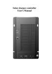
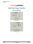
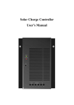
TrakMax 40 User Manual Revision 1.0 windynation TrakMax 40 MPPT Solar Charge Controller CHC-TRMX-40 User’s Manual Page 1 of 20 windynation 03/06/2013 TrakMax 40 User Manual Revision 1.0 Table of Contents 1 2 3 4 5 6 7 Introduction .................................................................................................................................................................. 3 1.1 Limited Warranty ............................................................................................................................................... 3 1.2 Restrictions ........................................................................................................................................................ 3 1.3 Warranty Claims & Return Procedures.............................................................................................................. 3 1.4 Disclaimer.......................................................................................................................................................... 4 1.5 Limitation of Liability .......................................................................................................................................... 4 Product Overview ......................................................................................................................................................... 5 2.1 Features ............................................................................................................................................................ 5 2.2 Specifications .................................................................................................................................................... 5 2.2.1 Electrical Specifications ................................................................................................................................ 5 2.2.2 Physical Specifications .................................................................................................................................. 6 2.2.3 Regulatory Information .................................................................................................................................. 6 Installation .................................................................................................................................................................... 7 3.1 Electrostatic (ESD) Precautions ........................................................................................................................ 7 3.2 Mounting ............................................................................................................................................................ 7 3.3 Grounding .......................................................................................................................................................... 8 3.4 Connections ...................................................................................................................................................... 8 3.5 Overcurrent Protection .....................................................................................................................................10 3.6 Overvoltage – Reverse Polarity Protection .......................................................................................................10 3.7 Parallel Connection ..........................................................................................................................................10 3.8 Communication Port .........................................................................................................................................11 3.8.1 Remote: RJ11 ..............................................................................................................................................11 3.9 Battery Temperature Sensor (BTS) ..................................................................................................................11 3.9.1 Temperature Compensation.........................................................................................................................11 3.9.2 Wiring the Battery Temperature Sensor (BTS).............................................................................................12 Operation ....................................................................................................................................................................12 4.1 Maximum Power Point Tracking (MPPT) ..........................................................................................................12 4.1.1 How MPPT Works ........................................................................................................................................13 4.2 Charge Mode ....................................................................................................................................................13 4.2.1 Factory Default Settings ...............................................................................................................................13 4.2.2 Three Stage Charge.....................................................................................................................................14 4.2.3 Equalization..................................................................................................................................................14 4.3 DC Load Control ...............................................................................................................................................15 4.3.1 Auto Night Disconnect..................................................................................................................................15 4.3.2 Low Voltage Disconnect...............................................................................................................................15 4.3.3 Low Voltage Reconnect ...............................................................................................................................15 4.4 Battery Selection ..............................................................................................................................................15 4.4.1 Battery Type Selector Switch Settings .........................................................................................................15 LED Indicators ............................................................................................................................................................16 5.1 Charge Control .................................................................................................................................................17 5.2 LED Modes .......................................................................................................................................................17 5.2.1 Low Voltage Disconnect (LVD) ....................................................................................................................18 5.2.2 Over Voltage of Load ...................................................................................................................................18 5.2.3 Over Temperature ........................................................................................................................................18 5.2.4 Over Current of Load ...................................................................................................................................18 Troubleshooting And Support .....................................................................................................................................18 6.1 Care..................................................................................................................................................................18 6.2 Troubleshooting ................................................................................................................................................18 6.3 Support .............................................................................................................................................................19 Batteries ......................................................................................................................................................................19 7.1 Battery Types ...................................................................................................................................................19 7.1.1 Automotive Batteries ....................................................................................................................................19 7.1.2 Maintenance-Free Batteries .........................................................................................................................19 7.1.3 Deep-Cycle Batteries ...................................................................................................................................19 7.1.4 Sealed Batteries ...........................................................................................................................................20 7.2 Battery Sizing ...................................................................................................................................................20 7.3 Equalization Charging ......................................................................................................................................20 7.3.1 Equalization Set Points (Non-Sealed Batteries Only)...................................................................................20 Page 2 of 20 windynation 03/06/2013 TrakMax 40 User Manual Revision 1.0 1 INTRODUCTION Windy Nation Inc. (“Windy Nation”) is not assembling the wind unit, installing the solar system, or any other product offered by Windy Nation. Windy Nation, and its directors, officers, and employees disclaim, and by purchasing a Windy Nation wind or solar powered product you accept all liability and responsibility for damage to property, injury, or death arising out of or related to the use or misuse of any product offered by Windy Nation. 1.1 LIMITED WARRANTY Windy Nation warrants that the MPPT Charge Controller (the “Product”), will be free from manufacturing defects in materials and workmanship under normal authorized use consistent with product instructions for a period of one (1) year from the date the original purchaser (“Customer”) receives the Product (the “Warranty Period”). This warranty extends only to the original purchaser. The Customer’s sole and exclusive remedy and the entire liability of Windy Nation, its suppliers and affiliates for breach of the warranty is, at Windy Nation’s option, either (i) to replace the Product (or defective component part(s)) with a new or reconditioned Product (or component part(s)); (ii) to repair the reported problem; or (iii) to refund the purchase price of the Product. Repaired or replaced products are warranted for the remainder of the original warranty period only. No employee, agent, dealer or other person is authorized to give any warranties on behalf of Windy Nation not expressly set forth in this limited warranty. 1.2 RESTRICTIONS No warranty will apply if the Product (i) has been altered or modified except by Windy Nation; (ii) has not been installed, operated, repaired, or maintained in accordance with instructions supplied by Windy Nation; (iii) has been subjected to abnormal physical, thermal or electrical stress, misuse, negligence, or accident. If Windy Nation determines that the problem with the Product is not due to a manufacturing defect in Windy Nation’s workmanship or materials, or otherwise does not qualify for warranty repair, then the Customer will be responsible for the costs of all necessary repairs and expenses incurred by Windy Nation. 1.3 WARRANTY CLAIMS & RETURN PROCEDURES To be eligible for service under this warranty, the Customer must submit a service request within the Warranty Period by contacting Windy Nation in writing or via telephone and obtaining a Returned Materials Authorization (“RMA”) number. This RMA must be obtained before returning any product under this warranty. Notification must include a description of the alleged defect, the manner in which the Product was used, the serial number, and the original purchase date in addition to the name, address, and telephone number of the Customer. Within five (5) business days of the date of notification, Windy Nation will provide the Customer with an RMA number and the location to which the Customer must return the defective Product. Any Product returned for warranty service shall be shipped at the expense and risk of the Customer. The Customer must return the entire Product kit (or, if authorized by Windy Nation, the defective component parts), within fifteen (15) days after issuance of the RMA number. Windy Nation will be under no obligation to accept any returned Product that does not have a valid RMA number. Customer’s failure to return the Product within fifteen (15) days of its receipt of an RMA number may result in cancellation of the RMA. All parts that Windy Nation replaces shall become Windy Nation’s property on the date Windy Nation ships the repaired Product or part back to the Customer. Windy Nation will use all reasonable efforts within thirty (30) days of receipt of the Page 3 of 20 windynation 03/06/2013 TrakMax 40 User Manual Revision 1.0 defective Product to repair or replace such Product. If a warranty claim is invalid for any reason, the Customer will be charged at Windy Nation’s then-current rates for services performed and will be charged for all necessary repairs and expense incurred by Windy Nation. If Windy Nation determines that a warranty claim is valid, it will ship the repaired or replaced Product to Customer at Windy Nation’s cost. 1.4 DISCLAIMER EXCEPT FOR THE EXPRESS LIMITED WARRANTY SET FORTH IN THE PREVIOUS PARAGRAPH, WINDY NATION DISCLAIMS ALL WARRANTIES, EXPRESS, IMPLIED AND STATUTORY INCLUDING, WITHOUT LIMITATION, THE IMPLIED WARRANTIES OF MERCHANTABILITY AND FITNESS FOR A PARTICULAR PURPOSE WITH RESPECT TO ANY PRODUCTS PROVIDED BY WINDY NATION. NO ORAL OR WRITTEN INFORMATION OR ADVICE GIVEN BY WINDY NATION, ITS DEALERS, DISTRIBUTORS, AGENTS OR EMPLOYEES SHALL IN ANY WAY INCREASE THE SCOPE OF THIS WARRANTY. WINDY NATION DOES NOT WARRANT THAT THE QUALITY OR PERFORMANCE OF THE PRODUCTS WILL MEET YOUR REQUIREMENTS OR THAT YOU WILL BE ABLE TO ACHIEVE ANY PARTICULAR RESULTS FROM USE OR MODIFICATION OF THE PRODUCTS. Some jurisdictions do not allow the limitation or exclusion of implied warranties or how long an implied warranty may last, so the above limitations may not apply to you. In any such jurisdiction, the warranty shall be limited to the minimum warranty and period required by law. WINDY NATION EXPRESSLY DISCLAIMS ALL LIABILITY FOR BODILY INJURIES OR DEATH THAT MAY OCCUR, DIRECTLY OR INDIRECTLY, BY USE OF THE PRODUCT BY ANY PERSON. 1.5 LIMITATION OF LIABILITY UNDER NO CIRCUMSTANCES WILL WINDY NATION OR ITS AFFILIATES OR SUPPLIERS BE LIABLE OR RESPONSIBLE FOR ANY LOSS OF USE, INTERRUPTION OF BUSINESS, LOST PROFITS, LOST DATA, OR INDIRECT, SPECIAL, INCIDENTAL, OR CONSEQUENTIAL DAMAGES OF ANY KIND REGARDLESS OF THE FORM OF ACTION, WHETHER IN CONTRACT, TORT (INCLUDING NEGLIGENCE), STRICT LIABILITY OR OTHERWISE, EVEN IF WINDY NATION OR ITS AFFILIATE OR SUPPLIER HAS BEEN ADVISED OF THE POSSIBILITY OF SUCH DAMAGE. Some states do not allow the exclusion or limitation of incidental or consequential damages, so these limitations may not apply to you. Neither Windy Nation nor its affiliates or suppliers will be held liable or responsible for any damage or loss to any items or products connected to, powered by or otherwise attached to the Product. The total cumulative liability to Customer, from all causes of action and all theories of liability, will be limited to and will not exceed the purchase price of the Product paid by Customer. This warranty gives the Customer specific legal rights and the Customer may also have other legal rights that vary from state to state. Page 4 of 20 windynation 03/06/2013 TrakMax 40 User Manual Revision 1.0 2 PRODUCT OVERVIEW The TrakMax solar charge controller is a 40 amp 12/24 Volt Maximum Power Point Tracking (MPPT) photovoltaic (PV) battery charge controller. Through the use of MPPT technology, TrakMax can increase charge current up to 30% or more compared to conventional solar charge controllers. TrakMax’s sophisticated three stage charge control system can be configured to optimize charge parameters to precise battery requirements. The unit is fully protected against voltage transients, over temperature, over current, reverse battery, and reverse PV connections. An automatic current limit feature allows use of the full 40 amp capability without worrying about overload or unnecessary fuse blows from excessive current, voltage, or amp-hour based load control. Series pass Pulse Width Modulation (PWM) charge voltage control combined with a multistage charge control algorithm leads to superior charging and enhanced battery performance. The filtered PWM power control system uses highly efficient and reliable power MOSFET transistors. The MOSFET’s are turned on and off at high frequency to precisely control the charge voltage and the MPPT function. Fully automatic temperature compensation of charge voltage is available to further improve charge control and battery performance. The optional battery temperature sensor (included) is built for long term reliability. The sensor element is environmentally sealed and encapsulated into a lug, which adheres directly to the battery. The TrakMax also includes an isolated RJ11 port for connection to a PC computer for data logging and system monitoring. For large system current applications (greater than 40 amps), multiple TrakMax units can be connected in parallel. 2.1 FEATURES DC Load Output Port Optional battery temperature sensor ensures precise battery charging LED displays to indicate the status of charge Lightning protection Reverse current protection at night Three-stage battery charging (bulk, absorption, and float) with optional temperature compensation Automatic overload protection in both active and passive modes Microprocessor controlled Silent, pulse width modulated (PWM), high efficiency operation Auto detects system voltage (12 or 24 volt) at start up 2.2 SPECIFICATIONS 2.2.1 Electrical Specifications Parameter Battery System Voltage Max Battery Charging Current Load Current Photovoltaic Input Voltage Range Max PV Open Circuit Array Voltage Efficiency Typical Idle Consumption Page 5 of 20 o Value @25 C 12 / 24 VDC (1) 9-18VDC battery voltage = TrakMax auto-detects 12 volt battery system (2) 18-36VDC battery voltage = TrakMax auto-detects 24 volt battery system 40 Amp 15 Amp 12-55VDC 12-30VDC (12 volt battery charging) 30-55VDC (24 volt battery charging) 55VDC 97% min @ full current At idle < 10mA windynation 03/06/2013 TrakMax 40 User Manual Revision 1.0 Overload Protection (DC load) Bulk Charge (adjustable) Floating Charge (adjustable) Equalization Charge Overcharge Disconnection Overcharge Recovery Over-discharge Disconnection Over-discharge Reconnection Temperature Compensation Lead Acid Battery Settings NiCad Battery Settings Load Control Mode 2.0*Inom>5s 1.5*Inom >20s 1.25*Inom temperature controlled 14.6V(default) 29.2V(default) 13.4V(default) 26.8V(default) 14.0V(default) 28.0V(default) 14.8V 29.6V 13.6V 27.2V 10.8 V (default) 21.6V(default) 12.3V 24.6V o o -13.2mV/ C -26.4mV/ C Adjustable Adjustable 1. Low Voltage Reconnect (LVR) 2. Low Voltage Disconnect (LVD): Auto disconnect 12.0-14.0 VDC 24.0-28.0 VDC 10.5-12.5 VDC 21.0-25.0 VDC o o 0 – 40 C (full load) 40 – 60 C (de-rating) Operating 5000 m, Non-Operating 16000 m IP21 Optional remote sensor increases charging precision Low Voltage Reconnect Low Voltage Disconnect Ambient Temperature Altitude Enclosure Protection Class Battery Temperature Sensor (BTS) Terminal Size (fine/single wire) Maximum 6 AWG NOTE: The optional battery temperature sensor automatically adjusts the charging process of the controller according to the type of battery selected by the user. With the battery temperature sensor installed, the controller will increase or decrease the battery charging voltage depending on the temperature of the battery to optimize the charge to the battery and to maintain battery performance. 2.2.2 Physical Specifications Parameter Value Dimension (H x W x D) 7.56” (192mm) x 5.51” (140mm) x 2.6” (66mm) Unit Weight 3.1 lb. (1.4Kg) Mounting Vertical wall mount indoor only Cooling Natural cooling o o o o Operating Temperature 0 C to 40 C (40 C to 60 C derating) o o Storage Temperature -25 C to 70 C Operating Humidity 20 to 80% relative humidity (noncondensing) Non-Operating Humidity Greater than 95% relative humidity o 38.7 C max wet bulb temperature with no damage 2.2.3 Regulatory Information The TrakMax has safety approvals as follows: • UL 1741 • FCC Part 15B • EN6100063:2001 • EN6100061:2001 • EN 603351 FCC Requirements: This device complies with Part 15 of the FCC rules. Operation is subject to the following two conditions: (1) This device may not cause harmful interference, and (2) this device must accept any interference received, including interference that may cause undesired operation. Page 6 of 20 windynation 03/06/2013 TrakMax 40 User Manual Revision 1.0 3 INSTALLATION Insure all terminating connections are clean and tight to prevent arcing and overheating. Do not connect to a PV array capable of producing greater than 40 amps of short circuit current @ 25°C. Do not connect to a PV array with an open circuit voltage (VOC) greater than 55 VDC. For 12 volt battery charging, the open circuit voltage of the PV array must be between 12-30VDC. For 24 volt battery charging, the open circuit voltage of the PV array must be between 30-55VDC. Important: Installations should meet all local codes and standards. Installations of this equipment should only be performed by skilled personnel such as licensed electricians and Certified Renewable Energy (RE) System Installers. 3.1 ELECTROSTATIC (ESD) PRECAUTIONS All electronic circuits may be damaged by static electricity. To minimize the likelihood of electrostatic damage, discharge yourself by touching an electrical ground (e.g.: copper pipe) prior to handling the unit and avoid touching components on the circuit boards. The risk of electrostatic damage is highest when relative humidity is below 40%. 3.2 MOUNTING The mounting location is important to the performance and operating life of the controller. The environment must be dry and protected from water. If required, the controller may be installed in a ventilated enclosure with sufficient airflow. Never install the TrakMax MPPT in a sealed enclosure. The controller may be mounted in an enclosure with sealed batteries, but never with vented/flooded batteries. Battery fumes from vented batteries will corrode and destroy the TrakMax MPPT circuits. 1. Place the TrakMax on a vertical surface protected from direct sun, high temperatures, and water. The TrakMax requires at least 6 in (150 mm) of clearance above and below and at least 1 in (25 mm) on each side for proper air flow as shown in figure 3-1 below. Figure 3-1: Required mounting clearance for airflow. 2. 3. 4. 5. 6. Place a mark on the mounting surface at the top of each keyhole (two per unit). Remove the controller and drill a 3/32 in (2.5 mm) hole at the drill mark. Insert a #10 screw into the pilot holes. Do not tighten the screw completely. Leave a 1/4 in (6 mm) gap between the mounting surface and screw head Carefully align the keyholes on the TrakMax with the screw heads and slide the TrakMax down over the keyhole. 7. Tighten the keyhole screws. 8. Add two additional screws in the lower rectangular mounting cutouts. Warning: Explosion/Corrosion Hazard Do not mount on flammable surface material (e.g.: wooden wall). Page 7 of 20 windynation 03/06/2013 TrakMax 40 User Manual Revision 1.0 3.3 GROUNDING The TrakMax is designed to work with grounded electrical systems. In the controller, ground is not connected to the input terminal and output terminals. Use a copper wire to connect the grounding terminal on the TrakMax enclosure to earth ground. The grounding terminal is located on the lower right corner of the enclosure. Do not connect the system negative conductor to this terminal. NEC requires the use of an external ground fault protection device (GFPD). The system electrical negative should be bonded through a GFPD to earth ground at one (and only one) location. The grounding point may be located in the solar circuit or the battery circuit. 3.4 CONNECTIONS WARNING: Shock Hazard Solar PV array can produce open-circuit voltages in excess of 100 VDC when in sunlight. Verify that the solar input breaker or disconnect has been opened (disconnected) before installing the system wires. Note that the maximum PV open-circuit voltage for the TrakMax is 55 VDC. Do NOT attach the positive and negative PV cables to the TrakMax until the TrakMax has been connected to the positive and negative terminals of the 12 or 24 volt battery bank. It is recommended to use a strain relief (bushings, connectors, clamp connectors, or wire glands) in each of the three ½ in openings. The NEC requires that the wires carrying the system current never exceed 80% of the conductor’s current rating. The table below provides the minimum size of copper wire allowed by NEC. Wire types rated for 75°C and 90°C are included. Wire Type 75°C Wire 90°C Wire 2 2 Copper 6 AWG (16 mm ) 8 AWG (10 mm ) 2 2 Aluminum 4 AWG (25 mm ) 6 AWG (16 mm ) 1) Remove the Wiring Cover from the Top Cover by removing the two securing screws as shown below. 2) Route the relevant cable/wire through the appropriate ½ in opening as noted on the cover. Note: If strain reliefs (i.e.: cable clamps, wire glands) are being used, they must be installed prior to routing the wire, and the wire should route through the clamp. LOAD BATTERY - + Page 8 of 20 - + PV - + windynation 03/06/2013 TrakMax 40 User Manual Revision 1.0 3) Terminal connectors for DC wiring are located on the lower edge of the circuit board. Once the wires have been installed, tighten the terminals with the screw located on the top of the terminals to 1.2Nm (10.6lb-in). Be careful not to over tighten. Tighten Terminals Here Insert Wire/Cable Here a) Load: Maximum 15A DC Load • Connect a cable from the TrakMax terminal marked load negative (–) to the negative terminal of your DC load and tighten the screw. • Connect a cable from the TrakMax terminal marked load positive (+) to the positive terminal of your DC load and tighten the screw. b) Battery: 40A Rated Charge Current • Connect a cable from the TrakMax terminal marked battery negative (–) to the negative (–) battery terminal and tighten the screw. • Connect a cable from the TrakMax terminal marked battery positive (+) on the Solar charge controller to the positive (+) battery terminal and tighten the screw. c) PV: Photovoltaic System • Connect the PV array’s positive (+) output to the terminal marked PV positive (+) on the TrakMax and tighten the screw. • Connect the PV array’s negative (–) output to the terminal marked PV negative (–) on the TrakMax and tighten the screw. 4) Double Check All Connections to ensure they are secure. 5) Replace the Wiring Cover removed in step 1 and secure with the two screws. 6) Tighten the cable clamps (if applicable) CAUTION: Risk of Fire and Shock Connect battery terminals prior to the connection of array terminals. Page 9 of 20 windynation 03/06/2013 TrakMax 40 User Manual Revision 1.0 3.5 OVERCURRENT PROTECTION Circuit breakers or fuses must be installed in both the battery and solar circuits. The protection device ratings and installation methods must conform to NEC requirements. The battery circuit fuses or circuit breaker must be rated to 125% of the maximum current or more. The minimum fuse/breaker rating allowed for use with each TrakMax is 1.25 x 40 Amps = 50 Amps. If the TrakMax controller system detects an overload status, it will automatically reset the over current protection system every 6 minutes. If the fault is still present, the controller will shut off and wait for another 6 minutes. This will occur continuously until the problem is corrected. A disconnect is required for the battery and solar circuits to provide a means for removing power from the TrakMax. Double pole switches or breakers are convenient for disconnecting both solar and battery conductors simultaneously. 3.6 OVERVOLTAGE – REVERSE POLARITY PROTECTION TrakMax is fully protected against reverse polarity and high voltage transients for both the PV and the battery connections. If the battery is connected in the reverse polarity position, the TrakMax inner fuse will open. If the PV array is connected in the reverse polarity position, the TrakMax will not turn on. System Voltage PV Over Voltage Point 12V Battery 30VDC 24V Battery 55VDC 3.7 PARALLEL CONNECTION Multiple TrakMax controllers can be installed in parallel on the same battery bank to achieve higher charging current. For example, connecting two TrakMax units in parallel can allow for 80 amps of charging current, and connecting three TrakMax units in parallel can allow for up to 120 amps of charging current. Additional parallel controllers can also be added in the future. Each TrakMax MPPT Controller must have its own PV array. See figure 3.5 Figure 3.5: Parallel Connection Page 10 of 20 windynation 03/06/2013 TrakMax 40 User Manual Revision 1.0 3.8 COMMUNICATION PORT Network connections allow the TrakMax to communicate with other controllers or computers. 3.8.1 Remote: RJ11 Use standard 4-wire or 6-wire RJ-11 telephone cables (straight-through, not a Null Modem / cross-over). If possible, pull the telephone cable through conduit before crimping on the RJ-11 connectors. If using preassembled cables, take care not to damage the plugs when the cables are pulled through conduit. WARNING: Shock Hazard Never route network cables in the same conduit as the power conductors. 3.9 BATTERY TEMPERATURE SENSOR (BTS) The charge voltage required by batteries changes with battery temperature. Temperature compensation of the charge voltage enhances battery performance and life, and decreases battery maintenance. Automatic temperature compensation can be provided through use of the optional battery temperature sensor (included). Table 3.9 describes approximately how much the voltage may vary depending on the temperature of the batteries. 3.9.1 Temperature Compensation Temperature 12 Volt Units 24 Volt Units Lead Acid NiCad Lead Acid NiCad Celsius Fahrenheit (6 cells) (10 cells) (12 cells) (20 cells) 60 140 1.05 0.7 2.1 1.4 55 131 0.9 0.6 1.8 1.2 50 122 0.75 0.5 1.5 1 45 113 0.6 0.4 1.2 0.8 40 104 0.45 0.3 0.9 0.6 35 95 0.3 0.2 0.6 0.4 30 86 0.15 0.1 0.3 0.2 25 77 0 0 0 0 20 68 0.15 0.1 0.3 0.2 15 59 0.3 0.2 0.6 0.4 10 50 0.45 0.3 0.9 0.6 5 41 0.6 0.4 1.2 0.8 0 32 0.75 0.5 1.5 1 5 23 0.9 0.6 1.8 1.2 10 14 1.05 0.7 2.1 1.4 15 5 1.2 0.8 2.4 1.6 20 4 1.35 0.9 2.7 1.8 25 13 1.5 1 3 2 30 22 1.65 1.1 3.3 2.2 35 31 1.8 1.2 3.6 2.4 40 40 1.95 1.3 3.9 2.6 Table 3.9: Variances in charging voltage based on battery temperature Temperature compensation is based on battery type5mv /cell for lead acid type batteries and 2mv/cell for alkaline type batteries (NiCad or NiFe). The temperature compensation calculations are derived from the following table: Page 11 of 20 windynation 03/06/2013 TrakMax 40 User Manual Revision 1.0 Battery Type 12 Volt Units 24 Volt Units Lead Acid 0.03 volts (30mv) per degree Celsius 0.06 volts (60mv) per degree Celsius NiCad 0.02 volts (20mv) per degree Celsius 0.04 volts (40mv) per degree Celsius 3.9.2 Wiring the Battery Temperature Sensor (BTS) 1) Plug the provided RJ11 cable into the RJ11 socket labeled “BTS” located on the side of the TrakMax as shown below. 2) Secure the BTS on the side of the battery below the electrolyte level as shown below. It is best to place the sensor between batteries and place the batteries in an insulated box to reduce the influence of the ambient temperature outside the battery enclosure. CAUTION: High power electrical systems pose dangers and it is the user's responsibility to be familiar with these dangers and take any necessary action to ensure safe use. Shorting a battery or connecting your controller to a battery can supply huge currents and have serious consequences including explosions, causing fire, damage to equipment, and personal injury. 4 OPERATION 4.1 MAXIMUM POWER POINT TRACKING (MPPT) Maximum Power Point Tracking, frequently referred to as MPPT, is an electronic system that operates the Photovoltaic (PV) modules in a manner that allows the PV modules to produce all the power they are capable of producing. MPPT and associated current boost operation is fully automatic and will function whenever sufficient PV voltage and current are available. The percent increase in output charge current relative to PV current is variable, and will change with operating conditions. When conditions are such that insufficient PV power is available to produce an increase in output current, the unit will stop its internal DC-DC power conversion and operate as a series pass PWM controller with very low forward voltage drop. The principal operating conditions which affect current boost performance are PV array temperature and battery voltage. At constant solar intensity, available PV power changes with PV temperature. A PV array’s power vs. temperature characteristic is such that a cool PV array can produce a higher voltage and more Page 12 of 20 windynation 03/06/2013 TrakMax 40 User Manual Revision 1.0 power, than a hot PV array. When PV voltage is sufficiently high for MPPT to operate, a constant power output is delivered to the battery. Since output power is constant while MPPT is operating, a decrease in battery voltage produces corresponding increase in charge current. This means that the greatest current increase occurs with a combination of cool ambient temperature and low battery voltage. The unit delivers the greatest charge current increase when you need it most, in cold weather with a discharged battery. Additionally, anything that can be done to lower PV array temperature will also lead to increased charge current by increasing PV power production. In cool/comfortable temperatures and typical battery states of charge, most systems see about 10 – 20% increase. Charge current increase can go to zero in hot temperatures, whereas charge current increase can easily exceed 30% with a discharged battery and freezing temperatures. Figure 4.1: Current / Power vs. Voltage Characteristics 4.1.1 How MPPT Works A PV module is a constant current type device. As shown on a typical PV module voltage vs. current curve, current remains relatively constant over a wide range of voltage. A typical 75 watt module is specified to deliver 4.45 amps @ 17 volts @ 25 C cell temperature. Conventional PV controllers essentially connect the PV array directly to the battery when the battery is discharged. When a 75 watt PV module is connected directly to a battery charging at 12 volts, the PV module still provides approximately the same current. But, because output voltage is now at 12 volts rather than 17 volts, the PV module’s power production is artificially limited and the 75W PV module only delivers 53 watts. This wastes 22 watts of available power. TrakMax’s MPPT technology operates in a very different fashion. Under these conditions TrakMax calculates the maximum power voltage (V) at which the PV module delivers maximum power, in this case 17 volts. It then operates the PV module at 17 volts which extracts maximum available power from the PV module. TrakMax continually recalculates the maximum power voltage as operating conditions change. Input power from the maximum power tracking controller, in this case 75 watts, feeds a switching type power converter which reduces the 17 volt input to battery voltage at the output. The full 75 watts which is now being delivered at 12 volts would produce a current of 6.25 amps. A charge current increase of 1.8 amps or 40% is achieved by converting the 22 watts that would have been wasted into useable charge current. Note that this example assumes 100% efficiency to illustrate the principal of operation. In actual operation, the power boost will be somewhat less. 4.2 CHARGE MODE 4.2.1 Page 13 of 20 Factory Default Settings Charge Mode Three (3) Stage Absorption Voltage 14.4V 28.8V Bulk Voltage 14.6V 29.2V Float Voltage 13.4V 26.8V Equalize 14V 28V windynation 03/06/2013 TrakMax 40 User Manual Revision 1.0 4.2.2 Three Stage Charge The TrakMax is configured for a three stage charging process, Bulk, Absorption and Float. The three stage charge process provides a somewhat higher charge voltage to charge the battery quickly and safely. Once the battery is fully charged a somewhat lower voltage is applied to maintain the battery in a fully charged state without excessive water loss. The three stage charge process charges the battery as quickly as possible while minimizing battery water loss and maintenance. 4.2.2.1 Bulk Stage When charge starts the TrakMax attempts to apply the bulk charge voltage to the battery. The system will switch to Bulk charge if the battery is sufficiently discharged and/or insufficient charge current is available to drive the battery up to the bulk voltage set point. During this stage, the batteries are charged at the bulk voltage setting. And the unit delivers as much charge current as possible to rapidly recharge the batteries. When the battery voltage reaches the bulk voltage setting, the charge controller activates the next stage (absorption). TrakMax will again switch to Bulk charge if battery voltage drops below the present charge voltage set point. 4.2.2.2 Absorption Stage During this stage, the unit changes to a constant voltage mode where the absorption voltage is applied to the battery. When charge current decreases to the float transition current setting, the battery is fully charged and the unit switches to the float stage. 4.2.2.3 Float Stage During this stage, the float voltage is applied to the battery to maintain it in a fully charged state. When battery voltage drops below the float setting for a cumulative period, a new bulk cycle will be triggered. 4.2.3 Equalization Equalize charging is a special mode of battery charging. During use, the battery’s cells can become unequal in the voltage and current they can deliver. This is due to a buildup of sulfate on the plates as well as stratified electrolyte. Sulfate prevents the cells from receiving or delivering full power. If the sulfate is left on the plates, it will harden, and permanently reduce the battery’s capacity. Stratification separates the heavier acid from the water, and the concentrated acid remains at the lower portion of the plates, eventually corroding them. Equalizing the batteries every month or two (depending on usage) prolongs the life of the batteries and provides better battery performance. To set the Equalize Charge: 1) Remove all DC loads connected to the batteries. 2) Remove all battery vent caps. 3) Check the battery water level; it should be just over the top of the plates (do not over fill). Use only distilled water for filling batteries. 4) Set the BATTERY TYPE SELECTOR switch to position “0” or “1”. Page 14 of 20 windynation 03/06/2013 TrakMax 40 User Manual Revision 1.0 5) Reset the BATTERY TYPE SELECTOR potentiometer to the appropriate setting for the system batteries when the Equalize charge has completed 4.3 DC LOAD CONTROL The TrakMax can operate as a PV charge controller and can regulate up to 40 Amps of continuous photovoltaic (PV) array current at 12 / 24-volts DC for charging batteries. At the same time the TrakMax can provide a maximum of 15 Amps of current to a DC load, but the 40 Amp current rating is shared between the battery and the DC load. The TrakMax uses voltage set points to determine when to disconnect or reconnect loads depending on battery voltage. TrakMax prevents damage to the battery from over-discharge during periods of poor weather or excessive loads and can charge the batteries in this function. 4.3.1 Auto Night Disconnect When using PV Charge Control mode, the PV array is automatically disconnected from the battery at night to prevent reverse leakage of power and to protect the PV array. 4.3.2 Low Voltage Disconnect When configured as a load controller, the TrakMax will disconnect the load from the batteries when it reaches the low voltage disconnect (LVD) setting. There will be a 1-minute delay after the voltage drops below the LVD setting before the controller actually disconnects the load. 4.3.3 Low Voltage Reconnect The TrakMax will also provide automatic reconnection of the loads at the low voltage reconnect (LVR) setting. Reconnection of the load is allowed once the battery voltage has exceeded the low voltage reconnect (LVR) setting. Loads are automatically reconnected when battery voltage exceeds the low voltage reconnect (LVR) setting for 1 minute. Important: When using the TrakMax in load control do not install the BTS Battery Temperature Sensor 4.4 BATTERY SELECTION It is important to select the battery type that matches the system battery to ensure proper charging and long battery life. The battery type selector (Figure 4.4) is a 10 position rotary switch used to set the TrakMax for the proper float and bulk voltage levels. These levels are selected depending on the type of batteries used. Refer to the table below for the charge voltages in the various switch positions. Refer to the specifications provided by the battery manufacturer and choose a setting that best fits the recommended charging profile. Figure 4.4: Battery Type Selector 4.4.1 Battery Type Selector Switch Settings • Battery Type: The common battery type associated with the specified charging settings. • Float Stage: When the battery is fully charged, the charging voltage will be reduced to the Float voltage setting. Page 15 of 20 windynation 03/06/2013 TrakMax 40 User Manual Revision 1.0 • Equalize: During an equalization cycle, the charging voltage will be held constant at the specified voltage setting. Switch Position Battery Type 12 Volt 24 Volt Charge Function Float Bulk Float Bulk Stage Equalize Stage Equalize (Volts) (Volts) (Volts) (Volts) Equalize charge rate Time Battery Capacity 6 hrs. (Min) / 12 hrs. (Max). Equalize Rate: Battery Capacity (A/hrs) / 40. Battery Charger Rate 6 hrs. (Min) / 12 hrs. (Max). Charger Rate: Set by Battery Rate control. 0 Equalize 1 13.2 *15 26.4 *30 1 Equalize 2 13.2 *15.5 26.4 *31 2 Deep Cell Lead Acid 2 13.3 15 26.6 30 3 Not Specified 13.6 14.3 27.2 28.6 4 Gel Cell 2 13.7 14.4 27.4 28.8 5 Gel Cell 1 13.5 14.1 27 28.2 Typical gel cell battery setting. 6 PcCa Lead Calcium 13.2 14.3 26.4 28.6 Recommended for use with sealed type car batteries. 7 Deep Cycle Lead Acid 1 13.4 14.6 26.8 29.2 Factory Default Setting. Typical deep cycle lead acid batteries. Default Additional Float and Bulk settings for deep cycle, lead acid batteries. Refer to battery manufacturer for settings. Additional setting of Bulk and Float voltages. Refer to battery manufacturer for settings. Recommended for gel cell batteries that specify high float voltages. Refer to battery manufacturer for settings. 8 NiCad 1 14 16 28 32 Use for NiCad battery systems. 9 NiCad 2 14.5 16 29 32 Recommended for use with nickel iron batteries. Important: 1) Switch positions “0” and “1” are for monthly battery maintenance only. Return the switch to the appropriate position for the system’s batteries when Equalize charging has completed. NEVER EQUALIZE GEL BATTERIES! 2) Equalize voltages are displayed in the table with an asterisk (*) – Switch positions “0” and “1” only. 3) Switch position “7” represents the default values as shipped from the factory. 4) Always refer to the battery manufacturer’s specifications for equalization. 5 LED INDICATORS The TrakMax has one multicolor LED and one green LED to indicate the operating status of the controller. Page 16 of 20 windynation 03/06/2013 TrakMax 40 User Manual Revision 1.0 A solid green LED indicates the charging source is functioning properly. A flashing green LED indicates an error condition exists. The multi-color LED indicates the particular operating mode and the battery capacity level. 5.1 CHARGE CONTROL Battery Capacity: <LVD <LVR, >LVD >LVR LED Indication: Red Orange Green Figure 5.1: Battery Capacity LED indicators 5.2 LED MODES If the single color LED or multi-color LED flashes, it indicates an error condition such as over temperature, over current, low voltage disconnect, reverse connection for solar modules, and over voltage of load. The green LED’s flash time depends on the condition or function they are displaying; See table 5.2. Single Color LED Multi-Color LED Operation State On Off State On Off Description Mode ∞ ∞ ∞ ∞ ∞ ∞ ∞ Solid Green ∞ ∞ Charge ON (PV>BV), BAT<LVD ∞ ∞ Charge ON (PV>BV), LVD<BAT<LVR ∞ ∞ Charge ON (PV>BV), BAT>LVR Blink Red 1s 1s Charge ON (PV>BV), BAT<LVD Blink Orange 1s 1s Charge ON (PV>BV), LVD<BAT<LVR Blink Green 1s 1s Charge ON (PV>BV), BAT>LVR Blink Orange 1s 6s BAT under voltage 7 Off ∞ ∞ ∞ ∞ ∞ ∞ ∞ 8 Blink Green 3s 6s Off 9 Blink Green 2s 6s Off 10 Blink Green 1s 6s Off ∞ ∞ Over Current ∞ ∞ Over Temperature ∞ ∞ Over Voltage of Load 11 Blink Green 1s 1s Blink Red 1s 1s PV over voltage 12 Blink Green 1s 1s Blink Orange 1s 1s PV under voltage 13 Blink Green 1s 6s Blink Red ∞ ∞ BAT over voltage 14 Blink Green ∞ ∞ Blink Red ∞ ∞ If >3s, BAT voltage is out of range 1 Solid Green 2 Solid Green 3 Solid Green 4 Solid Green 5 Solid Green 6 Solid Green Solid Red Solid Orange NORMAL DERATED FAULT Upon start-up wait 3s. Table 5.2: Error Mode Indications NOTE: When the controller is charging, the green LED will be solid green. Page 17 of 20 windynation 03/06/2013 TrakMax 40 User Manual Revision 1.0 5.2.1 Low Voltage Disconnect (LVD) When a DC load is connected, if voltage remains below the Low Voltage Disconnect setting, the controller will disconnect after a 6minute delay period. The controller will wait until the voltage rises above the Low Voltage Reconnect setting. 5.2.2 Over Voltage of Load If the controller detects an over voltage of load, it will disconnect the load 5.2.3 Over Temperature The temperature of the controller’s transistors is continuously monitored. This protects the charge controller from damage in high temperature environments. If excessive temperatures are detected while operating in charge mode, the controller will decrease the charge current to reduce the transistor temperature and the green led will be solid green. If the TrakMax is connected with a DC load, the load is disconnected before the transistors reach an excessive temperature and the green LED flashes. Once the temperature has dropped, the loads are reconnected. 5.2.4 Over Current of Load If the controller detects an overload or short circuit on the load, it will automatically reset the over current protection system every 6 minutes. If the default is still present, the controller will shut off and wait another 6 minutes. This will occur continuously until the problem is corrected. 6 TROUBLESHOOTING AND SUPPORT The TrakMax is ruggedly constructed and requires minimal care. It is recommended to inspect all the controller connections two times per year for insulation damage or corrosion and to ensure all connections are tight and secure. CAUTION: Shock Hazard Disconnect all power sources to the controller before removing the wiring box cover. Never remove the cover when voltage exists on the power connections. 6.1 CARE Clean the heat sink and area around the controller of any dirt or debris with a moistened cloth. Inspect the battery bank for cracked or bulging cases and corroded terminals. For wet cell flooded batteries, make sure the water level is maintained according to the manufacturer’s recommendations. 6.2 TROUBLESHOOTING Problem No LED indications, controller does not appear to be powered Charge status LED on, but no output charge current Unit is on, but charge status LED is off Page 18 of 20 Possible Remedies • Check the voltage at the battery terminals on the TrakMax. Battery voltage must be a constant 12 VDC or greater. If no voltage is measured, check wiring connections, fuses, and breakers. • If the voltage on the battery terminals of the controller is between 12 and 36 VDC and no LEDs are lit, contact your dealer for service. • Is the battery voltage greater than the charge voltage set point? This is normal operation. Output is off due to high battery voltage which may be caused by other charging systems. • Battery voltage must be at least 9VDC for the unit to operate. • Check PV connections for reverse polarity. • PV must supply at least 0.25Amp at 3V more than battery voltage to begin charge. • PV- & BAT- must be separate for proper operation. PV- must receive earth ground via shunts inside the TrakMax which internally connect PV- to BAT-. External connection prevents proper operation of internal shunts and current measurement system. Battery voltage is determined windynation 03/06/2013 TrakMax 40 User Manual Revision 1.0 automatically when the unit first receives power. PV open circuit voltage must be 12-30VDC for 12VDC battery charging, and 30-55VDC for 24VDC battery charging. Charge current or PV current is • Check battery voltage, current is reduced if battery voltage is at set points. lower than expected • Check atmospheric haze, dirty PV’s, or sun low on horizon, etc. • Check PV voltage; if system has been changed from 24VDC to 12VDC (or vice versa), battery and PV power must be momentarily disconnected from the TrakMax to reboot the unit and load initial 12 or 24VDC control values. TrakMax considers the PV array to be configured for 24VDC battery charging if PV voltage ever goes above 30VDC. Charge OFF at high temperature The system temporarily shuts down due to high heat sink temperatures. Improve ventilation or reduce PV power to prevent over temp shut down. 6.3 SUPPORT If you are experiencing technical problems, and cannot find a solution in this manual, you can contact Windy Nation Inc. for further assistance. • Call: (805) 323-6445 • Email: [email protected] • Write: 1082 Front Street, Unit B, Ventura, CA 93001 For challenging issues or to just ask a question, consider using our FREE Community Forums! Consult our community of DIY'ers for fast answers to all your questions. Post on our Forums: http://www.windynation.com/community/ 7 BATTERIES Batteries come in different sizes, types, amp-hour capacity, voltages and chemistries. Here are a few guidelines that will help in battery selection, and ensure that the batteries are properly maintained. The best source of the most appropriate settings for the TrakMax will be from the manufacturer or supplier of the batteries. 7.1 BATTERY TYPES 7.1.1 Automotive Batteries Automotive and truck batteries are designed for high cranking power – not deep-cycling. Do not use them unless no other battery type is available. They simply will not last long in a cycling application. 7.1.2 Maintenance-Free Batteries This type of battery is often sold as a RV or marine battery, but is rarely appropriate for use with a PV system. They typically have an additional reserve of electrolyte, but are vented. This is not the same as a sealed battery. 7.1.3 Deep-Cycle Batteries Best suited for use with PV systems, this type of battery is designed to be more deeply discharged before being recharged. Deep-cycle batteries are available in many sizes and types. The most common is the vented liquid electrolyte battery. Vented batteries usually have battery caps. The caps may appear to be sealed, but are not. The caps should be removed periodically to check the level of electrolyte. When a cell is low, distilled water should be added after the battery is fully charged. If the level is extremely low, add only enough distilled water to cover the plates before recharging. The electrolyte volume increases during the charging process and the battery will overflow if it is filled all of the way up before recharging. Use only distilled water because impurities will reduce battery performance. A popular and inexpensive deep-cycle battery is the “golf cart” battery. It is a 6-volt design, typically rated at 220amp-hours. RV and marine deepcycle batteries are also popular for small systems. They are usually referred to as Group 24 or Group 27 Page 19 of 20 windynation 03/06/2013 TrakMax 40 User Manual Revision 1.0 batteries and are rated at 80 to 100 amp-hours at 12volts. Many larger systems use L16 batteries, which are usually rated at 350amp-hours at 6-volts each. They are 17 inches high and weigh about 130pounds. 8D batteries are available with either cranking or deep-cycle construction. Purchase only the deep-cycle version. The 8D is typically rated at 220 amp hours at 12 volts. 7.1.4 Sealed Batteries Another type of battery construction is the sealed gel cell. They do not use battery caps. The electrolyte is in the form of a gel rather than a liquid, which allows the batteries to be mounted in any position. The advantages are no maintenance, long life (800 cycles claimed) and low self-discharge. Absorbed glass mat (AGM) electrolyte batteries are also acceptable. Their electrolyte is contained in mats between the battery plates. Sealed batteries reduce the maintenance requirements for the system and are good for remote applications. They are much more sensitive to the charging process and can be ruined in as little as a day of overcharging. 7.2 BATTERY SIZING Batteries are the fuel tank of the system. The larger the batteries, the longer the system can operate before recharging is necessary. An undersized battery bank results in short battery life and disappointing system performance. To determine the proper battery bank size, compute the number of amp-hours that will be used between charging cycles. Once the required amp-hours are known, size the batteries at approximately twice this amount. Doubling the expected amp-hour usage ensures that the batteries will not be overly discharged and will extend battery life. 7.3 EQUALIZATION CHARGING Approximately every month, some batteries may need to be “equalized.” Since the individual cells of the battery are not identical, some cells may not be fully charged when the charging process is completed. If the batteries have been left in a discharged condition for long periods of time, the plates will have sulfates on them from the electrolyte. If the sulfate remains on the plates for an extended period of time, it will harden and seal off a percentage of the plate area, reducing the capacity of the battery. By equalizing the batteries before the sulfate hardens, the sulfate is removed from the plates. Batteries with liquid electrolyte may become stratified. Stratification concentrates the sulfuric acid into the bottom of the cell while the top becomes diluted. This corrodes the lower portion of the plates, reducing battery life. Mixing of the electrolyte by the formation of gas bubbles during the equalization process reduces stratification. Two methods can be used to determine if a battery needs to be equalized. If possible, measure the voltage of each individual cell while the battery is at rest (not being charged or discharged). A variation of 0.05 volts between cells indicates an imbalance exists. If the battery construction prevents measurement of the individual cell voltages, use a hydrometer. A variation of 0.020 in the specific gravity between cells is considered significant. Both conditions can be corrected by an equalization charge. A proper equalization charge will not damage a vented, liquid electrolyte type battery. It may, however, cause significant electrolyte usage and require that the battery be refilled with distilled water to the correct level. This may be a problem with unattended systems in remote areas which do not receive regular maintenance. Consult the battery manufacturer for their recommendations. 7.3.1 Equalization Set Points (Non-Sealed Batteries Only) Battery Type Bulk Volts Float Volts Equalizing Charge Default Settings 14.0 VDC 13.5 VDC Disabled Sealed Gel Lead Acid 14.1 VDC 13.6 VDC Not recommended; Consult battery manufacturer AGM Lead Acid 14.4 VDC 13.4 VDC Charge to 15.5 VDC or per manufacturer. Maintenance-Free 14.4 VDC 13.4 VDC Limited Only if water level can be checked. RV/Marine Deep-Cycle, Liquid 14.6 VDC 13.4 VDC Charge to 15.5 VDC or per manufacturer. Electrolyte Lead Antimony NiCad or NiFe Alkaline 16.0 VDC 14.5 VDC Not recommended; Consult battery manufacturer Page 20 of 20 windynation 03/06/2013