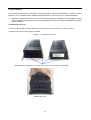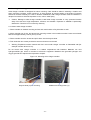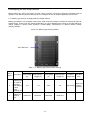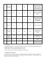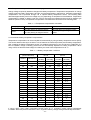
1
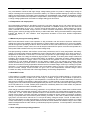
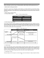
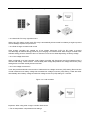
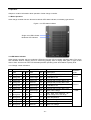
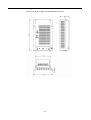
Solarmate charger controller user manual
Contents
Important safety instructions .................................................................................................................... 6
1. Product description ............................................................................................................................... 8
1.1 General description............................................................................................................................. 8
1.2 Features ............................................................................................................................................. 8
1.3 Maximum setting point voltage limit..................................................................................................... 9
1.4 Temperature and output power ........................................................................................................... 9
1.5 Maximum power point tracking (MPPT)............................................................................................... 9
1.6 How MPPT works ............................................................................................................................... 9
1.7 Over voltage / reverse polarity protection ............................................................................................ 9
1.8 Electrostatic handling precautious..................................................................................................... 10
1.9 Solar charger controller setup ........................................................................................................... 10
1.9.1 Factory default settings............................................................................................................... 10
1.10 Three stage charge control ............................................................................................................. 10
1.10.1 Bulk charge .............................................................................................................................. 10
1.10.2 Absorption charge..................................................................................................................... 10
1.10.3 Float charge ..............................................................................................................................11
1.11 Battery temperature sensor (BTS)................................................................................................... 11
1.12 Equalization charge ........................................................................................................................ 11
1.12.1 Photovoltaic charge and load controller......................................................................................11
1.12.2 Automatic PV array night disconnect......................................................................................... 12
1.12.3 Solar charger controller load control.......................................................................................... 12
1.12.4 Low voltage disconnect............................................................................................................. 12
1.12.5 Low voltage reconnect.............................................................................................................. 12
1.13 Optional accessories....................................................................................................................... 13
2. Installation ............................................................................................................................................ 14
2.1 Pre-Installation.................................................................................................................................. 14
2.2 Removing the top cover .................................................................................................................... 14
2.3 Mounting the solar charger controller ................................................................................................ 14
2.3 Mounting the solar charger controller ................................................................................................ 15
2.3.1 Mount the solar charge controller................................................................................................ 15
2.4 Configuring the solar charge controller.............................................................................................. 16
2.4.1 Battery type selector can apply different charger method ............................................................ 16
2.5 Temperature compensation .............................................................................................................. 17
2.5.1 Automatic battery temperature compensation ............................................................................. 18
2.6 Grounding......................................................................................................................................... 19
2.7 DC terminal connector locations........................................................................................................ 19
2.8 Wire Size and over-current protection requirements .......................................................................... 19
2.8.1 Current rating ............................................................................................................................. 19
2.8.2 Surge protection ......................................................................................................................... 20
2.8.3 Over-current protection............................................................................................................... 20
2.9 PV Charge and load control mode wiring........................................................................................... 20
2.10 Easily install in parallel connection .................................................................................................. 21
2.11 Battery type selector ....................................................................................................................... 22
2.12 Installing optional accessories......................................................................................................... 23
2.13 Reinstalling the faceplate ................................................................................................................ 23
3. Operation.............................................................................................................................................. 25
3.1 Basic operation................................................................................................................................. 25
3.2 LED status indicator.......................................................................................................................... 25
3.2.1 Charge control indications .......................................................................................................... 25
4. Troubleshooting................................................................................................................................... 27
5. Specifications....................................................................................................................................... 28
5.1 Specifications ................................................................................................................................... 28
5.2 Environmental................................................................................................................................... 28
5.2.1 Temperature ............................................................................................................................... 28
5.3 Safety and EMC................................................................................................................................ 28
5.3.2 European market: CE ................................................................................................................. 29
5.4 Humidity ........................................................................................................................................... 29
5.4.1 Operating humidity ..................................................................................................................... 29
5.4.2 Non-operating humidity............................................................................................................... 29
5.5 Mechanical features.......................................................................................................................... 29
5.6 Detailed dimension drawing .............................................................................................................. 30
-2-
6. Batteries ............................................................................................................................................... 31
6.1 Battery types..................................................................................................................................... 31
6.2 Automotive batteries ......................................................................................................................... 31
6.3 Maintenance-free batteries................................................................................................................ 31
6.4 Deep-cycle batteries ......................................................................................................................... 31
6.5 Sealed batteries................................................................................................................................ 31
6.6 Battery sizing .................................................................................................................................... 31
6.7 Equalization charging........................................................................................................................ 31
6.8 Equalization setting points (non-sealed batteries only) ...................................................................... 32
-3-
Tables
Table 1 – 1: Factory shipping settings ................................................................................................. 10
Table 1 – 2: Battery type selector switch settings................................................................................. 16
Table 1 – 3: Temperature compensation calculation............................................................................. 18
Table 1 – 4: Battery compensation coefficient...................................................................................... 18
Table 1 – 5: Minimum wire size ........................................................................................................... 20
Table 1 – 6: The LED indicators .......................................................................................................... 26
Table 1 – 7: Troubleshooting list .......................................................................................................... 27
Table 1 – 8: Electrical specification...................................................................................................... 28
Table 1 – 9: Mechanical specification .................................................................................................. 29
Table 1 – 10: Battery equalization ....................................................................................................... 32
Figures
Figure 1 – 1: Bulk charge curve........................................................................................................... 10
Figure 1 – 2: PV charge and load controller......................................................................................... 12
Figure 1 – 3: Load controller ............................................................................................................... 12
Figure 1 – 4: Removing the topcover................................................................................................... 14
Figure 1 – 5: Mounting the solar charge controller............................................................................... 15
Figure 1 – 6: Battery type selector (B.SEL).......................................................................................... 16
Figure 1 – 7: Safety (earth) ground...................................................................................................... 19
Figure 1 – 8: DC terminal connector locations ..................................................................................... 19
Figure 1 – 9: PV charge control mode wiring ....................................................................................... 20
Figure 1 – 10: Parallel connection ....................................................................................................... 21
Figure 1 – 11: battery type selector ..................................................................................................... 22
Figure 1 – 12: Install BTS.................................................................................................................... 23
Figure 1 – 13: Reinstalling the faceplate.............................................................................................. 24
Figure 1 – 14: LED status indicator ..................................................................................................... 25
Figure 1 – 15: Solar charger controller dimension drawing .................................................................. 30
-4-
About manual
Purpose
The purpose of this manual is to provide explanations and procedures for installing, operating, maintaining,
and troubleshooting solar charge controller.
Scope
This manual provides safety guidelines, detailed planning and setup information, procedures for installing
solar charger controller, as well as information about operating and troubleshooting the unit. It does not
provide details about particular brands of batteries. You need to consult individual battery manufacturers for
this information.
Audience
This manual is intended for anyone who needs to install and operate solar charger controller. Installers should
be certified technicians or electricians.
Organization
This manual is organized into six chapters.
Chapter 1 Product description
Chapter 2 Installation
Chapter 3 Operation
Chapter 4 Troubleshooting
Chapter 5 Specification
Chapter 6 Battery
-5-
Important safety instructions
Save these instructions
This manual contains important instructions for solar charger controller that shall be followed during
installation and maintenance.
General
1. Refer installation and servicing to qualified service personnel. Incorrect installation or use may result in risk
of fire. No user serviceable parts in this unit.
2. Remove all sources of power, photovoltaic and battery before servicing or installing.
3. Warning – risk of explosive gases
(1) When solar charger controller is working, please DO NOT touch it because temperature is too high.
(2) Working in vicinity of lead-acid batteries is dangerous. Batteries produce explosive gasses during normal
battery operation.
(3) To reduce risk of battery explosion, follow these instructions and those published by battery manufacturer
and manufacturer of any equipment you intend to use in vicinity of battery.
4. Personal precautions
(1) Someone should be within range of your voice or close enough to come to your aid when you work near a
lead-acid battery.
(2) Have plenty of fresh water and soap nearby in case battery acid contacts skin, clothing or eyes.
(3) Wear complete eye protection and clothing protection. Avoid touching eyes while working near battery.
(4) If battery acid contacts skin or clothing, wash immediately with soap and water. If acid enters eye,
immediately flood eye with running cold water for at least 10 minutes and get medical attention immediately.
(5) NEVER smoke or allow a spark or flame in vicinity of battery.
(6) Be extra cautious to reduce risk of dropping metal tool onto battery. It might spark or short circuit battery or
other electrical part that may cause explosion.
(7) Remove personal metal items such as rings, bracelets, necklaces, and watches when working with a
lead-acid battery. A lead-acid battery can produce a short circuit current high enough to weld a ring or the like
to metal, causing a severe burn.
5. Preparing to charge
(1) Never charge a frozen battery.
(2) Be sure battery is mounted in a well-ventilated compartment.
(3) Add distilled water in each cell until battery acid reaches level specified by battery manufacturer. This
helps purge excessive gas from cells. Do not overfill. For a battery without cell caps, carefully follow
manufacturers charging instructions.
6. Charger location & installation
(1) Controller employs components that tend to produce arcs or sparks. NEVER install in battery compartment
or in presence of explosive gases.
(2) Protect all wiring from physical damage, vibration and excessive heat.
(3) Insure that controller is properly setup for battery being charged.
(4) Do not expose controller to rain or snow.
(5) Insure all terminating connections are clean and tight to prevent arcing and overheating.
(6) Charging system must be properly installed as described in these instructions prior to operation.
(7) Do not connect to a PV array capable of producing greater than 40 amps of short circuit current @ 25°C.
(8) Do not connect input to DC source directly with load, solar charger controller need to be powered by solar
panel.
(9) Do not short-circuit DC output port, it will damage solar charger controller.
-6-
Symbol
--Warning
--Dangerous Voltage
--Alternative Current
--Direct Current
--Protective Earth
--ESD
Abbreviations and Acronyms
BTS
DC
LED
LVD
LVR
B.SELECT
CHG.MODE
PV
MPPT
PWM
RE
Battery temperature sensor
Direct current
Light emitting diode
Low voltage disconnect
Low voltage reconnect
Battery type selector
Charge mode
Photovoltaic
Maximum power point tracking
Pulse width modulation
Renewable energy
-7-
1. Product description
1.1 General description
Solar charger controller is a 40 amp 12/24 voltage maximum power point tracking (MPPT) photovoltaic (PV)
battery charge controller. Through use of MPPT technology, solar charger controller can increase charge
current up to 30% or more compared to conventional controllers. Solar charger controller’s sophisticated three
stage charge control system can be configured to optimize charge parameters to precise battery requirements.
The unit is fully protected against voltage transients, over temperature, over current, reverse battery and
reverse PV connections. An automatic current limit feature allows use of full 40 amp capability without
worrying about overload from excessive current, voltage or amp-hour based load control.
Solarmate passes pulse width modulation (PWM) charge voltage control combined with a multistage charge
control algorithm leads to superior charging and enhanced battery performance. Filtered PWM power control
system uses highly efficient and reliable power MOSFET transistors. MOSFET’s are turned on and off at high
frequency to precisely control charge voltage and MPPT.
Fully automatic temperature compensation of charge voltage is available to further improve charge control
and battery performance. Optional battery temperature sensor is built for long term reliability. The sensor
element is environmentally sealed and encapsulated into a plastic lug which adheres to directly to battery
terminal and by RJ11 port connect with the unit, and solar charger controller also includes an isolated RS232
port for connection to a PC computer for data logging and system monitoring.
Solar charger controller can easily install in parallel connection of output, so it also suitable for large system
current application condition.
1.2 Features
1. A DC Load output port
2. An optional battery temperature sensor ensures precise battery charging
3. LED displays to indicate the status of charge
4. Lightning protection
5. Reverse current at night
6. Three-stage battery charging (bulk, absorption, and float) with optional temperature compensation
7. Automatic overload protection
8. Microprocessor controlled
9. Silent, pulse width modulated (PWM), high efficiency operation
-8-
1.3 Maximum setting point voltage limit
Very cold batteries combined with high charge voltage setting points can produce voltages high enough to
disrupt or damage other equipment connected to battery. To minimize possible damage a maximum voltage
setting point limit feature is provided. Factory defaults can be adjustable using software. Regardless of what
setting point values result from temperature compensation, solar charger controller will never attempt to apply
a charge voltage greater than the maximum voltage setting point limit value.
1.4 Temperature and output power
Over temperature protection is provided to protect the unit from damage due to high output power at high
ambient temperatures. When mounted vertically as described in installation section, the unit can deliver full
output in a temperature of up to 40℃, and the unit will de-rate output in 40-60℃. While operating in charge
mode, controller will decrease charge current to reduce transistor temperature and the green led will be
blinking green, reducing average power delivery to within safe limits. During thermal shutdown charge status
indicator will display an “Off” condition. Over temperature shutdown occurs when ambient temperature
reaches 60℃.
1.5 Maximum power point tracking (MPPT)
MPPT and associated current boost operation is fully automatic and will function whenever sufficient PV
voltage and current are available. Percent increase in output charge current relative to PV current is variable,
and will change with operating conditions. When conditions are such that insufficient PV power is available to
produce an increase in output current, the unit will stop it’s internal DC-DC power conversion and operate as a
series pass PWM controller with very low forward voltage drop.
Principal operating conditions which affect current boost performance are PV array temperature and battery
voltage. At constant solar intensity available PV power changes with PV temperature. A PV array’s power vs.
temperature characteristic is such that a cool PV array can produce a higher voltage and more power, than a
hot PV array. When PV voltage is sufficiently high for MPPT to operate, a constant power output is delivered
to battery. Since output power is constant while MPPT is operating, a decrease in battery voltage produces
corresponding increase in charge current. This means that the greatest current increase occurs with a
combination of cool ambient temperature and low battery voltage. The unit delivers the greatest charge
current increase when you need it most, in cold weather with a discharged battery. Additionally, anything that
can be done to lower PV array temperature will also lead to increased charge current by increasing PV power
production. In cool/comfortable temperatures and typical battery states of charge, most systems see about
10-20% increase. Charge current increase can go to zero in hot temperatures, whereas charge current
increase can easily exceed 30% with a discharged battery and freezing temperatures.
1.6 How MPPT works
A PV module is a constant current type device. As shown on a typical PV module voltage vs. current curve,
current remains relatively constant over a wide range of voltage. A typical 75 watt module is specified to
deliver 4.45 amps @ 17 volts @ 25 C cell temperature. Conventional PV controllers essentially connect PV
array directly to battery when battery is discharged. When a 75 watt module is connected directly to a battery
charging at 12 volts, module still provides approximately the same current. But, because output voltage is now
at 12 volts rather than 17 volts, module power production is artificially limited and 75W module only delivers
53 watts. This wastes 22 watts of available power.
Solar charger controller’s MPPT technology operates in a very different fashion. Under these conditions solar
charger controller calculates the maximum power voltage (V) at which PV module delivers maximum power,
in this case 17 volts. It then MPPT operates module 17 volts which extracts maximum available power from
module. Solar charger controller continually recalculates the maximum power voltage as operating conditions
change. Input power from the maximum power tracking controller, in this case 75 watts, feeds a switching
type power converter which reduces the 17 volt input to battery voltage at output. The full 75 watts which is
now being delivered at 12 volts would produce a current of 6.25 amps. A charge current increase of 1.8 amps
or 40% is achieved by converting the 22 watts that would have been wasted into useable charge current. Note
that this example assumes 100% efficiency to illustrate principal of operation. In actual operation, boost will be
somewhat less.
1.7 Over voltage/reverse polarity protection
-9-
Solar charger controller is fully protected against reverse polarity and high voltage transients for both PV and
battery connections. If battery is connected reverse polarity, solar charger controller will be protected by inner
fuse and fuse will be open. If PV array is connected reverse polarity charge control system will not turn on.
1.8 Electrostatic handling precautious
All electronic circuits may be damaged by static electricity. To minimize likelihood of electrostatic damage,
discharge yourself by touching a water faucet or other electrical ground prior to handling the unit and avoid
touching components on circuit boards. Risk of electrostatic damage is the highest when relative humidity is
below 40%.
1.9 Solar charger controller setup
1.9.1 Factory default settings
Table 1-1: Factory shipping settings
Charge mode
Absorption voltage
Bulk voltage
Float voltage
Equalize
Basic settings
3 stage
14.4/28.8V
14.6/29.2V
13.4/26.8V
14/28V
1.10 Three stage charge control
Solar charger controller is typically configured for a three stage charging process, bulk, absorption and float.
The three stage charge process provides a somewhat higher charge voltage to charge the battery quickly and
safely. Once battery is fully charged a somewhat lower voltage is applied maintain battery in a fully charged
state without excessive water loss. The three stage charge process charges battery as quickly as possible
while minimizing battery water loss and maintenance.
Figure 1 – 1: Bulk charge curve
1.10.1 Bulk charge
When charge starts solar charger controller attempts to apply bulk charge voltage to battery. The system will
switch to bulk charge if battery is sufficiently discharged and/or insufficient charge current is available to drive
battery up to bulk voltage setting point. During bulk charge stage the unit delivers as much charge current as
possible to rapidly recharge battery. Once charge control system enters absorption or float, the unit will again
switch to bulk charge if battery voltage drops below the present charge voltage setting point.
1.10.2 Absorption charge
During this stage, the unit changes to a constant voltage mode where absorption voltage is applied to battery.
- 10 -
When charge current decreases to float transition current setting, battery is fully charged and the unit switches
to the float stage.
1.10.3 Float charge
During this stage, float voltage is applied to battery to maintain it in a fully charged state.
When battery voltage drops below float setting for a cumulative period, a new bulk cycle will be triggered.
1.11 Battery temperature sensor (BTS)
Charge voltage required by batteries changes with battery temperature. Temperature compensation of charge
voltage enhances battery performance and life, and decreases battery maintenance. Automatic temperature
compensation can be provided through use of optional battery temperature sensor. The following table
describes approximately how much voltage may vary depending on temperature of batteries.
1.12 Equalization charge
Equalize charging is a special mode of battery charging. During use, battery’s cells can become unequal in
voltage and current they can deliver. This is due to a buildup of sulfate on plates as well as stratified
electrolyte. Sulfate prevents cells from receiving or delivering full power. If sulfate is left on plates, it will
harden, and permanently reduce battery’s capacity. Stratification separates heaver acid from water, and
concentrated acid remains at lower portion of plates, eventually corroding them. Equalizing batteries every
month or two (depending on usage) prolongs life of batteries and provides better battery performance.
To set the equalize charge:
1. Remove all DC loads connected to batteries.
2. Remove all battery vent caps.
3. Check battery water level, it should be just over the top of plates (do not over fill). Use only distilled water
for filling batteries.
4. Set BATTERY TYPE SELECTOR switch to position “0” or “1”(position “1” is reserved).
5. Reset BATTERY TYPE SELECTOR potentiometer to an appropriate setting for system batteries when
equalize charge has completed.
1.12.1 Photovoltaic charge and load controller
Solar charger controller can operate as a PV charge controller. It can regulate up to 40amps of continuous
photovoltaic (PV) array current at 12 / 24-volts DC for charging batteries, at the same time solar charger
controller can provide the maximum 15Amp current to DC load ,but the rating 40Amp current is shared battery
with DC load.
When PV voltage is lower, battery will provide power to DC load, In load control condition, solar charger
controller controls when to remove load from system when an over-discharge or over-load situation occurs.
Solar charger controller uses software setting points to determine when to disconnect or reconnect loads
depending on battery voltage. Solar charger controller prevents damage to battery from over-discharge during
periods of poor weather or excessive loads. Solar charger controller can charge batteries when in this
function.
- 11 -
Figure 1-2: PV charge and load controller
1.12.2 Automatic PV array night disconnect
When using PV charge control mode, PV array is automatically disconnected from battery at night to prevent
reverse leakage of power and protect PV.
1.12.3 Solar charger controller load control
Solar charger controller can operate as a low voltage disconnect (LVD) for DC loads to prevent
over-discharge to batteries during periods of poor charging or excessive loads. Solar charger controller uses
software setting points to determine when to disconnect or reconnect loads depending on battery voltage.
1.12.4 Low voltage disconnect
When configured as a load controller, solar charger controller will disconnect load from batteries when it
reaches LVD setting. There will be a 1-minute delay after voltage drops below low voltage disconnect (LVD)
setting before controller actually disconnects load.
1.12.5 Low voltage reconnection
It can also provide automatic reconnection of loads at the low voltage reconnect (LVR) setting. Reconnection
of load is allowed once battery voltage has exceeded low voltage reconnect (LVR) setting. Loads are either
automatically when battery voltage exceeds low voltage reconnect (LVR) setting for 1 minutes.
Figure 1-3: Load controller
Important: When using solar charger controller load control:
1. Do not temperature-compensate these settings.
- 12 -
2. Do not install optional battery temperature compensation sensor.
1.13 Optional accessories
The follow accessories can be purchased for use with solar charger controller:
Battery temperature sensor (BTS): BTS is installed on the side of battery and attaches to RS232 port inside
solar charger controller. It provides accurate sensing of battery temperature and uses this reading to control
charging. Using this accessory can extend battery life and improve overall charging.
- 13 -
2. Installation
2.1 Pre-installation
The instructions that follow are applicable to typical installation. For special applications, consult a qualified
electrician or your certified dealer. Installation procedures will vary according to your specific application.
²
Important: Installations should meet all local codes and standards. Installations of this equipment should
only be performed by skilled personnel such as qualified electricians and certified renewable energy (RE)
system installers.
2.2 Removing top cover
1. Access inside of solar charger controller by removing the four screws M3*6 on cover of the unit.
2. Remove top cover of solar charger controller.
Figure 1 – 4: Removing top cover
Remove these screws M3*6 (*4) from top cover to access heat sink of controller
Remove top cover
- 14 -
2.3 Mounting solar charger controller
Solar charger controller is designed for indoor mounting. Care should be taken in selecting a location and
when mounting enclosure. Avoid mounting it in direct sunlight to prevent heating of enclosure. Enclosure
should be mounted vertically on a wall. In outdoor installations, solar charge controller must be installed in a
rainproof enclosure to eliminate exposure to rain, mist or water-spray.
²
Caution: Damage to solar charge controller, install solar charge controller in a dry, protected location
away from sources of high temperature, moisture, and vibration. Exposure to saltwater is particularly
destructive. Corrosion is not covered by warranty.
2.3.1 Mount solar charge controller
1. Place controller on desired mounting surface and mark location of keyhole slots on wall.
2. Move controller out of way, and secure two mounting screws in the locations marked. Leave screw heads
backed out approximately 1/4inch (6 mm) or less.
3. Place controller onto the screws and pull it down into the keyhole slots.
4. Then insert the two screws provided to secure enclosure onto the wall.
²
Warning: Explosion/corrosion hazard and don’t mount solar charger controller on flammable wall (for
example: wooden all and so on).
Do not locate solar charge controller in a sealed compartment with batteries. Batteries can vent
hydrogen-sulfide gas, which is corrosive to electronic equipment. Batteries also generate hydrogen and
oxygen gas that can explode when exposed to a spark.
Figure 1-5: Mounting solar charge controller
Keyhole slots (*2) for mounting
Additional mounting holes (*2)
- 15 -
2.4 Configuring the solar charge controller
Before making any wiring connections to solar charge controller, it must be configured for desired mode of
operation. The following sections describe how to configure the unit for desired application and function.
2.4.1 Battery type selector can apply different charger method
Battery type selector is a 10 position rotary switch used to set solar charger controller for proper float and bulk
voltage levels. These levels are selected depending on type of batteries used. Refer to the table below for
charge voltages in various switch positions. Consult battery manufacturer for optimum battery voltage
charging settings.
Figure 1-6: Battery type selector (B.SEL)
BAT.SELLECT
Table 1 – 2: Battery type selector switch settings
12-volt
Switch
Description Float voltage Bulk/equalize
position
(V)
voltage (V)
0
1
Equalize 1 equalizes at a
rate equal to
the battery
bank capacity
(in amp
hours)
divided by 40.
Equalize 2
–depend on
customer
reset
13.2
Reserved
24-volt
Float voltage
(V)
Bulk/equalize
voltage (V)
Equalize
charge rate
Equalize
time
26.4
*30
Max 40Amp
Depend on
battery
capacity
Reserved
Reserved
*15
Reserved
Charge function
- 16 -
2
Deep cell
lead acid 2
13.3
15
26.6
30
Provides an additional
float and bulk settings
for deep cycle, lead acid
batteries. Refer to
battery manufacturer
recommendation for
float and bulk settings.
3
Not specified
13.6
14.3
27.2
28.6
Provides an additional
setting of bulk and float
voltages.
4
GEL cell 2
13.7
14.4
27.4
28.8
Recommended for GEL
cell batteries that specify
high float voltages.
Check with battery
manufacturer.
5
GEL cell 1
13.5
14.1
27
28.2
Typical gel cell setting.
6
PcCa-lead
calcium
13.2
14.3
26.4
28.6
Use this setting for
sealed type car
batteries.
7
Deep cycle
lead acid 1
(default
setting)
13.4
14.6
26.8
29.2
Factory setting for
typical deep cycle lead
acid batteries.
8
NiCad 1
14
16
28
32
Use for NiCad battery
systems.
9
NiCad 2
14.5
16
29
32
Recommended for use
with nickel iron batteries.
²
Important:
1. Switch positions “0” and “1” are for monthly battery maintenance only. Equalize voltages are displayed in
the table with an asterisk (*) – Switch positions “0” and “1” only.
2. Switch position “7” is default values as shipped from factory.
3. Always refer to battery manufacturer’s specifications for equalization.
2.5 Temperature compensation
For optimal battery charging, bulk and float charge rates should be adjusted according to temperature of
battery. When battery charging voltages are compensated based on temperature, charge voltage will vary
depending on temperature around batteries.
- 17 -
2.5.1 Temperature compensation based on battery type
Charge voltage required by batteries changes with battery temperature. Temperature compensation of charge
voltage enhances battery performance and life, and decreases battery maintenance. Automatic temperature
compensation can be provided through use of optional battery temperature sensor. The following table
describes approximately how much voltage may vary depending on temperature of the batteries. Temperature
compensation is based on battery type-5mv /cell for lead acid type batteries and 2mv/cell for alkaline type
batteries (NiCad or NiFe). Temperature compensation calculations are derived from the following table.
Table 1 – 3: Temperature compensation calculation
Battery type
Lead acid
NiCad
12 -volt
0.03 volts (30mv) per degree Celsius
0.02 volts (20mv) per degree Celsius
24-volt
0.06 volts (60mv) per degree Celsius
0.04 volts (40mv) per degree
Celsius
2.5.2 Automatic battery temperature compensation
Temperature compensation can be accomplished automatically by using a battery temperature sensor (BTS).
The sensor attaches directly to the side of one of batteries in bank and provides precise battery temperature.
See “Installing the battery temperature sensor” for detailed instructions on how and where to install BTS. If a
BTS is installed, charge controlling process will be automatically adjusted for battery temperature. When
using a BTS, set bulk and float voltage for a battery at normal room temperature for 25 °C.
Table 1 – 4: Battery compensation coefficient
Temperature
(around the BTS)
Celsius
Fahrenheit
60
55
50
45
40
35
30
25
20
15
10
5
0
-5
-10
-15
-20
-25
-30
-35
-40
140
131
122
113
104
95
86
77
68
59
50
41
32
23
14
5
-4
-13
-22
-31
-40
12-volt
Lead acid
(6 cells)
-1.05
-0.9
-0.75
-0.6
-0.45
-0.3
-0.15
0
0.15
0.3
0.45
0.6
0.75
0.9
1.05
1.2
1.35
1.5
1.65
1.8
1.95
NiCad
(10 cells)
-0.7
-0.6
-0.5
-0.4
-0.3
-0.2
-0.1
0
0.1
0.2
0.3
0.4
0.5
0.6
0.7
0.8
0.9
1
1.1
1.2
1.3
24-volt
Lead acid
(12 cells)
NiCad
(20 cells)
-2.1
-1.8
-1.5
-1.2
-0.9
-0.6
-0.3
0
0.3
0.6
0.9
1.2
1.5
1.8
2.1
2.4
2.7
3
3.3
3.6
3.9
-1.4
-1.2
-1
-0.8
-0.6
-0.4
-0.2
0
0.2
0.4
0.6
0.8
1
1.2
1.4
1.6
1.8
2
2.2
2.4
2.6
If using a BTS, when battery temperature drops below 25 °C, regulation voltage setting automatically
increases. When temperature rises above 25°C, regulation battery voltage setting automatically decreases.
- 18 -
2.6 Grounding
Solar charge controller is designed to work with grounded electrical systems. In solar charger controller
ground is not connected to input terminal and output terminal so customer can connect ground to battery + or
batter -. But don’t connect battery terminal and PV output terminal with ground at same time.
Figure 1-7: Safety (earth) ground
Safety (earth) ground
2.7 DC terminal connector locations
Terminal connectors for DC wiring are located on the lower edge of circuit board.
Terminal torque requirements:
Once wires have been installed, torque terminals as follows. Be careful not to over tighten.
Figure 1-8: DC terminal connector locations
Load negative (-)
PV negative (-)
Load positive (+)
PV positive (+)
Battery negative (-)
Battery positive (+)
2.8 Wire size and over-current protection requirements
The wiring, over-current protection devices (fuses), and installation methods used must conform to all national
and local electrical code requirements. Wiring should be protected from physical damage with conduit or a
strain relief clamp.
2.8.1 Current rating
Solar charge controller is rated for a rating continuous current of 40 amps. Since PV outputs can vary due to
array size or sunlight striking it, the safe minimum wire size should be based on the maximum current ratings.
- 19 -
2.8.2 Surge protection
Since PV arrays are often mounted on an elevated structure and thus are more susceptible to lightning strikes,
protection from lightning-induced power surges and other transient power disturbances between PV array and
solar charge controller are strongly recommended. Because solar charger controller has wider input voltage
range 15-55VDC.
2.8.3 Over-current protection
If controller detects an overload, it will automatically resets over current protection system every 6 minutes. If
the default is still present, controller will shut off and wait another 6 minutes. This will occur continuously until
the problem is corrected.
Table 1-5: Minimum wire size
Controller
12/24VDC
Minimum wire size
#8AWG
2.9 PV charge and load control mode wiring
The procedure below is illustrated in Figure 1-9
²
WARNING: Shock hazard
PV arrays generate voltage whenever light strikes surface of array. Before connecting solar charge controller,
cover or disconnect array to prevent any current from being generated.
1. Connect the PV array’s positive (+) output to the terminal marked PV positive (+) on solar charge controller
and tighten the screws.
2. Connect the PV array’s negative (–) output to the terminal marked PV negative (–) on solar charge
controller and tighten the screws.
3. Connect the terminal marked battery negative (–) on solar charge controller to the negative (–) battery
terminal and tighten the screws.
4. Connect the terminal marked battery positive (+) on solar charge controller to the positive (+) battery
terminal and tighten the screws.
5. Connect the terminal marked load negative (–) on solar charge controller to the negative (–) load terminal
and tighten the screws.
6. Connect the terminal marked load positive (+) on solar charger controller to the positive (+) battery terminal
and tighten the screws.
7. Connect a cable from controller’s other terminal marked load negative (–) to the negative terminal of your
DC load and tighten the screws.
8. Connect a cable from controller’s other terminal marked load positive (+) to the positive terminal of your DC
load and tighten the screws.
Figure 1 – 9: PV charge control mode wiring
Load negative (-)
PV negative (-)
- 20 -
Load positive (+)
PV positive (+)
2.10 Easily install in parallel connection
In order to get more than 40A charge current, Output of solar charger controller can be connected in parallel.
For example, connecting 2 solar charger controller in parallel can get 80A charger current, and connecting 3
solar charger controller in parallel can get 120A charger current.
Figure 1-10: Parallel connection
- 21 -
2.11 Battery type selector
Please see 2.5.1 section, which you find the different one of 10 positions stand for different battery types
specified. You can select solar charger controller for proper float and bulk voltage levels. These levels are
selected depending on type of batteries used. Refer to the table below for charge voltages in various switch
positions. Consult battery manufacturer for optimum battery voltage charging settings.
Figure 1-11: Battery type selector
Please use truss screwdriver to
select proper position
- 22 -
2.12 Installing optional accessories
The following sections describe how to install optional accessories available for solar charge controller.
To install battery temperature sensor (BTS)
1. Install BTS on the side of battery below electrolyte level. It is best to place the sensor between batteries and
place batteries in an insulated box to reduce influence of ambient temperature outside battery enclosure.
2. Insert RJ-11 plug on the other end of the BTS into BTS port on solar charge controller.
Figure 1-12: Install BTS
RJ-11 Port
2.13 Reinstalling the faceplate
To reinstall the faceplate on solar charge controller:
1. Align top cover so that two screw holes in corners line up.
2. Insert screws into screw holes and tighten.
- 23 -
Figure 1-13: Reinstalling the faceplate
Align these screw holes, replace the screw to secure the top cover
- 24 -
3. Operation
Chapter 3 contains information about operation of solar charge controller.
3.1 Basic Operation
Solar charge controller has one blue and multicolor LED status indicator, one battery type selector.
Figure 1-14: LED status indicator
Single color LED indicator
Multicolor LED indicator
3.2 LED Status Indicator
Solar charger controller has one multicolor LED and one green LED to indicate operating status. The green
LED indicates whether charging source is functioning properly when it display solid green or type of fault
when it flash. And the multi color LED indicates particular operating mode and batteries capacity level.
3.2.1 Charge control indications
LED1
LED2
State
On
Off
State
On
Off
1
Solid green
All
2
Solid green
3
0
Solid red
All
0
All
0
Solid orange
All
0
Charge ON( PV>BV), BAT<LVD
Charge ON( PV>BV),
LVD<BAT<LVR
Solid green
All
0
Solid green
All
0
Charge ON( PV>BV), BAT>LVR
4
Solid green
All
0
Blink red
1s
1s
5
Solid green
All
0
Blink orange
1s
1s
Charge ON( PV>BV), BAT<LVD
Charge ON( PV>BV),
LVD<BAT<LVR
6
Solid green
All
0
Blink green
1s
1s
Charge ON( PV>BV), BAT>LVR
7
Off
0
all
Blink orange
1s
6s
BAT under voltage
8
Blink green
3s
6s
Off
0
all
DC load over current or dc
load voltage out of the range
9
Blink green
2s
6s
Off
0
all
Over temperature
10
Blink green
1s
1s
Blink red
1s
1s
PV over voltage
11
Blink green
1s
1s
Blink orange
1s
1s
PV under voltage
12
Blink green
1s
6s
Blink red
0
all
BAT over voltage
- 25 -
Description
Operation
mode
Normal
Derated
Fault
13
Blink green
All
0
Blink red
0
all
when solar charger controller starts,
wait for 3s; if the start time is over
3s, then mean that the BAT voltage
is out of the range
Table 1-6: The LED indicators
NOTE:
When solar charger controller is charging, the green LED will be solid green.
1. Low voltage disconnect
When connected with DC load, if voltage remains below low voltage disconnect setting, controller will
disconnect after a 1-minute delay period. And controller waits until voltage rises above low voltage recovery
setting.
2. Over voltage of load
If controller detects an over voltage of load, it will disconnect load.
3. Over temperature
Temperature of the controller’s transistors is continuously monitored. This protects charge controller from
damage in high temperature environments if excessive temperatures are detected. While operating in charge
mode, controller will decrease charge current to reduce transistor temperature and the green led will be solid
green. If solar charger controller connected with DC load, load is disconnected before transistors reach an
excessive temperature and the green LED flashes. Once temperature has dropped, loads are reconnected.
4. Over current of load
If controller detects an overload or short circuit of load, it will automatically resets over current protection
system every 6 minutes. If the default is still present, controller will shut off and wait another 6 minutes. This
will occur continuously until the problem is corrected.
- 26 -
4. Troubleshooting
Table 1-7: Troubleshooting list
Symptom
Completely dead, no display
Probable cause
No battery power
Unit will not turn on(charge status
LED off), display if attached is OK
PV disconnected
PV reverse polarity
PV- connected to BAT- external to
controller
Charge status LED on, but no
output charge current
Battery voltage greater than
charge voltage setting point.
Battery voltage too low
Charge current is lower than
expected, PV current may be low
as well
Battery is highly charged
Worn out PV modules
Low isolation
PV- connected to BATNominal PV voltage has changed
from 24VDC to 12VDC
Charge OFF at high temperature
System temporarily shuts down
due to high heat sink temperature
- 27 -
Items to examine or correct
Battery disconnected, overly
discharged, or connected
reversely, no display polarity.
Battery powers system, not PV.
PV disconnected
PV must supply at least 0.25Amp
at 3V more than battery voltage to
begin charge.
PV reverse polarity, reverse
polarity PV will cause heat sink to
heat.
PV- & BAT- must be separate for
proper operation. PV- must receive
earth ground via shunts inside the
solar charger controller which
internally connect PV- to BAT-.
External connection prevents
proper operation of internal shunts
and current measurement system.
Battery voltage is determined
automatically when the unit first
receives power. Voltage must be
less than 30VDC for 12VDC
battery, or greater than 30VDC for
24VDC battery. Apply battery
quickly and crisply.
This is normal operation. Output is
off due to high battery voltage
which may be caused by other
charging systems.
Battery voltage must be at least
9VDC for the unit to operate.
Normal operation, current is
reduced if battery voltage is at
setting point
Replace, or use as it.
Atmospheric haze, PV’s dirty, sun
low on horizon, etc.
PV- & BAT- must be separate for
proper operation. PV- must receive
earth ground via shunts inside the
Solar charger controller which
internally connect PV- to BAT-.
External connection prevents
proper operation of internal shunts
and current measurement system.
If PV voltage is changed from
24VDC to 12VDC, battery and PV
power must be removed
momentarily to reboot the unit and
load initial 12VDC PV control
values. The unit considers PV’s to
24VDC if PV voltage ever goes
above 30VDC.
Improve ventilation or reduce PV
power. Sufficient ventilation to
prevent over temperature shut
down
5. Specifications
Specifications provide specification for solar charge controller.
5.1 Specifications
Table 1 – 8: Electrical specification
Rated voltage
Rated charge current(include load
current)
Load current
12/24VDC
Input voltage range
15-55VDC
40Amp
15Amp
Max. PV open circuit array voltage
55VDC
2.0 * Inom>5s
1.5 * Inom >20s
1.25 * Inom temperature controlled
At idle < 10mA
Overload protection(DC load)
Typical idle consumption
Bulk charge
Floating charge
14.6VDC(default)
13.4VDC(default)
29.2VDC(default)
26.8VDC(default)
Equalization charge
Over charge disconnection
Over charge recovery
Over discharge disconnection
Over discharge reconnection
Temperature compensation
Lead acid battery settings
14.0VDC(default)
14.8VDC
13.6VDC
10.8VDC(default)
12.3VDC
-13.2mV/℃
28.0Vdc (default)
29.6VDC
27.2VDC
21.6VDC(default)
24.6VDC
-26.4mV/℃
NiCad battery settings
Load control mode
Low voltage reconnect
Low voltage disconnect
Adjustable
Adjustable
1. Low voltage reconnect (LVR): adjustable
2. Low voltage disconnect (LVD): automatic disconnection
3. Reconnection: includes warning flash before disconnect and
reconnection
12.0-14.0VDC
24.0-28.0VDC
10.5-12.5VDC
21.0-25.0VDC
Ambient temperature
Altitude
Protection class
Battery temperature sensor
Terminal size(fine/single wire)
0-40℃ (full load), 40-60℃ (de-rating)
Operating 5000 m, Non-operating 16000 m
IP21
BTS-optional remote battery temperature sensor for increased
charging precision
#8AWG
5.2 Environmental
5.2.1 Temperature
5.2.1.1 Operating Temperature
0°C to 40°C (40°C to 60°C (de-rating))
5.2.1.2 Transit temperature
25°C to +70°C
5.2.1.3 Storage temperature
-25°C to +70°C
5.3 Safety and EMC
- 28 -
5.3.2 European market: CE
5.3.2.1 Compliant with EN 60335-1
5.3.2.2 Compliant with EN61000-6-1:2001
5.3.2.3 Compliant with EN61000-6-3:2001
5.4 Humidity
5.4.1 Operating humidity
20 to 80% relative humidity (non-condensing)
5.4.2 Non-operating humidity
5 to 95% relative humidity, 38.7°C maximum wet bulb temperature with no cosmetic damage
5.5 Mechanical features
Table 1-9: Mechanical specification
Items
Dimension (H x W x D)
Unit weight
Warranty
Mounting
Cooling
Specification
Depth: ≤ 202 mm
Height: ≤ 66 mm
Width: ≤ 140 mm
1.4Kg
2 years
Vertical wall mount - indoor only
Natural cooling
- 29 -
5.6 Detailed dimension drawing
Figure 1-15: Solar charger controller dimension drawing
- 30 -
6. Batteries
6.1 Battery Types
Batteries come in different sizes, types, amp-hour capacity, voltages and chemistries. Here are a few
guidelines that will help in battery selection, and ensure that the batteries are properly maintained. The best
source of the most appropriate settings for solar charger controller will be from manufacturer or supplier of the
batteries.
6.2 Automotive batteries
Automotive and truck batteries are designed for high cranking power–not deep-cycling. Do not use them
unless no other battery type is available. They simply will not last long in a cycling application.
6.3 Maintenance-free batteries
This type of battery is often sold as a RV or marine battery, but is rarely appropriate for use with a PV system.
They typically have an additional reserve of electrolyte, but are vented. This is not the same as a sealed
battery.
6.4 Deep-cycle batteries
Best suited for use with PV systems, this type of battery is designed to be more deeply discharged before
being recharged. Deep-cycle batteries are available in many sizes and types. The most common is vented
liquid electrolyte battery. Vented batteries usually have battery caps. The caps may appear to be sealed, but
are not. The caps should be removed periodically to check level of electrolyte. When a cell is low, distilled
water should be added after battery is fully charged. If level is extremely low, add only enough distilled water
to cover plates before recharging. Electrolyte volume increases during charging process and battery will
overflow if it is filled all of way up before recharging. Use only distilled water because impurities will reduce
battery performance. A popular and inexpensive deep-cycle battery is “golf cart” battery. It is a 6-volt design,
typically rated at 220amphours. RV and marine deep-cycle batteries are also popular for small systems. They
are usually referred to as group 24 or group 27 batteries and are rated at 80 to 100 amp-hours at 12volts.
Many larger systems use L16 batteries, which are usually rated at 350amp-hours at 6-volts each. They are 17
inches high and weigh about 130pounds. 8D batteries are available with either cranking or deep-cycle
construction. Purchase only deep-cycle version. 8D is typically rated at 220 amp hours at 12 volts.
6.5 Sealed batteries
Another type of battery construction is sealed gel cell. They do not use battery caps. Electrolyte is in form of a
gel rather than a liquid, which allows batteries to be mounted in any position. The advantages are no
maintenance, long life (800 cycles claimed) and low self-discharge. Absorbed glass mat (AGM) electrolyte
batteries are also acceptable. Their electrolyte is contained in mats between battery plates. Sealed batteries
reduce maintenance requirements for system and are good for remote applications. They are much more
sensitive to charging process and can be ruined in as little as a day of overcharging.
6.6 Battery sizing
Batteries are fuel tank of system. The larger the batteries, the longer the system can operate before
recharging is necessary. An undersized battery bank results in short battery life and disappointing system
performance. To determine proper battery bank size, compute number of amp-hours that will be used
between charging cycles. Once required amp hours are known, size batteries at approximately twice this
amount. Doubling expected amp-hour usage ensures that batteries will not be overly discharged and will
extend battery life.
6.7 Equalization charging
Approximately every month, some batteries may need to be “equalized.” Since individual cells of battery are
not identical, some cells may not be fully charged when charging process is completed. If batteries have been
left in a discharged condition for long periods of time, plates will have sulfates on them from electrolyte. If
sulfate remains on plates for an extended period of time, it will harden and seal off a percentage of plate area,
reducing capacity of battery. By equalizing batteries before sulfate hardens, the sulfate is removed from plates.
Batteries with liquid electrolyte may become stratified. Stratification concentrates sulfuric acid into the bottom
of cell while the top becomes diluted. This corrodes lower portion of plates, reducing battery life. Mixing of
- 31 -
electrolyte by formation of gas bubbles during equalization process reduces stratification. Two methods can
be used to determine if a battery needs to be equalized. If possible, measure voltage of each individual cell
while battery is at rest (not being charged or discharged). A variation of 0.05 volts between cells indicates an
imbalance exists. If battery construction prevents measurement of individual cell voltages, use a hydrometer.
A variation of 0.020 in specific gravity between cells is considered significant. Both conditions can be
corrected by an equalization charge. A proper equalization charge will not damage a vented, liquid electrolyte
type battery. It may, however, cause significant electrolyte usage and require that battery be refilled with
distilled water to correct level. This may be a problem with unattended systems in remote areas which do not
receive regular maintenance. Consult battery manufacturer for their recommendations.
6.8 Equalization setting points (non-sealed batteries only)
Table 1-10: Battery equalization
Battery type
Default settings
Sealed GEL battery
Bulk volts
14.0VDC
14.1VDC
Float volts
13.5VDC
13.6VDC
AGM lead acid battery
14.4VDC
13.4VDC
Maintenance-free
RV/marine
14.4VDC
13.4VDC
Deep-cycle, liquid
electrolyte lead antimony
battery
NiCad or NiFe alkaline
battery
14.6VDC
13.4VDC
16.0VDC
14.5VDC
- 32 -
Equalizing charge
Disabled
Not recommended,
consult battery
manufacturer
Charge to 15.5VDC or
per manufacturer
Limited appropriateness
if water level can be
checked
Charge to 15.5VDC or
per antimony battery
manufacturer
Not recommended,
consult battery
manufacturer