1
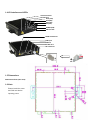
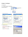
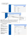
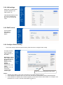
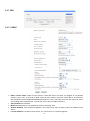
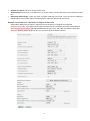
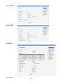
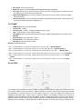
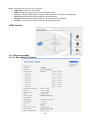
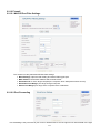
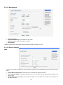
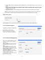
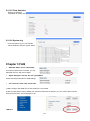
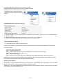
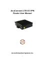
AcuConnect-LTE-V2 VPN Router User Manual Acura Embedded Systems Inc. 1 Content Chapter 1 Product Specification .....................................................................................3 1.1 Overview ...........................................................................................................3 1.2 Technical Support .............................................................................................3 1.3 Specification ......................................................................................................3 1.4 I/O Interface and LEDs ......................................................................................4 1.5 Dimensions .......................................................................................................5 1.6 Note ..................................................................................................................5 Chapter 2 Configure ....................................................................................................... 5 2.1 Connection ....................................................................................................... 5 2.1.1 Computer network configuration .............................................................. 5 2.1.2 Login the router ....................................................................................... 5 2.2 Configure Parameters ..................................................................................... ..6 2.2.1 Router webpage .................................................................................... ..6 2.2.2 Operation mode ..................................................................................... ..6 2.2.3 WAN settings......................................................................................... ..6 2.2.4 LAN settings .......................................................................................... ..7 2.2.5 DHCP clients ........................................................................................... 7 2.2.6 Configure Static Routing .......................................................................... 7 2.2.7 VPN ......................................................................................................... 8 2.2.8 DTU....................................................................................................... 10 2.2.9 SNMP .................................................................................................... 11 2.2.10 VRRP .................................................................................................. 11 2.2.11 Wireless settings ................................................................................. 12 2.2.12 Firewall ................................................................................................ 13 2.2.13 Administration ...................................................................................... 15 Chapter 3 FAQ ............................................................................................................. 18 2 Chapter 1 Product Specification 1.1 Overview ACUCONNECT-LTE router with 4G and WIFI provides users the high speed, always online and transparent data transmission communication network. Its reliable and standard industrial design meet the most of needs of Electronic Power System Automation, Industry Monitoring, Transportation Management, Weather, Environment Protection, Pipe Network Monitoring, Finance and Bond industries. 1.2 Technical Support To enable users to quickly solve problems encountered in the course, and get the right solution on hardware, operating system and installation, please contact technical support as follows. Telephone: 604.502.9666 Toll Free:1.866.502.9666 Email:[email protected] Website:www.acuraembedded.com 1.3 Specification • • • • • • • • • • • RAM:256Mbit ; FLASH:64Mbit Power Input : Input DC 7-36V, standard DC12V; Low-voltage, over current, over voltage, anti-reverse protection Environment: Storage Temperature:-40℃~70℃; Work Temperature:-30℃~60℃ Humidity:<95% Volume : L*W *H:105*105*26mm Weight : Net weight (no accessories):300g Data Interface: 1 x LAN 10/100Mb RJ45; 1 x Serial port RS232/485 1 x SIM card slot WIFI : Transmitting power: 17dbm Distance: cover a radius of 100 meters in open area test Allow 32 users to access in theory EMC: Electrostatic discharge immunity:EN6100-4-2,level 2 RFEMS: EN6100-4-3, level 2 Surge:EN6100-4-3, level 2 ; PFMF:EN6100-4-6, level 2 Shockwave immunity:EN6100-4-8, Horizontal / vertical direction 400A/m( >level 2) Physical property Shockproof:IEC60068-2-27 Drop test:IEC60068-2-32 Vibration test:IEC60068-2-6 3 1.4 I/O Interface and LEDs AUX Cell Antenna Reset Button Wi-Fi (LED) VPN (LED) LAN (LED) LTE (LED) POWER (LED) SIM Card Slot MAIN Cell Antenna UART port LAN Port DC IN 8~30 V Wi-Fi Antenna 1.5 Dimensions Dimensions Size (Unit: mm) 1.6 Note Please install the router and SIM card before inputting power. 4 Chapter 2 Configure 2.1 Connection 2.1.1 Computer network configuration Find “Local Area Connection”, and choose “Properties” Choose “Internet Protocol”, Choose automatically or input IP manually 2.1.2 Login the router Open the Web browser, and type http://192.168.8.1 into the address field and press Enter. Type User Name “admin” and Password “admin” in the pop-up 5 2.2 Configure Parameters 2.2.1 Router webpage 2.2.2 Operation mode NAT: Network Address Translation Note: The default setting is Gateway mode. Bridge: All Ethernet and wireless interfaces are bridged into a single bridge interface. Gateway: The first Ethernet port is treated as WAN port. The other Ethernet ports and the wireless interface are bridged together and are treated as LAN ports. AP Client: The wireless AP client interface is treated as WAN port and the wireless AP interface and the Ethernet ports are LAN ports. 2.2.3 WAN settings SIM PIN: enter PIN code if necessary. Operation Mode: always online, connect on demand, connect on time. The default mode is always on line. MSP Name: any name is ok Dialing Number: Input the Dialing Number you get from ISP. For example, Bell (*99#) APN(Access Point Name): This SIM Card APN name is from local ISP User Name: input it if ISP offers Password: input it if ISP offers Authenticate Type: PAP/CHAP/Auto 6 6 2.2.4 LAN settings Setting the LAN parameters, include IP address, sub mask, DHCP, etc LAN2 Default Gateway: Here you can set a different IP, with it you can access the router. 2.2.5 DHCP clients List the Clients which gain IP address from DHCP . 2.2.6 Configure Static Routing This section mainly introduces what is Routing Table and how to configure static routing. This page is about how to set static routing function of the router. Destination: Please enter Target Host or IP network segment Range: Host or Network can be chosen Gateway: IP address of the next router. Interface: You can choose the corresponding interface type. This is the key routing table of this router. Notice: • Gateway and LAN IP of this router must belong to the same network segment. • If the destination IP address is the one of a host, and then the Subnet Mask must be 255.255.255.255. • If the destination IP address is IP network segment, it must match with the Subnet Mask. For example, if the destination IP is 10.0.0.0, and the Subnet Mask is 255.0.0.0. 7 2.2.7 VPN 2.2.7.1 IPSEC • • • • • IPSec connect name: make sure the name in client and server are same, we suggest to use domain name(111.vpn1.com). if you want to build a point-to-point channel, the IPSec name have to be written as DEV+equipment ID+name(DEV281250D52F2A1452.vpn1.com), and make sure both the client and server are inputting Client equipment ID. You can find router’s ID in the Status interface. Service Mode: Server/Client Mode: Main/Aggressive. The Aggressive mode is commonly used. Remote Gateway: This choice just appears in the Client mode and it is used to fill the IP address in the Server. Local IP address: Fill LAN IP of this device. You can fill an IP or a network segment. 8 • • • Remote IP address: Fill the IP of the remote router. Authentication: Commonly, Pre-Shared Key is chosen. And the Client and Server must choose the same key. Advanced AKE settings: There are some encryption methods in this field. You must use the settings in this field when VPN tunnel needs to be built between client and other brand VPN server. Example: Connected Cisco 7200 How to configure as VPN client IPSec Name: Make sure the name in client and server are same, we suggest to use domain name(111.vpn1.com). if you want to build a point-to-point channel, the IPSec name has to be written as DEV +Equipment ID +Name (DEV281250D52F2A1452.vpn1.com), and make sure both the client and server are inputting Client equipment ID. You can find its ID in the Status interface. 9 2.2.7.2 PPTP 2.2.7.3 L2TP 2.2.8 DTU DTU settings. 10 • DTU status: open and close DTU • Baud rate: support 300/1200/4800/9600/19200/38400/57600/115200bps • Link Type: Server link or Client link can be chosen in the DTU configure table. If using it as Server, we suggest you to use fixed IP of the SIM card. • Multiple-path Backup: the router can support 4 Server IP at most to meet the need for multiplepath data backup. • Heart Beat function: You can define heart beat time and heat beat information. So that Server can use the heart beat information to identify DTU. 2.2.9 SNMP • SNMP Active: Open and close SNMP; • Contact Info:Setting • Contact name; Location:Setting installation location name; • User:Setting Public name; example: public; • Host/Subnet: Allow some subnet segment access this SNMP, Default Settings is any(0.0.0.0/0); • Writable • Security Mode: Just support this version; • Authentication: Just support this version ; • Encryption: Just support this version ; Attention: Important OID list: 1.3.6.1.4.1.2021.255.4.1.2.9.103.101.116.95.109.111.100.101.109.1 (Module Model) 1.3.6.1.4.1.2021.255.4.1.2.10.103.101.116.95.117.112.116.105.109.101.1(Systime up time) 1.3.6.1.4.1.2021.255.4.1.2.12.103.101.116.95.109.101.109.95.102.114.101.101. 1 (Memory Size) 1.3.6.1.4.1.2021.255.4.1.2.15.103.101.116.95.99.101.108.108.95.115.116.97.11 6.117.115.1(3G Status) 1.3.6.1.4.1.2021.255.4.1.2.15.103.101.116.95.108.50.116.112.95.115.116.97.11 6.117.115.1 (PPTP Status) 1.3.6.1.4.1.2021.255.4.1.2.15.103.101.116.95.112.112.116.112.95.115.116.97.1 16.117.115.1(L2TP Status) 2.2.10 VRRP The Virtual Router Redundancy Protocol (VRRP) is designed to eliminate the single point of failure inherent in the static default routed environment. VRRP specifies an election protocol that dynamically assigns responsibility for a virtual router to one of the VRRP routers on a LAN. The VRRP that controls the IP addresses associated with a virtual router is called the Master, and forwards packets sent to those IP addresses. When the Master becomes unavailable, a backup (called Slave) takes the place of the Master. VRRP provides a function similar to the proprietary protocols “Hot Standby Router Protocol (HSRP)” and “IP Standby Protocol (IPSTB)”. If the Master fails, the Backup begins to service traffic formerly handled by the 11 Master. This switchover occurs in 3 to 10 seconds. • VRRP Active: Check to enable VRRP • VRRP ID: Enter the Group ID for this set of redundant routers. • Priority: (1-255)In a VRRP group, the larger number is Master, the smaller is Slave(backup) • Interval Time: VRRP Enter the Advertisement interval(seconds) • Password: Enter the shared group password, or leave blank for no password. • Virtual IP: All hosts in the LAN are using this IP as default gateway. VRRP Solution: 2.2.11 Wireless settings 2.2.11.1 Basic Wireless Settings 12 The basic parameters of Wi-Fi setting. The Radio function enable and disable. The network mode supports 802.11 b/g/n (draft). Support multi-SSID up to 8. 2.2.11.2 Wireless Security/Encryption Settings The SSID select from multi-SSID setting. • Security mode include: disable, open, share, wep auto, WPA, wpa-psk, wpa2, wpa2-psk, wpapsk/wpa2-psk, wpa/wpa2, 802.1X. • Access policy: Set MAC list for access or block. 2.2.11.3 WDS WDS(Wireless Distribution System):The router supports Bridge and Repeater mode now. WDS may provide two modes of wireless access point-to-access point (AP-to-AP) connectivity: Wireless bridging: in which WDS APs communicate only with each other and don't allow wireless clients or stations (STA) to access them Wireless repeating: in which APs communicate with each other and with wireless STAs Encryption: WEP, TKIP and AES. 13 2.2.12 Firewall 2.2.12.1 MAC/IP/Port Filter Settings This section is mainly about MAC/IP/Port filter settings • Basic Settings: Open the filter setting and set the filtering principle. • MAC address: Fill the MAC address which needs to filter. • Destination IP: IP of the target computer( the computer which data packet will be sent to) • Destination Port Range: port range of target computer • Source Port Range: port range of the computer which sends data 2.2.12.2 Port Forwarding Port forwarding is the process that your router or firewall uses to sort the right kind of network data to the right 14 port. Computers and routers use ports as a way to organize network data. Different types of data, such as web sites, file downloads, and online games, are each assigned a port number. By using port forwarding, the router or firewall sends the correct data to the correct place. • Virtual Server Settings: open and close Settings. • IP address: fill the IP address of forwarding. • Port Range: fill the Port of forwarding. 2.2.12.3 DMZ Host In computer networking, DMZ is a firewall configuration for securing local area networks (LANs). DMZ Settings: open and close Settings. DMZ host IP Address: Please Enter the IP address of the computer which you want to set as DMZ host Note: When DMZ host is set, the computer is completely exposed to the external network, the firewall will not influence this host. 2.2.12.4 System Security Include Remote management, Ping from WAN Filter and SPI (State Packet Inspection). 2.2.13 Administration 15 2.2.13.1 Management • • • • Select Language Administrator Settings. The default both are admin. Web Port, default Port is 80, Support 1~65535. NTP Settings DDNS: support Dyndns.org/freedns.afraid.org/www.zoneedit.com/www.no-ip.com 2.2.13.2 Reboot settings ICMP This function will detect the status of 3G by ping and complete the corresponding actions according to the ping result. • • • Reboot When Network Error: Choose the box to start the net detection function. Check Method (PING): fill the server domain name or IP, and then click the Check button to detect if the fill-in is right. Check interval time (second): the interval time between the first detection and the second detection is 60-86400 seconds. 16 • • • Check Count: when ping detection arrives to default time, but still cannot access, then the router will reboot. Reboot Count before Sleep: when continuous reboot times arrive to default value, the router will enter sleeping mode. This setting is to prevent the router to reboot continuously when cannot ping access caused by service IP’s error. Sleep Time (minute): here to set sleeping time. When arrives, the router will start Ping check again. Note: This function will be only valid only in 3G permanent on-line and dialing according to the setting time, other modes do not work. Firstly you must detect if the filled-in server domain name or IP is valid. Reboot when timeout Timer (minute): input any number from 60 to1440, the router will reboot when arrives to default value. 2.2.13.3 Software upgrade Upgrade the firmware to obtain new functionality. It takes about 2 minutes. Please don’t move the router until it reboots automatically. 2.2.13.4 Parameter Management Here you can make a backup of current settings or restore previous settings of the router . Export settings: click ‘export’ to export configuration files and then select save path. Import settings: click ‘browse’, select previous backup configuration files and then click ‘Import’. Then all the previous settings will be recovered. Load Factory Defaults: click ‘Load Default’ then all settings will be restored to factory settings. This is not recommended, in order to avoid the loss of important parameters. 17 2.2.13.5 Flow Statistics Display the statistics information of system flow. 2.2.13.6 System log From the system log you can read the various situations after the system starts. Chapter 3 FAQ • SIM Card Status shows “Not Ready” It means the SIM card is not found, you can take SIM card out, and insert it again. • Signal Strength is normal, but can’t get WAN IP Check the APN parameters in WAN settings. • Can’t visit the router from remote side 1) Make a ping to the WAN IP to check whether it is successful. 2) We are using 80 as router’s default port, but some ISP block the 80 port, you can confirm with local ISP which ports are open, and change port to try. LAN fails 18 1) Check RJ45 cable, make sure it is correctly connected. 2) Make sure the PC and router are in same network segment. 3) Disable the PC network card, and re-enable it. 4) Reset the router. Press Reset button for several seconds, it will load to factory settings. Get WAN IP, but PC can’t access internet. 1) Check the DNS, you can make a ping to a normal IP (e.g. 8.8.8.8), if ping IP is ok, the question must be caused by DNS. 2) Make sure the SIM card support data service, you can try it in your cell phone. 3) Signal is too weak. Move antenna or change position to get better signal Port forwarding not working 1) Check with ISP which ports are open by them 2) More than 1 router. The most common problem we come across is people who are behind 2 or more routers and don’t realize it. So here is a quick step by step. Step 1. Login into your Router Step 2. Find the status page that shows the WAN/Internet IP address and write it down. Step 3. Log into the first router/modem now. Step 4. Find the DMZ page Step 5. Enter the IP you wrote down into the DMZ page and enable DMZ. Step 6. Save and your done. Thankfully it is easy to get port forwarding if this is happening. We simply tell the first router to send all incoming connections to the 2nd router where the port forwarding rules are. Serial port not working Problem (1): I can get heartbeat from client on the TCP Server, but PLC data can’t come Solution: check the baud rate of router and PLC, make sure their parameter settings are same. Problem (2): I can’t get heartbeat and PLC data from client on the TCP Server. Solution: check the TCP server and port, make sure they are allowed to visit. 19 With the unique set of products, Acura Embedded Systems remains committed to its goal of providing trouble-free and customer-friendly service. A special customer service unit has been set up specifically to cater to our esteemed customers' needs. Technical Support: North American Technical support contact your Salesperson Toll Free : 1-866-528-2214 [email protected] Mailing address: Acura Embedded Systems Inc. Unit #1, 7711-128th Street, Surrey, BC V3W 4E6, CANADA Ph: (604) 502-9666 Fax: (604) 502-9668 www.acuraembedded.com 20