1
Control-Soft Enterprises
Instrument and Control Software for the Process Industries
FE-Sizer
Version 3.0
For Windows95/98/NT/2000/xp
Flow Meter Sizing
© 1994-2010 Copyright Control-Soft Enterprises. All Rights Reserved
Licensed M aterial: Property of Control-Soft Enterprises
2319 M orning Park Drive, Katy, Texas 77494-2111, Phone (281) 217-6284 Fax (281) 395-5102
Control-Soft Enterprises
Instrument and Control Software for the Process Industries
Information in this document is subject to change without notice and does not represent a commitment on the part of
Control-Soft Enterprises. The software described in this document is furnished under a license agreement. It is unlawful
to copy this software on magnetic tape, disk, or any other medium for any purposes other than the purchaser's personal
use.
© 1994-2010 Control-Soft Enterprises. All Rights Reserved.
Third Party Copyrights: Integrated within FE-Sizer for W indows, Version 3.0 are the following products provided by
third parties, who own the copyrights to these products. The products are trademarks or trade names of their respective
owners:
Properties of Steam and W ater using the 1967 IPC Formulation for Industrial Use and other IAPW S releases Copyright
© 1993 by ASME. All rights reserved.
If you have comments about the software or this manual, please forward to Control-Soft Enterprises at:
Control-Soft Enterprises
2319 Morning Park Drive
Katy, Texas 77494-2111
Table of Contents
TABLE OF CONTENTS
1.
PROGRAM DESCRIPTION. . . . . . . . . . . . . . . . . . . . . . . . . . . . . . . . . . . . . . . . . . . . . . .
1.1
Introduction. . . . . . . . . . . . . . . . . . . . . . . . . . . . . . . . . . . . . . . . . . . . . . . . . . . . .
1.2
Meter Types. . . . . . . . . . . . . . . . . . . . . . . . . . . . . . . . . . . . . . . . . . . . . . . . . . . . .
1.3
Sizing Methods. . . . . . . . . . . . . . . . . . . . . . . . . . . . . . . . . . . . . . . . . . . . . . . . . .
1.4
Factors. . . . . . . . . . . . . . . . . . . . . . . . . . . . . . . . . . . . . . . . . . . . . . . . . . . . . . . . .
1.7
Units System. . . . . . . . . . . . . . . . . . . . . . . . . . . . . . . . . . . . . . . . . . . . . . . . . . . .
1.8
Record Keeping. . . . . . . . . . . . . . . . . . . . . . . . . . . . . . . . . . . . . . . . . . . . . . . . . .
1.9
Program Features. . . . . . . . . . . . . . . . . . . . . . . . . . . . . . . . . . . . . . . . . . . . . . . . .
1.10
Version 3.0 Enhancements.. . . . . . . . . . . . . . . . . . . . . . . . . . . . . . . . . . . . . . . . .
1
1
2
2
2
2
3
3
3
2.
PROGRAM INSTALLATION. . . . . . . . . . . . . . . . . . . . . . . . . . . . . . . . . . . . . . . . . . . . .
2.1
First Steps. . . . . . . . . . . . . . . . . . . . . . . . . . . . . . . . . . . . . . . . . . . . . . . . . . . . . .
2.2
The FE-Sizer Package. . . . . . . . . . . . . . . . . . . . . . . . . . . . . . . . . . . . . . . . . . . . .
2.3
Necessary Equipment. . . . . . . . . . . . . . . . . . . . . . . . . . . . . . . . . . . . . . . . . . . . .
2.4
Installing FE-Sizer. . . . . . . . . . . . . . . . . . . . . . . . . . . . . . . . . . . . . . . . . . . . . . . .
5
5
5
5
5
3.
DATA
3.1
3.2
3.3
3.4
3.5
3.6
3.7
3.8
3.9
4.
USER INTERFACE TYPES AND DESCRIPTIONS.. . . . . . . . . . . . . . . . . . . . . . . . . .
4.1
Main Screen. . . . . . . . . . . . . . . . . . . . . . . . . . . . . . . . . . . . . . . . . . . . . . . . . . . .
4.2
Menu Bar. . . . . . . . . . . . . . . . . . . . . . . . . . . . . . . . . . . . . . . . . . . . . . . . . . . . . .
4.2.1
File.. . . . . . . . . . . . . . . . . . . . . . . . . . . . . . . . . . . . . . . . . . . . . . . . . . .
4.2.2
Edit. . . . . . . . . . . . . . . . . . . . . . . . . . . . . . . . . . . . . . . . . . . . . . . . . . .
4.2.3
Tag. . . . . . . . . . . . . . . . . . . . . . . . . . . . . . . . . . . . . . . . . . . . . . . . . . .
4.2.4
Fluid. . . . . . . . . . . . . . . . . . . . . . . . . . . . . . . . . . . . . . . . . . . . . . . . . .
4.2.5
Sizing.. . . . . . . . . . . . . . . . . . . . . . . . . . . . . . . . . . . . . . . . . . . . . . . . .
4.2.6
Factors. . . . . . . . . . . . . . . . . . . . . . . . . . . . . . . . . . . . . . . . . . . . . . . . .
4.2.7
Meter/Pipe. . . . . . . . . . . . . . . . . . . . . . . . . . . . . . . . . . . . . . . . . . . . . .
4.2.8
Base.... . . . . . . . . . . . . . . . . . . . . . . . . . . . . . . . . . . . . . . . . . . . . . . . .
4.2.9
Utility. . . . . . . . . . . . . . . . . . . . . . . . . . . . . . . . . . . . . . . . . . . . . . . . .
4.2.10 W indow. . . . . . . . . . . . . . . . . . . . . . . . . . . . . . . . . . . . . . . . . . . . . . . .
4.2.11 View. . . . . . . . . . . . . . . . . . . . . . . . . . . . . . . . . . . . . . . . . . . . . . . . . .
4.2.12 Help. . . . . . . . . . . . . . . . . . . . . . . . . . . . . . . . . . . . . . . . . . . . . . . . . . .
4.3
Pop-up Menus. . . . . . . . . . . . . . . . . . . . . . . . . . . . . . . . . . . . . . . . . . . . . . . . . .
4.4
Drop-Down List Boxes. . . . . . . . . . . . . . . . . . . . . . . . . . . . . . . . . . . . . . . . . . .
4.5
Dialog Boxes. . . . . . . . . . . . . . . . . . . . . . . . . . . . . . . . . . . . . . . . . . . . . . . . . . .
4.6
Text Boxes.. . . . . . . . . . . . . . . . . . . . . . . . . . . . . . . . . . . . . . . . . . . . . . . . . . . .
4.7
Keyboard Shortcuts. . . . . . . . . . . . . . . . . . . . . . . . . . . . . . . . . . . . . . . . . . . . . .
4.8
Tool Bar.. . . . . . . . . . . . . . . . . . . . . . . . . . . . . . . . . . . . . . . . . . . . . . . . . . . . . .
4.9
Status Bar.. . . . . . . . . . . . . . . . . . . . . . . . . . . . . . . . . . . . . . . . . . . . . . . . . . . . .
REQUIREMENTS.. . . . . . . . . . . . . . . . . . . . . . . . . . . . . . . . . . . . . . . . . . . . . . . . 7
Symbols and Nomenclature. . . . . . . . . . . . . . . . . . . . . . . . . . . . . . . . . . . . . . . . . 7
Fluid Data. . . . . . . . . . . . . . . . . . . . . . . . . . . . . . . . . . . . . . . . . . . . . . . . . . . . . . 9
Sizing Data. . . . . . . . . . . . . . . . . . . . . . . . . . . . . . . . . . . . . . . . . . . . . . . . . . . . 10
Meter/Pipe Data. . . . . . . . . . . . . . . . . . . . . . . . . . . . . . . . . . . . . . . . . . . . . . . . . 10
Manometer Factor (F M). . . . . . . . . . . . . . . . . . . . . . . . . . . . . . . . . . . . . . . . . . . 11
Drain/Vent Hole Factor (F DH). . . . . . . . . . . . . . . . . . . . . . . . . . . . . . . . . . . . . . 11
W ater Vapor Correction Factor (F WV). . . . . . . . . . . . . . . . . . . . . . . . . . . . . . . . 11
Saturated Liquid Factor (F SAT). . . . . . . . . . . . . . . . . . . . . . . . . . . . . . . . . . . . . . 11
Vapor Quality Factor (F X). . . . . . . . . . . . . . . . . . . . . . . . . . . . . . . . . . . . . . . . . 11
I-1
13
13
13
14
14
14
15
15
15
15
15
15
16
16
16
16
17
17
17
19
20
21
FE-Sizer for W indows • Version 3.0
5.
FLOW METER SIZING. . . . . . . . . . . . . . . . . . . . . . . . . . . . . . . . . . . . . . . . . . . . . . . . .
5.1
Files. . . . . . . . . . . . . . . . . . . . . . . . . . . . . . . . . . . . . . . . . . . . . . . . . . . . . . . . . .
5.1.1
Project. . . . . . . . . . . . . . . . . . . . . . . . . . . . . . . . . . . . . . . . . . . . . . . . .
5.1.2
Calculation. . . . . . . . . . . . . . . . . . . . . . . . . . . . . . . . . . . . . . . . . . . . .
5.1.3
Datasheet. . . . . . . . . . . . . . . . . . . . . . . . . . . . . . . . . . . . . . . . . . . . . . .
5.1.4
Print. . . . . . . . . . . . . . . . . . . . . . . . . . . . . . . . . . . . . . . . . . . . . . . . . . .
5.1.5
Print Preview Pop-up Menu. . . . . . . . . . . . . . . . . . . . . . . . . . . . . . . .
5.1.6
Print Setup. . . . . . . . . . . . . . . . . . . . . . . . . . . . . . . . . . . . . . . . . . . . . .
5.1.7
Utilities Pop-up Menu. . . . . . . . . . . . . . . . . . . . . . . . . . . . . . . . . . . . .
5.1.8
Most Recent Files. . . . . . . . . . . . . . . . . . . . . . . . . . . . . . . . . . . . . . . .
5.1.9
Exit. . . . . . . . . . . . . . . . . . . . . . . . . . . . . . . . . . . . . . . . . . . . . . . . . . .
5.2
Edit. . . . . . . . . . . . . . . . . . . . . . . . . . . . . . . . . . . . . . . . . . . . . . . . . . . . . . . . . .
5.2.1
Copy Tag... Ctrl+C. . . . . . . . . . . . . . . . . . . . . . . . . . . . . . . . . . . . . . .
5.2.2
Paste Tag... Ctrl+V. . . . . . . . . . . . . . . . . . . . . . . . . . . . . . . . . . . . . . .
5.3
Tag.. . . . . . . . . . . . . . . . . . . . . . . . . . . . . . . . . . . . . . . . . . . . . . . . . . . . . . . . . .
5.3.1
Input Tag Data.. . . . . . . . . . . . . . . . . . . . . . . . . . . . . . . . . . . . . . . . . .
5.3.2
Retrieve Tag... Alt+R. . . . . . . . . . . . . . . . . . . . . . . . . . . . . . . . . . . . .
5.3.3
Save Tag...Ctrl+Alt+S. . . . . . . . . . . . . . . . . . . . . . . . . . . . . . . . . . . . .
5.3.4
Delete Tag... Alt+D. . . . . . . . . . . . . . . . . . . . . . . . . . . . . . . . . . . . . . .
5.4
Fluids. . . . . . . . . . . . . . . . . . . . . . . . . . . . . . . . . . . . . . . . . . . . . . . . . . . . . . . . .
5.4.1
Input Fluid Data.. . . . . . . . . . . . . . . . . . . . . . . . . . . . . . . . . . . . . . . . .
5.4.2
Calc Fluid Properties. . . . . . . . . . . . . . . . . . . . . . . . . . . . . . . . . . . . . .
5.4.3
Gases & Vapors.. . . . . . . . . . . . . . . . . . . . . . . . . . . . . . . . . . . . . . . . .
5.4.5
Liquid-Volume. . . . . . . . . . . . . . . . . . . . . . . . . . . . . . . . . . . . . . . . . .
5.5
Sizing. . . . . . . . . . . . . . . . . . . . . . . . . . . . . . . . . . . . . . . . . . . . . . . . . . . . . . . . .
5.5.1
Input Sizing Data. . . . . . . . . . . . . . . . . . . . . . . . . . . . . . . . . . . . . . . . .
5.5.2
Calculation Setup. . . . . . . . . . . . . . . . . . . . . . . . . . . . . . . . . . . . . . . .
5.6
Factors. . . . . . . . . . . . . . . . . . . . . . . . . . . . . . . . . . . . . . . . . . . . . . . . . . . . . . . .
5.6.1
Manometer Factor (F M). . . . . . . . . . . . . . . . . . . . . . . . . . . . . . . . . . . .
5.6.2
Drain/Vent Hole Factor (F DH). . . . . . . . . . . . . . . . . . . . . . . . . . . . . . .
5.6.3
W ater Vapor Correction Factor (F WV). . . . . . . . . . . . . . . . . . . . . . . . .
5.6.4
Saturated Liquid Factor (F SAT).. . . . . . . . . . . . . . . . . . . . . . . . . . . . . .
5.6.5
Vapor Quality Factor (F X). . . . . . . . . . . . . . . . . . . . . . . . . . . . . . . . . .
5.7
Meter/Pipe. . . . . . . . . . . . . . . . . . . . . . . . . . . . . . . . . . . . . . . . . . . . . . . . . . . . .
5.7.1
Meter Data.. . . . . . . . . . . . . . . . . . . . . . . . . . . . . . . . . . . . . . . . . . . . .
5.7.2
Pipe Data. . . . . . . . . . . . . . . . . . . . . . . . . . . . . . . . . . . . . . . . . . . . . . .
5.8
Base.... . . . . . . . . . . . . . . . . . . . . . . . . . . . . . . . . . . . . . . . . . . . . . . . . . . . . . . .
5.9
Utility.. . . . . . . . . . . . . . . . . . . . . . . . . . . . . . . . . . . . . . . . . . . . . . . . . . . . . . . .
5.9.1
Flow Units Setup. . . . . . . . . . . . . . . . . . . . . . . . . . . . . . . . . . . . . . . . .
5.9.2
User Data.. . . . . . . . . . . . . . . . . . . . . . . . . . . . . . . . . . . . . . . . . . . . . .
5.9.3
Uncertainty.... . . . . . . . . . . . . . . . . . . . . . . . . . . . . . . . . . . . . . . . . . . .
5.10
W indow. . . . . . . . . . . . . . . . . . . . . . . . . . . . . . . . . . . . . . . . . . . . . . . . . . . . . . .
5.11
View. . . . . . . . . . . . . . . . . . . . . . . . . . . . . . . . . . . . . . . . . . . . . . . . . . . . . . . . .
5.12
Help. . . . . . . . . . . . . . . . . . . . . . . . . . . . . . . . . . . . . . . . . . . . . . . . . . . . . . . . . .
6.
FE-Sizer TUTORIAL. . . . . . . . . . . . . . . . . . . . . . . . . . . . . . . . . . . . . . . . . . . . . . . . . . . 53
6.1
Setting Up the Project Database. . . . . . . . . . . . . . . . . . . . . . . . . . . . . . . . . . . . 53
6.2
Calculating the Sizing Parameter. . . . . . . . . . . . . . . . . . . . . . . . . . . . . . . . . . . . 56
I-2
23
23
24
27
27
27
29
30
30
31
31
31
31
31
31
31
32
32
32
32
33
33
33
34
35
35
35
36
36
37
38
40
40
41
41
47
48
49
49
49
50
51
52
52
Table of Contents
7.
DATA
7.1
7.2
7.3
SHEET ENTRY.. . . . . . . . . . .
Datasheet Entry - Part 1 of 3.
Datasheet Entry - Part 2 of 3.
Datasheet Entry - Part 3 of 3.
.
.
.
.
...
...
...
...
...
...
...
...
.
.
.
.
.
.
.
.
.
.
.
.
.
.
.
.
.
.
.
.
.
.
.
.
.
.
.
.
.
.
.
.
.
.
.
.
.
.
.
.
.
.
.
.
.
.
.
.
.
.
.
.
.
.
.
.
.
.
.
.
.
.
.
.
.
.
.
.
.
.
.
.
.
.
.
.
...
...
...
...
...
...
...
...
.
.
.
.
.
.
.
.
.
.
.
.
.
.
.
.
.
.
.
.
.
.
.
.
8.
DATA IMPORTING AND EXPORTING. . . . . . . . . . . . . . . . . . . . . . . . . . . . . . . . . . . 65
9.
FLUID
9.1
9.2
9.3
PROPERTY CORRELATIONS. . . . . . . . . . . . . . . . . . . . . . . . . . . . . . . . . . . . .
Single Component & Multi-Component Fluid Selection Dialog. . . . . . . . . . . .
Fluid Properties - Pressure and/or Temperature Data Dialog. . . . . . . . . . . . . .
Equations-of-State. . . . . . . . . . . . . . . . . . . . . . . . . . . . . . . . . . . . . . . . . . . . . . .
61
61
62
63
85
85
87
87
APPENDIX A - W ARNING MESSAGES. . . . . . . . . . . . . . . . . . . . . . . . . . . . . . . . . . . . . . . . . A-1
APPENDIX B - ERROR MESSAGES. . . . . . . . . . . . . . . . . . . . . . . . . . . . . . . . . . . . . . . . . . . . B-1
APPENDIX C - PROGRAM EQUATIONS. . . . . . . . . . . . . . . . . . . . . . . . . . . . . . . . . . . . . . . . C-1
I-3
FE-Sizer for W indows • Version 3.0
I-4
Section 1 - Program Description
1.
PROGRAM DESCRIPTION
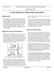
1.1
Introduction
FE-Sizer is a valuable engineering tool for sizing and selecting head-type flow meters in
closed conduits. It is flexible, easy-to-use, and complete with appropriate menus and lists.
The software includes meter selection, material tables and pipe data tables. A table of
standard drain and vent hole diameters are available where the user selects the hole
diameter to calculate the drain/vent hole correction factor, F DH. These factors aid the user
in selecting the proper meter application. Extensive built-in warnings flag potential
application and data entry errors.
The program equations, methods and procedures comply with the following standards
governing the sizing and specification of head-type orifice meter devices:
•
ASME MFC-3M-1989 and ASME MFC-3M-2004 — Measurements of Fluid Flow
in Pipes Using Orifice, Nozzle and Venturi
•
ASME MFC-14M-2003 — Measurements of Fluid Flow Using Small Bore Precision
Orifice Meters
•
ANSI/API 2530-AGA Report No. 3 (both 1985 and 1992 versions) — Orifice
Metering of Natural Gas and Other Related Hydrocarbon Fluids - Part 3 Natural
Gas Applications
•
ISO-5167 (1991) — Measurement of Fluid Flow by Means of Pressure Differential
Devices — Part 1: Orifice Plates, Nozzles and Venturi Tubes Inserted in Circular
Cross-section Conduits Running Full.
•
ISO-5167-2 (2003) — Measurement of fluid flow by means of pressure differential
devices — Part 2: Orifice plate
•
ISO-5167-3 (2003) — Measurement of fluid flow by means of pressure differential
devices — Part 3: Nozzles and Venturi nozzles.
•
ISO-5167-4 (2003) — Measurement of fluid flow by means of pressure differential
devices — Part 4: Venturi tubes
•
ISO/TR 15377 — Measurements of Fluid Flow by Means of Pressure-Differential
Devices - Guidelines for the Specification of Orifice Plates, Nozzles and Venturi
Tubes Beyond the Scope of ISO 5167
Sizing methods use the iterative procedure described in R. W . Miller's, Flow
Measurement Engineering Handbook, Third Edition, McGraw-Hill Publishing Company.
The discharge coefficient correlations include those above for their applicable flow
devices. For all other meter types the discharge coefficient correlations are from the
ASME standard and R. W . Miller's handbook.
1
FE-Sizer for W indows • Version 3.0
1.2
M eter Types
FE-Sizer allows the user to select from the following orifice meter types:
•
•
•
•
•
•
Orifice Plates: Concentric, segmental, eccentric, integral, honed small-bore pipe,
quadrant, and conic style orifice plates.
Flow Nozzles: ASME long radius, ASME throat tap, ISA nozzle, and Venturi nozzle
with ISA inlet.
Venturi tubes: Machined inlet, rough cast inlet, and rough sheet metal fabricated
construction with either 7-degree or 15-degree outlet cones.
Universal Venturi Tubes.
Lo-Loss Tubes.
W edge Meters.
In addition, the user may enter custom calibrated discharge coefficients for calculating
bores, flows, and differential pressures of custom or calibrated meter run applications.
1.3
Sizing M ethods
FE-Sizer calculates the required orifice bore, flow, or differential pressure for the
following fluid types:
•
•
•
•
Ideal and non-ideal gases – volumetric flow.
Vapors – mass flow.
Viscous and non-viscous liquids – volumetric flow.
Viscous and non-viscous liquids – mass flow.
Gas and vapor sizing equations may be either Pressure-Volume-Temperature (PVT) or
Density form. Liquid flow sizing equations may be Specific Gravity or Density form. FESizer includes "critical-drop" flow and bore formulas for sizing restrictive flow devices
for gas, vapor and liquid fluids.
1.4
Factors
FE-Sizer includes special sizing factors important for flow meter corrections. Factors
included in FE-Sizer are:
•
•
•
•
•
Manometer correction.
Drain and vent hole correction.
W ater vapor correction.
Two phase flows – saturated liquid (0.0%-10.0% vapor mass to total mass content).
Two phase flows – saturated vapor (90.00% -99.99% vapor mass to total mass
content).
The factors correct the calculated bore, flow or differential pressure for specific
applications.
1.7
Units System
FE-Sizer includes a completely selectable units system through pulldown selection lists
that allows the user to change units "on the fly" for any calculated or input variable.
2
Section 1 - Program Description
1.8
Record Keeping
FE-Sizer allows user to print calculation sheets, data sheets, calibration charts, or meter
system uncertainty calculations from an easy-to-use menu system. FE-Sizer saves data
records in a retrievable electronic format so future updates to the orifice sizing
calculations and data sheets can be made simply and easily. Data records are retrieved
using a built-in tag/data listing of the stored information.
1.9
Program Features
•
•
•
•
•
•
•
1.10
Project database and management utilities for segregation of calculations by projects.
Batch print of calculations, data sheets, calibration charts and uncertainty charts for
projects.
ASCII comma separated value (CSV) project file import and export to interface FESizer with existing project databases.
Batch calculation mode for automatic sizing of flow elements from fluid data
imported from an external database.
ASME steam and water property data correlations using the equations defined by
1967 IPC Formulation for Industrial Use.
Built-in fluid properties database which includes fluid property correlations for liquid
and gases for over 300 fluids.
Flow meter index printout from within a project database.
Version 3.0 Enhancements
The FE-Sizer Flow Meter Sizing software package has many new features that improve
the performance of FE-Sizer. Some of the features include:
•
•
•
•
•
•
True 32-bit W indows operating system application.
Support for long filenames.
Selectable fonts and margins for hardcopy output.
Detection of cavitation and flashing conditions for liquid flow meter and pressure
restriction sizing.
User definable margins for metric paper support.
Easier and more flexible units system allows user to set units for individual
calculations instead of an entire project file.
3
FE-Sizer for W indows • Version 3.0
4
Section 2 - Program Installation
2.
PROGRAM INSTALLATION
2.1
First Steps
Before you begin working with FE-Sizer:
1)
2)
3)
2.2
Read your software license agreement.
Check the contents of your package.
Make sure you have the necessary equipment to run the program.
The FE-Sizer Package
Your FE-Sizer package includes the following:
1)
2)
3)
4)
This User's Guide.
5-1/4 inch CD-Rom program disk.
The Control-Soft license agreement.
The Control-Soft software registration card.
Insure that you have everything listed above. Advise Control-Soft immediately if anything
is missing.
2.3
Necessary Equipment
FE-Sizer requires the following minimum configuration to run properly:
1)
2)
3)
4)
2.4
An IBM ® Personal Computer or true compatible.
Microsoft W indows® 95, W indows® 98, W indows®NT, W indows®2000,
W indows® XP, W indows® 2003 Server, or W indows Vista 32-bit (will also work with
W indows Vista 64-bit in X86 compatibility mode).
One CD-Rom drive.
IBM ® or compatible VGA or SVGA monitor.
Installing FE-Sizer
To get FE-Sizer up and running on your PC, follow the following steps. For example,
assuming your CD-Rom drive designation is drive D,
1.
Insert the FE-Sizer setup disk into drive D. The setup program should start
automatically. Follow the onscreen instructions to complete the installation.
2.
If the setup utility does not start automatically after inserting into the CD-Rom drive
you may have Auto-Run disabled on your machine. If so, activate the W indows start
bar, choose the Run command.
3.
Type d:setup.exe and press enter (or use the browse button to select the setup.exe file
by double-clicking on it). Follow the onscreen instructions to complete the
installation.
5
FE-Sizer for W indows • Version 3.0
The install program does the following:
•
Creates one or more directories on your hard disk and copies the contents of the FESizer program disk onto them.
•
Creates a W indows application group and installs all FE-Sizer file icons there.
6
Section 3 - Data Requirements
3.
DATA REQUIREM ENTS
3.1
Symbols and Nomenclature
Symbol Description
C
C4
d(ref)
d DH
dP
dP m
dP n
D(ref)
Db
Dc
Df
D f1
D f2
DF
D GAS
D LIQUID
DM
D TP
E
F aD
F ad
F DH
FL
Fm
Fp
F SAT
F TP
F WV,dry
FX
Gb
Gf
Gg
HS
k
K
K0
MW
P atm
Pb
P f1
Discharge coefficient, true flow rate divided by the theoretical flow rate.
Discharge coefficient at an infinite Reynolds number.
Bore of head-type flow meter measured at 68EF (20EC).
Diameter of a drain or vent hole.
Differential pressure across the meter.
Differential pressure across the meter measured at maximum flow.
Differential pressure across the meter measured at normal flow.
Internal pipe diameter measured at 68EF (20EC).
Density at base conditions:
Liquids, 60EF (15.6EC) and 14.7 psia (101.3 kPa);
Gases, 60EF (15.6EC) and 14.69595 psia (101.325 kPa), or other base values.
Diameter of circle containing the segment of a segmental orifice.
Density of a liquid at flowing temperature.
Density of a gas or vapor at upstream-tap flowing conditions.
Density of a gas or vapor at downstream-tap flowing conditions.
Density of liquid at flowing conditions, uncorrected for pressure.
Density of gas or vapor portion of a two-phase liquid/vapor fluid.
Density of liquid portion of a two-phase vapor/liquid fluid.
Manometer-fluid density.
Effective or homogeneous density of a two-phase fluid.
Velocity-of-approach factor for Buckingham Flow Coefficient Correlation.
Thermal expansion factor for the pipe.
Thermal expansion factor for the flow meter.
Drain (gases or vapors) or vent (liquids) hole correction factor.
Local gravity correction factor.
Manometer correction factor.
Correction for liquid compressibility, D f / D F (usually 1.0 except at very high
pressures).
Correction for saturated liquid (two-phase flow) conditions.
Factor correcting static pressure to total pressure for critical drop sizing of gases
and vapors.
Correction for wet-gas volume or mass to dry-gas volume or mass.
W et-steam or wet-vapor quality correction factor.
Liquid base specific gravity with respect to water at 60EF.
Liquid flowing specific gravity at flowing temperature.
Gas or Vapor specific gravity (M w gas / M w air).
Segmental orifice plate height.
Ideal gas isentropic exponent or specific heat ratio (Cp/Cv).
Flow coefficient, K = C / [ 1 - b 4 ] ½.
Flow coefficient including velocity of approach at a hypothetical Reynolds
number of infinity.
Molecular weight.
Annual average barometric (atmospheric) pressure for a given geographic
location.
Base absolute pressure for gas volume flows.
Absolute static pressure at upstream-tap flowing conditions.
7
FE-Sizer for W indows • Version 3.0
P f2
Absolute static pressure at downstream-tap flowing conditions.
P WV Absolute pressure of water vapor in gas-water vapor mixture.
Pv
Vapor pressure of liquid at flowing temperature.
q
Gas or liquid volumetric flow rate at actual (flowing) conditions.
qm
Gas or liquid maximum volumetric flow rate at actual (flowing) conditions.
qn
Gas or liquid normal volumetric flow rate at actual (flowing) conditions.
Q
Gas or liquid volumetric flow rate at base conditions.
Qm
Gas or liquid maximum volumetric flow rate at base conditions.
Qn
Gas or liquid normal volumetric flow rate at base conditions.
Rd
Reynolds number of the meter bore.
RD
Reynolds number of the pipe.
Tb
Base absolute temperature for gas volume flows.
T f1
Temperature of gas, vapor or liquid at upstream-tap flowing conditions.
T f2
Temperature of gas, vapor or liquid at downstream-tap flowing conditions.
TF
Temperature at flowing conditions in degrees Fahrenheit.
U
Absolute viscosity of gas, vapor or liquid.
x
Quality or mass percent of vapor mass portion to total mass portion of a twophase fluid.
X1
Pressure ratio at the upstream tap pressure of the orifice, dP/P f1.
X2
Pressure ratio at the downstream tap pressure of the orifice, dP/P f2.
W
Vapor or liquid mass flow rate.
Wm
Vapor or liquid maximum mass flow rate.
Wn
Vapor or liquid normal mass flow rate.
Y
Gas expansion factor.
Y CR
Critical flow function for critical drop sizing of vapors.
Y1
Gas expansion factor at the upstream tap pressure of the orifice.
Y2
Gas expansion factor at the downstream tap pressure of the orifice.
Zb
Gas or vapor compressibility factor at base temperature and pressure.
Z f1
Gas or vapor compressibility factor at upstream-tap flowing conditions.
Z f2
Gas or vapor compressibility factor at downstream-tap flowing conditions.
áP
Thermal-expansion coefficient for pipe material.
á PE
Thermal-expansion coefficient for primary-element material.
â
Beta ratio, d/D.
âC
Segment beta ratio for a segmental orifice, â / 0.98.
SUBSCRIPTS:
1
b
m
upstream-tap condition.
base condition.
maximum condition.
2
f
n
8
downstream-tap condition.
flowing condition.
normal condition.
Section 3 - Data Requirements
3.2
Fluid Data
Table 3-1 shows the required fluid data for each fluid type. FE-Sizer requires an input for
all required data before sizing the flow meter for the given application.
Table 3-1
FLUID DATA
Fluid
Unit
Equation
Condition
Required Data
Base
M W or G g, Z b, Z f1 or Z f2, P f1 or P f2, T f1 or T f2,
U, k
Flowing
M W or G g, Z f1 or Z f2, P f1 or P f2, T f1 or T f2, U, k
Base
D b, D f1 or D f2, P f1 or P f2, T f1 or T f2, U, k
Flowing
D f1 or D f2, P f1 or P f2, T f1 or T f2, U, k
Vapor
Mass
PVT
Flowing
M W, Z f1 or Z f2, P f1 or P f2, T f1 or T f2, U, k
Vapor
Mass
Density
Flowing
D f1 or D f2, P f1 or P f2, T f1 or T f2, U, k
Base
G b, G f, P f1 or P f2, T f1 or T f2, U, F p
Flowing
G f, P f1 or P f2, T f1 or T f2, U, F p
Base
D b, D f, P f1 or P f2, T f1 or T f2, U, F p
Flowing
D f, P f1 or P f2, T f1 or T f2, U, F p
Liquid
Mass
SG
Flowing
G f, P f1 or P f2, T f1 or T f2, U, F p
Liquid
Mass
Density
Flowing
D f, P f1 or P f2, T f1 or T f2, U, F p
Gas
Volume
PVT
Gas
Volume
Density
Liquid
Volume
SG
Liquid
Volume
Density
Notes:
PVT - Pressure-Volume-Temperature Ideal-Gas Equation.
SG - Specific Gravity Liquid Equation.
Data can be at either upstream-tap condition (1) or downstream-tap condition (2). You cannot mix
conditions in a calculation.
9
FE-Sizer for W indows • Version 3.0
3.3
Sizing Data
Table 3-2 gives the sizing data for each fluid type. All required data must be entered
before you can calculate the sizing parameter.
Table 3-2
SIZING DATA
Fluid
Condition
Base
Gas
Vapor
Flowing
Flowing
Base
Liquid
Flowing
Mass
Notes:
3.4
Sizing Parameter
Required Data
d & dP n
Q m, Q n, dP m
Qm & Qn
dP m, dP n, d
dP m & dP n
Q m, Q n, d
d & dP n
q m, q n, dP m
qm & qn
dP m, dP n, d
dP m & dP n
q m, q n , d
d & dP n
W m, W n, dP m
Wm & Wn
dP m, dP n, d
dP m & dP n
W m, W n, d
d & dP n
Q m, Q n, dP m
Qm & Qn
dP m, dP n, d
dP m & dP n
Q m, Q n, d
d & dP n
q m, q n, dP m
qm & qn
dP m, dP n, d
dP m & dP n
q m, q n, d
d & dP n
W m, W n, dP m
Wm & Wn
dP m, dP n, d
dP m & dP n
W m, W n, d
To calculate sizing parameter for a single condition, i.e., maximum condition = normal condition,
set values for data for the maximum condition equal to the data for the normal condition.
M eter/Pipe Data
•
•
•
•
•
•
•
•
Meter type, e.g., orifice, venturi, nozzle, etc.
Meter style, e.g., concentric, segmental, etc.
Tap style, e.g., flange taps, pipe taps, etc.
Meter material.
Nominal pipe diameter.
Pipe schedule.
Pipe inner diameter.
Pipe material.
10
Section 3 - Data Requirements
3.5
M anometer Factor (F M)
C
C
C
3.6
Drain/Vent Hole Factor (F DH)
C
3.7
W ater vapor pressure at the flowing temperature.
Saturated Liquid Factor (F SAT)
C
C
3.9
Diameter of drain or vent hole (d DH).
W ater Vapor Correction Factor (F WV)
C
3.8
Temperature of seal fluid at meter.
Density of seal fluid at meter.
Local acceleration of gravity.
Density of gas or vapor portion (D GAS).
Quality or mass percent of vapor portion to total portion (x: 0.0% < x < 10.0%).
Vapor Quality Factor (F X)
C
C
Density of liquid portion (D LIQUID).
Quality or mass percent of vapor portion to total portion (x: 50.0% < x < 99.99%).
11
FE-Sizer for W indows • Version 3.0
12
Section 4 - User Interface Types and Descriptions
4.
USER INTERFACE TYPES AND DESCRIPTIONS
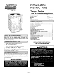
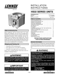
4.1
M ain Screen
The Flow M eter Sizing screen or sizing screen shown in Figure 4-1 displays all pertinent
data required to size flow orifices for a given fluid type. FE-Sizer divides this screen into
six sections with the following subtitles:
•
•
•
•
•
•
Fluid Data.
Sizing Data.
Factors.
Meter/Pipe
Data.
Base
Conditions.
Calculated
Results.
These sections
organize all data
into discrete
segments to
facilitate viewing
all the data
required to size a
flow meter. The
single screen
format eliminates
paging through
multiple screens
to check fluid data and meter information.
4.2
Figure 4-1
M enu Bar
At the top of the main screen illustrated in Figure 4-1 is a menu bar that lists the names
(titles) of the available menus within FE-Sizer. The menu bar arranges the menu titles by
category or specific function. The brief description for each title category and the
respective pull-down menu items are:
File - basic file and print commands for creating, opening, printing and closing
project databases as well as various database maintenance utilities.
Edit - for copying and pasting tag data with a project database or between project
databases.
Tag - for accessing individual tag records within a project database.
Fluids - for setup of fluids and entering fluid data either manually or via property
correlations.
Sizing - for setup of sizing calculations and entering sizing data.
Factor - menu of available correction factors.
M eter/Pipe - for selecting among various meter styles and setup dialog for pipe data.
Base... - activates dialog to set base condition data, i.e., base temperature and
pressure, atmospheric pressure, etc.
13
FE-Sizer for W indows • Version 3.0
Utility - access various utility functions, i.e., flow units setup, user data - company
and customer, or uncertainty calculation settings.
W indow - access various views available for FE-Sizer, i.e., arrange windows, icons,
etc.
View - used to display/hide the toolbar and status bar.
Help - access the context sensitive on-line help, display FE-Sizer About dialog for
program information..
Detailed descriptions of each menu item are given in the following sections.
4.2.1
File
Project - pop-up menu where you select to create (new), open, close, save or delete
project databases or select to import/export ASCII delimited data from an opened
project database.
Calculation - pop-up menu where you select to perform a batch calculation on an
opened project or to clear all data for the current tag record.
Datasheet - pop-up menu to enter data sheet data or clear data sheet data for the
current tag record.
Print - pop-up menu for printing calculation sheets, data sheets, uncertainty
calculations, calibration charts or to batch print calculation sheets, data sheets, or tag
indices.
Print Preview - pop-up menu for previewing calculation sheets, data sheets,
uncertainty calculations, calibration charts or to batch print calculation sheets, data
sheets, or tag indices prior to printing to a printer.
Print Setup... - activates the printer setup dialog box for setting various printer
parameters.
Set Printer Font - activates the font selection dialog box for selecting the print font
for the program output.
Page Setup - dialog box for setting the page margins - left and right, top and bottom
- and the line spacing for printing calculations, data sheets, etc.
Utilities - pop-up menu for maintaining project databases, i.e., packing and reindexing a project database.
M ost Recent Files List - dynamic menu area that lists the most recent project files
accessed.
Exit - Exits FE-Sizer.
4.2.2
Edit
Copy - copies the current project tag record to memory for pasting between projects.
Paste - pastes the current tag record from memory into the selected project.
4.2.3
Tag
Input Tag Data - sets input focus to the first item for tag number in the tag data area
underneath the tool bar.
Retrieve Tag... - retrieves a tag record from a project database - grayed or disabled
until a project database is opened.
Save Tag... - save a tag record to a project database - grayed or disabled until a
project database is opened.
Delete Tag... - deletes a tag record from a project database - grayed or disabled until
a project database is opened.
Save Tag to File... - saves tag data as individual tag file - grayed or disabled until a
valid tag calculation file exists and sizing parameter calculated.
Retrieve Tag from File... - retrieves tag data from an individual tag file.
14
Section 4 - User Interface Types and Descriptions
4.2.4
Fluid
Input Fluid Data - sets input focus to the first item of the Fluid Data section of the
main screen.
Calculate Fluid Properties... - pop-up menu for selecting the fluid correlation used
to estimate the fluid properties.
Gases & Vapors - dialog to setup sizing equation for gas and flows.
Liquids - dialog to setup sizing equation for liquids.
4.2.5
Sizing
Input Sizing Data - sets input focus to first item of the Sizing Data section of the
main screen.
Calculation Setup... - dialog to select the sizing parameter and calculation modes.
Calculate Sizing Parameter - command to calculate sizing parameter based on user
supplied input data.
4.2.6
Factors
M anometer... - dialog for setup of factor for correcting the indicated differential for
the effects of a gas or liquid leg of fluid at static pressure and temperature at the
instrument for mercury U-tube manometers and mercury-manometer-type differential
pressure instruments.
Drain/Vent Hole... - dialog for setup of factor adjusting the calculation for the
increased flow through a drain or vent hole.
W ater-Vapor Correction... - dialog for setup of factor converting a given volume of
gas flow to a condition of moisture content other than that corresponding to flowing
conditions - enabled only for gases and vapors; grayed or disabled for any other fluid.
Saturated Liquid... - dialog for setup of factor correcting calculation for saturated
liquid flows where the vapor quality (percentage of vapor mass to total fluid mass) is
10 percent or less - enabled for all liquids; grayed or disabled for all gases and vapor
fluids.
Quality... - dialog for setup of factor correcting calculation for saturated vapor flows
where the vapor quality is 90 percent or more - enabled vapor mass flow fluids;
grayed or disabled for all other fluids.
4.2.7
M eter/Pipe
M eter Type - pop-up menu for selecting meter type, e.g., orifice, flow nozzle,
venturi, etc.
Pipe Data... - dialog for setup of pipe data, i.e., inner diameter, schedule, etc.
4.2.8
Base...
Activates dialog to set base condition data, i.e., base temperature and pressure,
atmospheric pressure, etc.
4.2.9
Utility
Flow Units Setup - dialog for setting and defining various flow units.
User - pop-up menu where you can select to enter user, company and customer data.
Uncertainty... - dialog for setting and defining the various uncertainty or accuracy
input values.
15
FE-Sizer for W indows • Version 3.0
4.2.10
W indow
Cascade - arrange windows as overlapped.
Tile - arrange windows as side-by-side.
Arrange Icons - arrange minimized window icons.
4.2.11
View
Tool Bar - view/hide toolbar graphic below the main menu bar.
Status Bar - view/hide status bar at the bottom of the main screen.
4.2.12
Help
FE-Sizer Help Contents - opens the FE-Sizer Help system contents.
FE-Sizer Help - opens the FE-Sizer Help system at the top-level Index screen.
About FE-Sizer - displays a dialog box that shows software version and registered
owner.
4.3
Pop-up M enus
Several of the
menu bar menu
items open a
pop-up menu for
making
additional
selections. Figure
4-2 gives an
example of a
pop-up menu list.
You choose an
item from a menu
list by moving
the mouse until
the pointer points
to the menu item
you want and
clicking the left
mouse button to
select.
Alternatively,
Figure 4-2
you can hold the
left mouse button down while dragging the selection cursor down the menu list releasing
the mouse button once the desired item is highlighted.
16
Section 4 - User Interface Types and Descriptions
4.4
Drop-Down List Boxes
FE-Sizer uses drop-down list
boxes for selecting additional
features or options. Figure 4-3
gives an example of a dropdown list for Plate Material
Selection to select the material
for an orifice plate. A dropdown list box appears initially
as a rectangular box containing
the current selection. W hen
you select the down arrow in
the square box at the right, a
list of available choices
appears. If there are more
items than can fit in the box,
scroll bars are provided. To
use the scroll bar, click the up
or down arrow, or drag the
scroll box until the item you
want to select is displayed.
4.5
Figure 4-3
Dialog Boxes
Sometimes, invoking a menu command activates a dialog box. An ellipsis (...) after a
menu command indicates that a dialog box will appear when you choose that command.
FE-Sizer uses dialog boxes to
enter data, such as printer
commands, user data, etc.
Figure 4-4 shows an example
of the dialog box opened for
printer setup from the File
menu. Often you need to move
within a dialog box to select
one or more options. The
currently selected option is
marked by the selection cursor,
which appears as a dotted
rectangle, a highlight, or both.
To move within a dialog box,
click the option or area you
Figure 4-4
want to move to. Or press TAB
to move clockwise or SHIFT+TAB to move counterclockwise through the options or
areas. If the option, box, or button has an underlined letter in its name, you can choose
that item by pressing and holding down the ALT key while typing the underlined letter.
4.6
Text Boxes
FE-Sizer uses text boxes or edit boxes to enter text or numeric data. Text boxes appear in
dialog boxes or in the various sections of the main screen. W hen you move to an empty
text box, an insertion point (a flashing vertical bar) appears. The text you type starts at the
17
FE-Sizer for W indows • Version 3.0
insertion point. If the box you move to contains text or numeric data, and the data is
highlighted, any key you type will replace it. Refer to Section 4.7 for more information
regarding editing keys for input fields.
18
Section 4 - User Interface Types and Descriptions
4.7
Keyboard Shortcuts
Key
Function
Alt+C
Closes a project database.
Alt+D
Deletes a tag record from the project database via the Project Tag
Selection dialog.
Alt+R
Retrieves a tag record from the project database via the Project Tag
Selection dialog.
Ctrl+Alt+C
Clears current calculation data from memory and screen.
Ctrl+Alt+D
Clears all datasheet data for the current tag number record without
deleting the calculation data.
Ctrl+Alt+S
Refreshes current project settings to the active project database file.
Ctrl+Alt+V
Previews current calculation sheet for printing.
Ctrl+B
Automatic batch calculation for all records within a project database.
Ctrl+C
Copies current tag record into memory for pasting into another file.
Ctrl+D
Activates Part 1 of datasheet entry dialog.
Ctrl+E
Exports project records to an ASCII delimited data file via the Export
Project dialog box.
Ctrl+I
Imports project records from an ASCII delimited data file via the
Import Project dialog box.
Ctrl+N
Creates a new project database file via the New Project File dialog.
Ctrl+O
Opens a project database file via the Project Open dialog.
Ctrl+P
Activates the Print dialog box to print the current calculation.
Ctrl+S
Saves current tag record data to project database.
Ctrl+V
Pastes calculation data previously copied to memory into the current
calculation.
19
FE-Sizer for W indows • Version 3.0
4.8
Tool Bar
The Tool Bar, illustrated above, is the graphic icon bar found underneath the FE-Sizer Menu Bar.
Moving the mouse over one of the icons and clicking the left mouse button activates a given task.
Note that the above example shows the Critical Drop Orifice Plate and Critical Drop Nozzle icons
as disabled as the current sizing mode is for flow meter sizing. Should the current sizing mode be
set to a critical drop sizing selection, these items would be enabled and the flow meter sizing
selections would be disabled.
The available tasks from the Tool Bar and their associated section reference number in
the manual are as follows...
Open project database - Section 5.1.1
Define customer data.
Clear all data from current screen.
Copy current tag record to memory - Section 5.2.1
Paste tag record from memory to current project- Section 5.2.2
Preview output for the current calculation - Section 5.14
Print the current calculation - Section 5.1.4
Retrieve tag record from project database - Section 5.3.2
Save tag record to project database - Section 5.3.3
Orifice plate data - Section 5.7.1
Flow nozzle data - Section 5.7.1
Venturi data - Section 5.7.1
Critical drop orifice plate data - Section 5.7.1
Critical drop flow nozzle - Section 5.7.1
Pipe data - Section 5.7.2
Set input focus to tag data section - Section 5.3.1
Set input focus to fluid data section - Section 5.4.1
Set input focus to sizing data section - Section 5.5.1
Datasheet data entry - Section 5.1.3
Select fluid
Base condition data - Section 5.8
Setup calculation - Section 5.5.2
Calculate the sizing parameter
About FE-Sizer - Section 5.12
20
Section 4 - User Interface Types and Descriptions
4.9
Status Bar
The status bar shown above is displayed at the bottom of the sizing screen. To display or
hide the status bar, use the Status Bar command from the View menu.
The left area of the status bar describes actions of menu items as you use the arrow keys
or mouse to navigate through the menus.
The right areas of the status bar indicate calculation status, project status, or which
keyboard keys are latched down as follows:
Status Indicator
Description
PROJECT
Shows the current project name opened. Displays CLOSED if no
project open.
CALC
W hen text “CALC” visible in status bar, sizing parameter requires
calculation. This status area is blank when sizing parameter
calculated.
SAVE
W hen text “SAVE” visible in status bar, calculation requires saving
to the project database. This status is blank when record saved to
project database.
CAP
The Caps Lock key is latched down.
NUM
The Num Lock key is latched down.
21
FE-Sizer for W indows • Version 3.0
22
Section 5 - Flow M eter Sizing
5.
FLOW M ETER SIZING
After the initial title screen, FE-Sizer presents the sizing screen and menu bar shown in
Figure 5-1. The menu bar at the very top of the screen contains twelve menu titles which
you can pull down any time. The menu titles are:
C
C
C
C
C
C
C
C
C
C
C
C
File
Edit
Tag
Fluid
Sizing
Factors
Meter/Pipe
Base...
Utility
W indow
View
Help
Each item from
the menu bar
either opens a
pull-down menu
where you can
select additional
features or
activates a dialog
Figure 5-1
box to setup
program variables and parameters, i.e., Base menu item. Some pull-down menus open
pop-up menus for making additional selections
5.1
Files
The File menu of Figure 5-2 shows an example of the active pull-down menu. The
commands available from this menu are:
Displays the Project pop-up menu.
Displays the Calculation pop-up menu.
Displays the Datasheet pop-up menu.
Displays the Print pop-up menu.
Displays the Print Preview pop-up menu.
Activates the Print Setup dialog box...
Activates the Font Selection dialog box...
Activates the Page Setup dialog box
Displays the Utilities pop-up menu .
Displays the most recently opened files.
Exits the FE-Sizer application.
Figure 5-2
23
FE-Sizer for W indows • Version 3.0
Each of these menu items are described in detail in the sections that follow..
5.1.1
Project
Use the Project pop-up menu from the Files menu for accessing project databases.
Selecting this item activates the pop-up menu illustrated in Figure 5-3. From this menu
you select the following options:
Activates the New Project dialog box.
Activates the Open Project dialog box.
Closes the active project.
Saves current settings to active project.
Activates the Delete Project dialog box.
Activates the Export Project dialog box.
Activates the Import Project dialog box.
Figure 5-3
New Project... Ctrl+N
The New Project
command allows you to
create a new project
database to store
calculation records.
Selecting this command
activates the New Project
File dialog box similar to
the Open File dialog box
illustrated in Figure 5-4.
Through this dialog box
you enter the project
filename for the new
project database to create.
Alternatively, you can
select an existing database
Figure 5-4
from the list box of files
from the dialog and FE-Sizer will refresh the project header information with your current
settings. You will not lose any existing calculations when refreshing the project settings,
i.e., units system, client data, user name, etc.
The following options are available from this dialog box:
File Name
Type or select the project filename you want to save. This box lists files with the
extension you select in the List Files of Type box.
Save as Type
Select the type of file you want to save:
[*.fil] - Project database files are defined for FE-Sizer.
24
Section 5 - Flow M eter Sizing
Save in
Select the directory or folder where FE-Sizer stores the project database file that you
want to open.
Save Button
Select the Save button to save the project database file.
Cancel Button
Select the Cancel button to cancel the New Project command.
Once you select the project filename you enter
the customer information in the Customer Data
dialog box shown in Figure 5-5. Here you enter
the name of the client, project, location of the
project, job order or purchase order number, and
any calculation number assigned to the project.
Press the OK button once this information is
defined to save this information with the project
data.
Open Project... Ctrl+O
Figure 5-5
Choose the Open Project item from the Project
pop-up menu of Figure 5-3 to open an existing project database. The Ctrl+O keyboard
combination shown to the right of the menu topic is the keyboard shortcut for quickly
accessing this menu item from almost anywhere in FE-Sizer. Refer to Section 4.7 for a
complete list of keyboard shortcuts in FE-Sizer.
This command activates the Open Project File dialog box similar to that illustrated in
Figure 5-4 for New projects. From this dialog box you select the project database to open.
Close Project... Alt+C
The Close Project item from the Project pop-up menu immediately closes any open or
active project database.
Save Project... Ctrl+S
Select Save Project to refresh the current project information to the current project
database. You will be asked to confirm whether to continue with the refresh. Press the
"Yes" button to continue or the "No" button to cancel the refresh and return to the sizing
screen.
25
FE-Sizer for W indows • Version 3.0
Delete Project...
Use the Delete Project dialog box to
permanently delete project database files
from disk storage. The option opens a
similar file selection dialog box illustrated in
Figure 5-4. Once you select the project to
delete, FE-Sizer displays the Confirm
Project File Delete dialog box and pick list
given in Figure 5-6.
Select the OK button to confirm the project
database select. The Cancel button aborts
the Delete Project command.
Figure 5-6
Export ASCII File... Ctrl+E
The Export ASCII File
command allows you to
export a project database
in a conventional ASCII
delimited file format. This
allows you to interface
FE-Sizer project database
files with external
databases or spreadsheet
programs. W hen you
activate this command,
FE-Sizer displays the
Export Project File dialog.
The description of the
options for this dialog box
are similar to those
presented for Figure 5-4.
Figure 5-7
Please refer to the New
Project File command and this figure for details on using this dialog box.
Import ASCII File... Ctrl+I
The Import ASCII File command allows you to import project database data via a
conventional ASCII delimited file. W hen you activate this command, FE-Sizer displays
the Import Project File dialog for selecting the import data file. The description of the
options for this dialog box are similar to those presented for the “New Project File”
command and dialog box of Figure 5-4. Please refer to the description for this dialog box
for reference.
For additional information regarding the exporting and importing of project databases,
please refer to Section 8.
26
Section 5 - Flow M eter Sizing
5.1.2
Calculation
The Calculation pop-up menu item displayed at right allows you to
Batch calculate project databases or clear calculation data for the
current tag number record. This item is accessed through the File
menu of Figure 5-2.
Calculation Menu
Batch Calc... Ctrl+B
The Batch Calc command at right is used to
automatically recalculate all calculation
records stored in a project database. As it
recalculates the data, a check file is saved to
disk that gives the status of each calculation
performed. This file is saved under the
Batch Calc Command
project file name with the extension of
“.chk”. You can view this file with any ASCII text file viewer to determine the results of
the batch calculation.
Clear Calc
This command clears all data for the current tag record.
5.1.3
Datasheet
Datasheet Menu
Use the Datasheet pop-up menu from the File menu to enter data sheet information or
clear data sheet data for the current tag number record.
Enter Datasheet Data... Alt+E
This menu item will activate the Datasheet Entry - Part 1 of 3 dialog box for entering the
data for the flow meter data sheet. Please refer to Section 7 for more information
regarding creating and maintaining data sheets with FE-Sizer.
Clear Datasheet
The Clear Datasheet command clears all data sheet data for the current tag number
record without deleting the calculation data.
5.1.4
Print
The Print pop-up menu at right consist of the
following selections from which you may choose to
print various reports and data sheets in FE-Sizer . . .
Calc Sheet
Print Menu
The Calc Sheet menu command prints a calculation
sheet for the current tag
27
FE-Sizer for W indows • Version 3.0
Datasheet
The Datasheet menu command prints a data sheet for the current tag
Calibration Chart
The Calibration Chart menu command prints a calibration chart for the current tag
M eter Uncertainty Calc
The Meter Uncertainty Calc menu command prints a meter uncertainty calc sheet for the
current tag
Batch Print - Calc Sheets
Use the Batch Print - Calc Sheets
menu command to print all the
calculation sheets for the current
project database. It opens the Batch
Print dialog box illustrated in
Figure 5-8 where you select the tag
records for printing calculation
sheets.
This dialog has the following lists,
command buttons, and options to
setup the various pre-defined
reports and data sheets . . .
Figure 5-8
Available Tags
List box where all available tags for the current project are displayed for
selecting.
Selected Tags
List box that shows all tags selected for current project.
Deselect All
Command button to delete all tags from the "Selected Tags" list box.
Deselect Tags
Command button to delete the selected tag(s) from the "Selected Tags" list box.
Select All
Command button to add all tags from the "Available Tags" list box the "Selected
Tags" list box.
Select Tags
Command button to add only the selected (highlighted) tag(s) from the
"Available Tags" list box to the "Selected Tags" list box.
28
Section 5 - Flow M eter Sizing
OK
Command button to add all tags in the "Selected Tags" list box to the batch print
Que.
Cancel
Command to empty the batch print que and cancel the batch print command.
Sort Tags
Options check box that switches the sort function on and off. This function sorts
all tags for the batch print que to print records in alpha-numeric order.
Number Pages
Options check box that switches the automatic page numbering function on and
off. This function consecutively numbers the printed calculation sheet, data
sheet, uncertainty calc, etc., in numerical order.
Batch Print - Datasheets
This item is used to print all the data sheets for the current project database. It activates
the Batch Print dialog box illustrated in Figure 5-8 where you select the tag records for
printing data sheets. Refer to the topic for printing calculation sheets above for a detailed
description for the Batch Print dialog box.
Batch Print - Calibration Charts
This item is used to print all the calibration charts for the current project database. It
activates the Batch Print dialog box illustrated in Figure 5-8 where you select the tag
records for printing data sheets. Refer to the above topic for printing calculation sheets for
a detailed description for the Batch Print dialog box.
Batch Print - Uncertainty Calcs
This item is used to print all the uncertainty calculations for the current project database.
It activates the Batch Print dialog box illustrated in Figure 5-8 where you select the tag
records for printing data sheets. Refer to the above topic for printing calculation sheets for
a detailed description for the Batch Print dialog box.
Batch Print - Tag Index
The Batch Print - Tag Index menu command activates the Batch Print dialog illustrated
in the previous Figure 5-8. This command allows you to setup FE-Sizer's Tag Index
standard report for listing all the records in a project database in the form of an indexed
listing. Refer to the above topic for printing calculation sheets for a detailed description
for the Batch Print dialog box.
5.1.5
Print Preview Pop-up M enu
The Print Preview pop-up menu item allows you to preview any of the defined reports for
FE-Sizer. The menu items and their functionality are identical to the Print Pop-up Menu
description given in Section 5.1.4. Refer to this section for description and details
regarding this menu option.
29
FE-Sizer for W indows • Version 3.0
5.1.6
Print Setup
The Print Setup menu item activates the printer dialog similar to that shown in Figure 5-8.
Use this dialog to select a printer and a printer connection. For this dialog, you specify the
printer and its connection by setting up the following options . . .
Printer
Name
Select the printer you want to use by choosing either the Default Printer; or the
Specific Printer option and select one of the current installed printers shown in
the box.
Properties
Displays a dialog box where you can make additional choices about printing,
specific to the type of printer you have selected.
Paper Size
Select the size of paper that the document is to be printed on.
Paper Source
Some printers offer multiple trays for different paper sources. Specify the tray
here.
Orientation
Choose Portrait or Landscape.
Network...
W hen available, choose this button to connect to a network location or assign it a
new drive letter.
Since many of these settings are printer-specific, they may not all be available for your
particular printer. Consult your W indows documentation and printer manual for more
information on these and additional settings.
5.1.7
Utilities Pop-up M enu
Utilities Menu
The Utilities selection from the File menu allows you to maintain the
project database files. A project must be open before you can select this option from the
project menu. For this item, there are two file utilities options which are:
Pack Project Database
The Pack Project Database menu item allows you to reclaim space occupied by "deleted"
calculations within the project database file. FE-Sizer marks deleted records instead of
removing them from the database entirely. This routine compresses the file size by
stripping deleted calculations from the project database.
Rebuild Project Index
This selection rebuilds the project database index file (project file name with the
extension ".idx"). This file stores the tag number for each record with the relative offset,
in bytes, from the beginning of the project database file (project file name with the
30
Section 5 - Flow M eter Sizing
extension ".fdb") and allows FE-Sizer to quickly locate project records. Use this option
should the index file become corrupted or lost.
5.1.8
M ost Recent Files
In this area of the Files menu are the four most recently used project database files.
Clicking the mouse on any one of the four files will immediately open that file. FE-Sizer
supports up to four most recent files in the Files menu.
5.1.9
Exit
You use this menu item when you have finished with FE-Sizer. The Exit command will
close all application windows and exit FE-Sizer.
5.2
Edit
Edit Menu
Use the Edit menu from the main menu bar for copying and pasting tag records between
projects. There are two items are available from this pull down menu.
5.2.1
Copy Tag... Ctrl+C
This item from the Edit menu copies the current tag record for the project into memory
for later recall. This is helpful when you need to copy a tag record from one project to
another. W hen the tag data is successfully copied, the Paste button is activated to indicate
data exists in the memory buffer ready for pasting.
5.2.2
Paste Tag... Ctrl+V
The Paste item from the Edit menu copies the tag data stored to memory from a previous
Copy command into a new project tag record. Note that you can select this command only
when the Paste button is active.
5.3
Tag
An example for the Tag menu is shown in Figure 5-9. The available commands for this
menu are:
Sets input focus to the Tag No. input edit box.
Retrieves a record from the project database.
Saves the current record to the project database.
Deletes a record from the project database.
Figure 5-9
5.3.1
Input Tag Data
This command sets the input focus to the Tag No. edit box underneath the left hand
portion of the tool bar. It allows you to quickly select the previous tag (if existing) and
replace the text with a new tag number. By pressing the TAB key from the Tag No. edit
31
FE-Sizer for W indows • Version 3.0
box, input focus jumps to the Service Description and another press jumps input focus to
the Line No. box.
5.3.2
Retrieve Tag... Alt+R
The Retrieve Tag menu item
provides the interface for retrieving
calculation records from the project
database. This menu item activates
the Project Tag Selection dialog
illustrated in Figure 5-10. For this
dialog box, you use the mouse to
select a tag record from the
scrolling list box. You can also type
the desired tag number in the Tag
Number edit field above the list
box. Note that as tags are selected,
Figure 5-10
the Service, Line No., and P&ID
boxes are updated with information to assist you in selecting the appropriate tag number.
Once you select the tag number, press the OK button to retrieve the record from the
project database. Be sure you have saved any previous calculations prior to retrieving a
record from the database to avoid lost data.
To cancel this operation, click Cancel with the left mouse button. The record data will
reset to the last record prior to activating this dialog box.
5.3.3
Save Tag...Ctrl+Alt+S
The Save Tag menu item inserts the record data of the current calculation into the project
database. This item is disabled if there is no project database currently open. For this
selection, FE-Sizer saves the calculation data to the project database file and records the
calculation tag number in the project database index file, "project.idx," for later retrieval.
Should the tag number exist in the database, FE-Sizer prompts if you wish to overwrite
the existing data with the new data.
5.3.4
Delete Tag... Alt+D
This option deletes a tag record from the database deleting any existing calculation and
data sheet for the selected tag number. FE-Sizer displays the Project Tag Selection dialog
shown in Figure 5-10. Selecting a tag number to delete is the same procedure as that
previously described in Section 5.3.2 for tag retrieval. FE-Sizer requires that you confirm
the record data prior to executing the delete command.
5.4
Fluids
You use the Fluids menu for defining the fluid property data for meter applications.
Figure 5-11 shows an active Fluids menu with a description of each available command.
32
Section 5 - Flow M eter Sizing
Sets focus to the first item of the Fluid Data screen.
Activates pop-up menu for property correlation.
Sets the current fluid type to gases & vapors.
Sets the current fluid type to liquids.
Figure 5-11
Select the desired item by either clicking the left mouse button on the desired option or by
using the up or down keyboard cursor to highlight the desired item and pressing the
ENTER key to select the item highlighted. Pressing any underscored character on the
keyboard immediately selects the associated item while the menu is active.
5.4.1
Input Fluid Data
The command, Input Fluid Data, sets the input focus to the first item of the Fluid Data
screen section. Pressing the tab key after every entry cycles the focus through every input
in the Fluid Data section for the selected fluid. All fluid data must be complete prior to
selecting the Calculate command. Otherwise, FE-Sizer displays an error message for
incomplete data.
5.4.2
Calc Fluid Properties
The Calc Fluid Properties pull-down menu activates a pop-up
menu where you select the desired fluid. The available fluid
selections are displayed in the example Fluid menu shown in
Figure 5-12. Once you select the desired fluid, FE-Sizer
activates the Single & Multi-Component Fluid Selection for all
fluids except steam and water. For these items you enter the
Figure 5-12
pressure and/or temperature, as required, through an
appropriate dialog input box. Refer to Section 8 for more details regarding the fluid
property correlations and instructions on how to use them.
5.4.3
Gases & Vapors
This menu item opens the Gas Equation Setup dialog Figure 5-13. For this dialog you
must select . . .
Flow Units
Volumetric Flows
Sets the flow units for gas and vapor flows
to volumetric units, ie, cubic feet, cubic
meters, etc.
M ass Flows
Sets the flow units for gas and vapor flows
to mass units, ie, pounds, kilograms, etc.
Figure 5-13
33
FE-Sizer for W indows • Version 3.0
Conditions
Base Conditions
Sets volume conditions for Standard or Normal (ISO) conditions. Standard
conditions are defined as Base Pressure @ 14.69595 psia and Base Temperature
@ 60 °F for volumetric flow units. Normal or ISO conditions are Base Pressure
@ 1.01325 bar-abs and Base Temperature @ 0 °C. Can also be used to set the
base pressure and temperature for Contract conditions for custody sales meters.
Flowing Conditions
Selects flowing conditions or actual conditions for the volumetric flow units.
Equation Selection
PVT - Specific Gravity
Sets the gas vapor sizing equation to use specific gravity as the property input
and use the gas property law PV = zRT. Note that specific gravity for a gas is
defined as: MW gas / MW air = MW / 28.9625.
PVT - M olecular W eight
Sets the gas vapor sizing equation to use molecular weight as the property input
and use the gas property law PV = zRT, where z is the compressibility for the
vapor or gas.
Density Form
Sets the gas vapor sizing equation to use density for the gas/vapor property
input.
5.4.5
Liquid-Volume
Select this fluid type for liquid flows. This selection
activates the Liquid Equation Setup dialog shown in
Figure 5-14. For this dialog you must select . . .
Flow Units
Volumetric Flows
Sets the flow units for gas and vapor flows
to volumetric units, ie, cubic feet, cubic
meters, etc.
M ass Flows
Sets the flow units for gas and vapor flows
to mass units, ie, pounds, kilograms, etc.
Figure 5-14
Conditions
Base Conditions
Sets volume conditions to base condition temperature conditions - 60°F
(15.56°C) for the volumetric flow units.
34
Section 5 - Flow M eter Sizing
Flowing Conditions
Selects flowing conditions or actual conditions for the volumetric flow units.
Volumetric Equation Selection
Specific Gravity Form
Sets the liquid sizing equation fluid property input to specific gravity defined as:
base condition -
density of fluid @ 60 °F / density of water @ 60 °F
(15.56 °C).
flow conditiion -
density of fluid @ temperature / density of water @
flowing temperature.
Density Form
Sets the liquid sizing equation fluid property input to density form, i.e., density
@ base condition and/or density @ flow condition.
5.5
Sizing
You use the Sizing menu to enter sizing data or setup the calculation
mode for FE-Sizer.
5.5.1
Sizing Menu
Input Sizing Data
The Input Sizing Data menu command sets the input focus to the first data item for the
Sizing Data screen section. Pressing the tab key after each data entry moves the input
focus to the next item. Note that this screen section is dynamic and the required data
varies with the selected sizing parameter, i.e., bore, differential pressure, or flow.
5.5.2
Calculation Setup
This menu item activates the Calculation Setup
dialog illustrated in Figure 5-15 to setup
calculation modes and sizing parameters for
FE-Sizer.
Options for this dialog box are . . .
Sizing Parameter
Calculate for Bore
Sets the sizing parameter to calculate
the orifice bore given information for
flow, differential pressure, etc., for the application.
Figure 5-15
Calculate for dP
Sets the sizing parameter to calculate the orifice differential pressure given
information for flow, bore, etc., for the application.
35
FE-Sizer for W indows • Version 3.0
Calculate for Flow
Sets the sizing parameter to calculate the flow through the orifice given
information for bore, differential pressure, etc., for the application.
Calculation M odes
Flow M eter Sizing
Sets the calculation mode to determine the sizing parameter for conventional
flow meter applications.
Critical Drop Restriction Sizing
Sets the calculation mode to determine the sizing parameter for a critical drop
application. For gases and vapors, critical drop occurs at sonic flow conditions.
For liquids, critical drop occurs when a cavitation barrier is present.
Restrictive Pressure Drop Sizing
Sets the calculation mode to calculate the sizing parameter based on pressure
restriction.
Click on the respective radio button of each grouping to select the mode.
5.6
Factors
You use the Factors menu to select any special sizing factor needed in a meter
calculation. The selections for this menu are . . .
Activates the Manometer Correction Factor dialog.
Activates the Drain/Vent Hole Selection dialog.
Activates the Water Vapor Correction Factor
Activates the Saturated Liquid Factor dialog.
Figure 5-16
Activates the Vapor Quality dialog.
Note that some of the available selections from this menu are disabled or “greyed” as in
the Saturated Liquid selection shown in the example illustrated by Figure 5-16. The
validity of any of the selections vary with the type fluid in question and only valid choices
are active for any given fluid type. Invalid choices are disabled.
5.6.1
M anometer Factor (F M)
For mercury U-tube manometers and mercurymanometer-type differential pressure instruments,
the M anometer factor, F M, corrects the sizing
parameter for the effect of a gas or liquid column
of fluid above the mercury at the static pressure
and temperature at the instrument.
W hen you select the Manometer factor from the
menu, FE-Sizer displays a dialog box for the
Figure 5-17
36
Section 5 - Flow M eter Sizing
manometer correction factor as shown in the example for Figure 5-17. The required
inputs for this dialog box are . . .
Include manometer factor?
Select whether to include the manometer factor by clicking on either the "Yes" to
activate or "No" disable manometer factor correction.
Seal Fluid Temp @ M eter
Enter the temperature of the seal fluid at the meter location for average ambient
conditions. The input must be in the temperature units specified, i.e., deg F, deg C,
deg R, deg K
Density of Seal Fluid @ M eter
Enter the density of the seal fluid at the specified temperature and in the specified
units for this input.
Local Acceleration of Gravity
Enter the local acceleration of gravity for the meter for the geographical location.
The default is 32.1741 ft/s 2.
OK Button
Select the OK button to set up the parameters for the manometer correction factor
and close the dialog box.
Cancel Button
Select the Cancel button to close the manometer correction factor dialog box and
cancel any changes made.
Help Button
Displays the help topic for the Manometer Correction Factor dialog box.
5.6.2
Drain/Vent Hole Factor (F DH)
Drain and vent holes prevent the build up of condensate (for vapors) or vapor voids (for
liquids) in front of the orifice. This buildup can cause erratic flow measurements. A small
hole drilled nearly flush with the inside diameter of the pipe can prevent this condition
from occurring. The drain/vent hole factor, F dh, compensates the calculation for the
increased flow through the drain or vent hole.
The drain/vent hole factor menu item displays the "Drain/Vent Hole Diameter Selection"
dialog box shown in Figure 518. This is a dynamic dialog
which presents various input
boxes based on the selected
drain/vent hole factor setup
option described as follows:
Drain/Vent Hole Factor
Input
Group of radio buttons to
allow you to setup the
Figure 5-18
37
FE-Sizer for W indows • Version 3.0
drain/vent hole factor. Their captions and definitions are . . .
Select hole diameter from list - Option Button #1
Click this radio button to select drain/vent hole diameter from a drop down list
box of standard drain/vent hole diameters.
M anually input hole diameter - Option Button #2
Click this radio button to enter any drain/vent hole diameter manually in an input
edit box.
No drain/vent hole factor - Option Button #3
Click this radio button to turn off the drain/vent hole factor.
Drain/Vent Hole Diameter Selection - Activated by Option Button #1
Drop down list box displayed for the "Select hole diameter from list" option and is
shown in Figure 5-18 above. This list box shows all the available standard drain/vent
hole diameters. Click on the drop down arrow button to the right of the list box or
click on the list itself to drop down all available diameters. Use the scroll button to
the right of the list box to view all the available selections. Click on the desired
diameter to make your selection.
Drain/vent hole diameter - Activated by Option Button #2
Edit box displayed for the Manually input hole diameter option (see Figure 5-19).
For this input,
manually enter any
desired drain or vent
hole diameter in the
indicated units.
OK Button
Select the OK button
to set up the
parameters for the
drain/vent hole factor
and close the dialog box.
Figure 5-19
Cancel Button
Select the Cancel button to close the
drain/vent hole factor dialog box and
cancel any changes made.
Help Button
Displays the help topic for the
Drain/Vent Selection dialog box.
5.6.3
W ater Vapor Correction Factor (F WV)
This factor is useful for the chemical, air
reduction, and other industries when you
need to correct the given volume of moist
Figure 5-20
gas flow to a dry condition basis. The dialog box activated by this menu item is presented
in Figure 5-20.
38
Section 5 - Flow M eter Sizing
The inputs for this dialog box are . . .
Include water vapor factor?
Select whether to include the water vapor factor by clicking on either the Yes or No
radio button.
W ater Vapor Pressure Setup
Group of radio buttons to allow you to pick the method for determining the relative
humidity of the vapor used in calculating the water vapor correction factor. Their
captions and definitions are:
Calc W ater Vapor Pressure @ Flowing Temp - Option Button #1
Click this radio button to calculate the relative humidity determined by the water
vapor pressure calculated at the actual flowing temperature and pressure at the
meter.
Calc W ater Vapor Pressure @ User Temp - Option Button #2
Click this radio button to enter the desired temperature for calculating the
relative humidity determined by the water vapor pressure calculated at the user
specified temperature and flowing
pressure at the meter.
Calc W ater Vapor Pressure @ %
Relative Humidity - Option Button #3
Click this radio button to manually
specify the relative humidity of the
vapor.
Saturated Vapor Temperature
- Activated by Option Button #2
Refer to Figure 5-21. Enter the desired
temperature for determining the relative
Figure 5-21
humidity of the vapor used in calculating the water vapor correction factor.
Relative Humidity - Activated by Option Button #3
Refer to Figure 5-22. Enter the desired relative humidity of the vapor used in
calculating the water vapor correction factor.
OK Button
Select the OK button to set up the
parameters for the water vapor
correction factor and close the dialog
box.
Cancel Button
Select the Cancel button to close the
water vapor correction factor dialog box
and cancel any changes made.
Help Button
Displays the help topic for the W ater
Vapor Correction dialog.
39
Figure 5-22
FE-Sizer for W indows • Version 3.0
5.6.4
Saturated Liquid Factor (F SAT)
Use this factor to calculate saturated liquid flows (two phase liquid) where the vapor
quality (percentage of vapor mass to total fluid mass) is 10 percent or less. This factor is
valid for liquid flows only and is disabled for all other fluid types.
Refer to Figure 5-23 for an example of the
Saturated Liquid Factor dialog. The inputs
are . . .
Include saturated liquid factor?
Select to include saturated liquid factor
by clicking either Yes or No radio
button.
Vapor Quality
Enter the quality of the vapor portion
for the fluid. Quality must be between
0% and 10%.
Figure 5-23
Vapor Density
Enter the density of the vapor portion for the fluid.
OK Button
Select the OK button to set up the parameters for the saturated liquid factor and close
the dialog box.
Cancel Button
Select the Cancel button to close the liquid factor dialog box and cancel any changes
made.
Help Button
Displays the help topic for the Saturated Liquid Factor dialog box.
5.6.5
Vapor Quality Factor (F X)
The vapor quality factor is used to calculate
saturated vapor flows (two phase vapor)
where the vapor quality (percentage of vapor
mass to total fluid mass) is 90 percent or
more. This factor is valid for vapor mass
Figure 5-24
flows only and is disabled for all other fluid
types. An example of the active dialog for the Vapor Quality factor is shown in Figure 524.
The inputs for this dialog box are . . .
Include vapor quality factor?
Select whether to include the vapor quality factor by clicking on either the Yes or No
radio button.
40
Section 5 - Flow M eter Sizing
Vapor Quality
Enter the quality of the vapor portion for the fluid. Quality must be between 90% and
100%.
Liquid Density
Enter the density of the liquid portion for the fluid.
OK Button
Select the OK button to set up the parameters for the vapor quality factor and close
the dialog box.
Cancel Button
Select the Cancel button to close the vapor quality factor dialog box and cancel any
changes made.
Help Button
Displays the help topic for the Vapor Quality dialog.
5.7
M eter/Pipe
The Meter/Pipe menu illustrated at right is used to enter all meter and
pipe data. The selections available for this menu are . . .
Meter & Pipe Menu
5.7.1
M eter Data -
activates the pop-up menu for selecting the meter type.
Pipe Data -
activates a dialog box for defining the meter piping.
M eter Data
The Meter Data pop-up menu is used to set the meter type and various meter settings to
define the flow meter application. Figure 5-25 shows the menu along with a brief
description of each of the available selections from this menu.
Dialog to setup parameters for Orifice Plates
Dialog to setup parameters for Flow Nozzles
Dialog to setup parameters for Venturi
Dialog to setup materials for U.V.T. meters
Dialog to setup materials for Lo Loss Flow Tubes
Dialog to setup parameters for Wedge meters
Dialog to setup Critical Drop Nozzles data
Dialog to setup Critical Drop Orifice Plate data
Activates Custom Meter Selection dialog.
Figure 5-25
41
FE-Sizer for W indows • Version 3.0
Orifice Plate...
The Orifice Plate Data dialog represented in Figure 5-26 is used to define orifice plate
type flow elements. Through this dialog you set various parameters to define the
characteristics for the orifice flow meter.
The parameters to set are . . .
Plate Type
This group of option buttons is where you set the orifice plate design for the
current meter application. Simply click the left mouse button on the desired
orifice plate type. The plate styles to select from are . . .
Concentric Bore
circular bore
centered in
the center of
a flat circular
plate.
Segmental Bore
bore shaped
as a segment
of a circular
an located
either with
the segment
portion up or
down within
the meter
pipe.
Eccentric Bore
circular bore
Figure 5-26
bored
off-center (or eccentrically) from the center of a flat circular plate.
Integral Orifice
consists of an orifice plate installed integrally with a differential pressure
transmitter.
Honed M eter Run
small bore pipe meter run consisting of upstream and downstream honed
pipe sections, orifice flanges and concentric bore orifice plate.
Quadrant-edged
orifice plate with an entrance profile defined as a quadrant radius.
Conic-edged
orifice plate with a conical entrance profile.
42
Section 5 - Flow M eter Sizing
Tap Style Selection
Drop down list box used to define the type of taps for the orifice assembly. This
list dynamically updates with the valid options for the selected orifice plate type.
To view the list, either click the left mouse button on the drop down arrow to the
right of the list box or on the list itself. Click the left mouse button on the desired
tap style to select.
Plate M aterial Selection
Drop down list box that lists all the available orifice materials. To view the list,
either click the left mouse button on the drop down arrow to the right of the list
box or on the list itself. Click the left mouse button on the desired material to
select.
Discharge Coefficient Standard
Option button grouping used to select the orifice standard for calculating the
discharge coefficient. Select the desired standard by clicking on it with the left
mouse button.
Flow Nozzle...
Figure 5-27 shows an example
of the Flow Nozzle Data
dialog. To define the nozzle
you must select . . .
Nozzle Type
Group of options
where you select the
nozzle type. Available
choices are . . .
ASM E Long Radius
nozzle fabricated
with an elliptically
shaped contoured
inlet formed from
the quadrant of an
ellipse.
Figure 5-27
ASM E Throat Tap
manufactured from the ASME long-radius nozzle by the addition of
diametric throat taps
ISA Nozzle
nozzle fabricated with a double-radius contoured inlet and provided with
corner taps
Venturi Nozzle - (ISA Inlet)
fabricated from an ISA 1932 nozzle that is fitted with a venturi divergent
downstream exit cone to reduce overall pressure loss
43
FE-Sizer for W indows • Version 3.0
Nozzle M aterial Selection
Drop down list box that lists all the available nozzle materials. To view the list,
either click the left mouse button on the drop down arrow to the right of the list
box or on the list itself. Click the left mouse button on the desired material to
select.
Discharge Coefficient Standard
Option button grouping used to select the orifice standard for calculating the
discharge coefficient. Select the desired standard by clicking on it with the left
mouse button.
Venturi Data...
The Venturi Data dialog is illustrated in
Figure 5-28. This dialog gives the following
parameters from which you must select . . .
Venturi Type
Group of options for setting the
venturi type. Available choices are:
M achined inlet
recommended for line sizes of 4
to 32 inches (100 to 800 mm).
Rough-cast inlet
recommended for line sizes of 2
to 10 inches (50 to 250 mm).
Figure 5-28
Rough-welded sheet-iron inlet
recommended for line sizes of 8 to 48 inches (200 to 1200 mm).
Venturi Exit
Group of options you use to select the venturi exit cone. Available choices are:
15 Degree Exit Cone
Ssorter cone length due to the greater exit angle. It generally has a higher
permanent pressure loss.
7 Degree Exit Cone
longer cone length due to the lesser exit angle. It has a lower permanent
pressure loss.
Venturi Throat M aterial Selection
Drop down list box that lists all the available venturi throat materials. To view the
list, either click the left mouse button on the drop down arrow to the right of the
list box or on the list itself. Click the left mouse button on the desired material to
select.
44
Section 5 - Flow M eter Sizing
Discharge Coefficient Standard
Option button grouping used to select the orifice standard for calculating the
discharge coefficient. Select the desired standard by clicking on it with the left
mouse button.
Universal Venturi Tube...
Figure 5-29 illustrates an example of the
Universal Venturi Tube Material
Selection dialog. For this meter type you
select only the material type.
Lo Loss Flow Tube...
Figure 5-29
The dialog for Lo Loss Flow Tube Material Selection is similar in display and operation to
that shown in Figure 5-29 for Universal Venturi Tubes.
W edge M eter Selection...
The Wedge Meter Selection dialog is illustrated in Figure 5-30. This dialog gives the
following parameters from which you must select . . .
W edge M eter Type
Group of options for setting the wedge meter type. Available choices are:
Generic W edge M eter
non-proprietary wedge meter design with estimated + 2 percent results for
discharge coefficient calculation.
ABB M odel 1610L W edge thru 1337L Integral W edge
Proprietary wedge meter design for ABB-Taylor wedge meters with reported
+ 0.5 percent accuracy or uncertainty.
W edge M eter M aterial Selection
Drop down list box that lists all
the available wedge meter
materials. To view the list,
either click the left mouse
button on the drop down arrow
to the right of the list box or on
the list itself. Click the left
mouse button on the desired
material to select.
W edge Pipe M aterial Selection
Drop down list box that lists all
the available wedge meter pipe
materials. To view the list,
either click the left mouse
button on the drop down arrow
Figure 5-30
to the right of the list box or on
the list itself. Click the left mouse button on the desired material to select.
45
FE-Sizer for W indows • Version 3.0
Critical Drop - Nozzle...
Figure 5-31 is an active dialog for Critical Drop Nozzle Data. The menu item that
activates this dialog is normally disabled for all calculation modes except critical drop
sizing. The parameters you select to define the critical drop nozzle are . . .
Nozzle Type
Options grouping you use to select the critical drop nozzle type. Available
choices are:
ASM E Long Radius/ISO Cylindrical Nozzle
ISO Toroidal Nozzle
Nozzle M aterial Selection
Drop down list box that lists all
the available critical drop
nozzle materials. To view the
list, either click the left mouse
button on the drop down arrow
to the right of the list box or on
the list itself. Click the left
mouse button on the desired
material to select.
Figure 5-31
Critical Drop - Orifice Plate...
This meter type menu selection activates the Critical Drop Orifice Plate Data dialog
illustrated in Figure 5-32. Like critical drop nozzles, this menu item is disabled unless the
critical drop sizing mode has been selected. For this dialog, you define the following . . .
Plate Type
Group of options you use to select the critical drop orifice plate type. Available
choices are . .
Square-edged orifice plate
Thick orifice plate
Plate M aterial Selection
Drop down list box that lists all the
Figure 5-32
available critical drop orifice materials.
To view the list, either click the left mouse button on the drop down arrow to the
right of the list box or on the list itself. Click the left mouse button on the desired
material to select.
Custom M eter...
You use the Custom Meter menu item to define the parameters for a custom or “calibrated”
meter run. It allows you to manually set the discharge coefficient that is used in the
46
Section 5 - Flow M eter Sizing
calculation. An example for the Custom Meter Selection
dialog is given in Figure 5-33. To properly define a
custom meter, you must set the following parameters . . .
M eter Type
Group of options you use to select the
meter type. Available choices are:
Orifice Plate
Flow Nozzle
Venturi
Flow Tube
W edge M eter
M eter Style
Text box where you enter a description
for meter style, e.g., concentric bore,
classical, etc.
Figure 5-33
Tap Style
Text box where you define the tap style required, e.g., flange taps, corner taps,
etc.
Discharge Coefficient
Input box for entering or specifying the discharge coefficient for the meter
Custom M eter M aterial Selection
Drop down list box that lists all the available materials. To view the list, either
click the left mouse button on the drop down arrow to the right of the list box or
on the list itself. Click the left mouse button on the desired material to select.
5.7.2
Pipe Data
The menu item for Pipe Data activates the dialog
shown in the following Figure 5-34. This dialog box is
used to specify all upstream and downstream piping
data for a flow meter. The required parameters for the
Pipe Data dialog
are. . .
Pipe Nominal Diameter
Input box for entering the nominal pipe
diameter in the specified units.
Pipe Schedule
Drop down list box for selecting the pipe schedule.
47
Figure 5-34
FE-Sizer for W indows • Version 3.0
Pipe Inner Diameter
Input box for entering pipe inner diameter in the specified units.
Pipe M aterial Selection
Drop down list box that lists all the available materials. To view the list, either
click the left mouse button on the drop down arrow to the right of the list box or
on the list itself. Click the left mouse button on the desired material to select.
5.8
Base...
The Base menu item allows you to set the base conditions for the calculation, i.e., pressure
tap location, the values for base temperature and base pressure, dP reference temperature
and the atmospheric pressure. This menu item activates the Base Condition Data dialog
shown in the example of Figure 5-35. For this dialog, you set the following parameters to
define the base condition . . .
Pressure Tap Location
Select between upstream and downstream pressure tap location via this options
button grouping. You should note that this parameter only affects the calculated
bores for those equations that use the expansion factor correction, i.e, gases and
vapors.
Base Pressure
Enter the base or "contract" pressure for this input. The U.S. standard base
condition and ISO normal base
condition pressure is 14.69595 psia
(101.325 kPA(Abs).
Base Temperature
Enter the base or "contract"
temperature for this input. The U.S.
standard base condition temperature
is 60°F and normal conditions
temperature for ISO conditions is
0°C.
Figure 5-35
dP Reference Temperature
Enter the temperature for the density of water used in determining the head or
differential across the meter.
Atmospheric Pressure
Enter the annual average atmospheric or barometric pressure for the geographic
location where the meter is installed.
To the right of the radio button group for pressure tap location are three selection buttons
(OK, Cancel, and Help). Their functions are . . .
OK
Once you select the OK button, the base condition variables are set for the next
calculation.
48
Section 5 - Flow M eter Sizing
Cancel
If you desire to cancel any changes made to the above information, click on the
Cancel button.
Help
Displays the help topic for the base condition dialog.
5.9
Utility
The Utility pull-down menu shown at right enables you to change or
customize some of the various features within FE-Sizer.
5.9.1
Utility Menu
Flow Units Setup
The Flow Units Setup pop-up menu item allows you to modify the flow units drop-down
list selections. This feature allows you to customize the flow units for your particular
calculation.
5.9.2
User Data
The User Data pop-up menu consist of two
items to define data pertinent to the user. The
menu items are:
Company Data...
Figure 5-36
This menu item from the Utility/User Data
menu activates the Company Data dialog shown in Figure 5-36. This dialog consist of four
text edit fields to define the company data that will be printed on output files. For this
dialog you enter the following information . . .
1.
2.
3.
4.
Company Name
Address
Phone No.
User Name
Customer Data...
This menu item from the Utility/User Data
menu activates the Customer Data dialog
shown in Figure 5-37. This dialog consist of
five text edit fields that define the customer
data to be printed on output files. For this
dialog you enter the information for . . .
1.
2.
3.
4.
5.
Client
Project
Location
JO/PO No.
(or job order or purchase order number)
Calculation No.
Figure 5-37
49
FE-Sizer for W indows • Version 3.0
5.9.3
Uncertainty...
Uncertainty, otherwise known as
accuracy or reproducibility, is
defined as “The closeness of
agreement between the result of a
measurement and the (conventional)
true value of the measured.” by the
International Organization for Legal
Metrology (OIML, 1984).
Figure 5-38 introduces the dialog
input for this menu item where you
set the various input values for the
uncertainty and tolerance for the
many components that make up the
overall meter system. These values
are used in the uncertainty or
accuracy calculation to determine
the overall system uncertainty value.
The first set of option buttons
switches the uncertainty estimate off
Figure 5-38
and on. W hen “No” is checked for
this value, no uncertainty estimate shall be calculated and the uncertainty portion of the
“Calculated Results” screen is turned off. W hen this option is checked “Yes,” FE-Sizer
calculates and includes the uncertainty estimate in the screen display. Each input is defined
in the following Table.
50
Section 5 - Flow M eter Sizing
Table 5-1
Measurement Tolerance & Uncertainty Data Defaults
ITEM
1
2
3
DESCRIPTION
Meter/Pipe bore accuracy
mode
Meter bore percent accuracy Percent accuracy or fabrication tolerance (depends on
or tolerance
Bore/Pipe accuracy mode) for the meter device, e.g., 0.07%
or 1/1000th of an inch. Values - 0.0001 to 0.9999 percent,
inches, etc.
Pipe i.d. percent accuracy or Percent accuracy or fabrication tolerance (depends on
Pipe i.d. tolerance
Bore/Pipe accuracy mode) for the pipe, e.g., 0.14% or
1/1000th of an inch. Values - 0.0001 to 0.9999 inches, etc.
Meter transducer accuracy
Manufacturers’ quoted accuracy for the meter differential
pressure transmitter or transducer. Values - 0.0001% to
0.9999%. Valid for all fluids.
5
Receiver transducer
accuracy
Manufacturers quoted accuracy for the receiver transducer.
Values - 0.0001% to 0.9999%. Valid for all fluids.
6
Flowing pressure
uncertainty
Accuracy or uncertainty in the measured flowing pressure.
Values - 0.0001% to 0.9999%. Valid only for gas and vapor
fluids.
7
Flowing temperature
uncertainty
Accuracy or uncertainty in the measured flowing temperature.
Values - 0.0001% to 0.9999%. Valid only for gas and vapor
fluids.
8
Liquid base gravity/density
uncertainty
Accuracy or uncertainty in the measured base specific gravity
or density for liquids. Values - 0.0001% to 0.9999%. Valid
only for base condition volumetric liquid flows.
4
9
10
5.10
DEFINITION & VALUES
Variable to switch the meter bore/pipe accuracy mode from
percent of measurement to dimensional tolerance.
Liquid flowing gravity/density Accuracy or uncertainty in the measured flowing specific
uncertainty
gravity or density for liquids. Values - 0.0001% to 0.9999%.
Valid only for flowing condition volumetric liquid flows and all
liquid mass flow conditions.
Liquid compress (Fp)
uncertainty
Accuracy or uncertainty for the given Fp factor for liquid
compressibility at the flowing condition pressure. Values 0.0001% to 0.9999%. Valid only for liquids.
11
Gas/vapor specific gravity or Accuracy or uncertainty for the given gas/vapor specific
Mw uncertainty
gravity or molecular weight. Values - 0.0001% to 0.9999%.
Valid only for gas and vapor fluids.
12
Gas/vapor flow
compress/density
uncertainty
Accuracy or uncertainty for the given gas/vapor
compressibility/density uncertainty. Values - 0.0001% to
0.9999%. Valid only for gas and vapor fluids.
13
OK
Saves the current uncertainty data to the “fesizer.cfg”
configuration file. It is loaded each time the FE-Sizer
application is started.
14
Cancel
Cancels the uncertainty data configuration without saving.
15
Help
Displays the help topic for the Uncertainty Calculation Setup
dialog box.
W indow
The Window menu bar item gives the following commands, which enable you to arrange
multiple views of documents in the application window:
Cascade
Arranges windows in an overlapped fashion.
51
FE-Sizer for W indows • Version 3.0
Tile
Arranges windows in non-overlapped tiles.
Arrange Icons
Arranges icons of minimized windows.
W indow 1, 2, ...
Goes to specified window.
5.11
View
The View menu gives the following commands:
Tool Bar
Shows or hides the toolbar.
Status Bar
Shows or hides the status bar.
5.12
Help
The Help menu gives the following commands to provide you with assistance in using the
FE-Sizer application:
FE-Sizer Help Contents
Shows the Help Contents to topics on which you can obtain help.
FE-Sizer Help
Provides general instructions on using help.
About FE-Sizer...
Displays the About Box dialog where you'll find the FE-Sizer version number, release
number, license information, free system memory and availaible memory.
52
Section 6 - FE-Sizer Tutorial
6.
FE-Sizer TUTORIAL
Sizing orifice flow meters with FE-Sizer is a snap for the experienced as well as the novice
engineer. However, it can be somewhat intimidating for the first time user to FE-Sizer. The
following tutorial will speed up learning the FE-Sizer user interface.
6.1
Setting Up the Project Database
The first thing you should do to create a new project database is to setup the company and
customer data for the project.
'
'
Step 1 - setup the company data:
4.
From the Utility menu, choose
User/Company Data. You will see
the dialog box for Company Data as
illustrated in the example of Figure
6-1.
5.
The insertion point, flashing vertical
bar, will be already at Company
Name text edit field. If there is any
Figure 6-1
text defined for the edit box, it will
be selected (or highlighted). Enter the text for your company name. FE-Sizer can
accept up to 50 characters for the company name.
6.
Now move the insertion point to the Address field by either pressing the TAB key
or by pointing to the Address text edit field and clicking the left mouse button.
Enter the text for the Address field (maximum 50 characters).
7.
Next, select the Phone No.: text edit field and enter the phone number (voice or
voice/fax) for the company (maximum 50 characters).
8.
Lastly, enter the User Name for the person sizing the orifices for the project
(maximum 25 characters).
Step 2 - setup the customer data:
1.
From the Utility menu, choose
User/Customer Data. You will see
the dialog box for Customer Data
shown in Figure 6-2.
2.
Enter or replace the text for the
Client: text edit box (maximum 30
characters). This is the name for the
customer for the project database
you are creating.
Figure 6-2
53
FE-Sizer for W indows • Version 3.0
'
'
3.
Enter or replace the text for the Project: text edit box (maximum 30 characters).
This text should describe the project in enough detail so as to be recognizable by
you at some later date.
4.
Enter or replace the text for the Location: text edit box (maximum 30 characters).
This is the location for the project, i.e., city and state or a country.
5.
Enter or replace the text for the JO/PO No.: text edit box (maximum 15
characters). This is the number assigned by your company to segregate projects
from one another.
6.
Enter or replace the text for the Calculation No.: text edit box (maximum 15
characters). This is usually the number assigned to the flow element sizing
package by your company. It can be left blank.
Step 3 - setup units:
1.
For each variable having units, pulldown the units setting list box to see available
units. Slide bar at right of list box allows you to view additional units items for
variables that have a lot of selectable units.
2.
Double click the desired unit to set units for that variable type. Sometimes units
selecting one screen variable affects units for all variables using that same units
system.
3.
Do this for each variable
prior to data entry. All data
settings are saved with the
calculation and are set for
all additional calculations
of that fluid and flow unit
type.
Step 4 - setup the default
uncertainty data:
1.
From the Utility menu,
choose Uncertainty. You
will see the Uncertainty
Calculation Setup dialog
box shown in Figure 6-3.
2.
Determine whether to
include uncertainty
calculations by selecting
between the Yes and No
options.
3.
Figure 6-3
Determine whether to define the Meter/Pipe accuracy in Percent (0-100%) or
Tolerance (+ 0.01 inches) mode by clicking the appropriate option. Switching
between the two modes switches the Meter bore and Pipe I.D. between percent
and tolerance modes.
54
Section 6 - FE-Sizer Tutorial
'
4.
Now, define the default values for the various parameters that define the
uncertainty for the meter application. If you do not want to consider effects of the
transmitting and receiving instrument on overall uncertainty, enter 0.0 for these
inputs. Likewise, if you do not want to consider accuracy of the fluid properties
data, you may also enter 0.0 for these inputs as well.
5.
Select the OK button to save the
uncertainty setup in the FE-Sizer
configuration file.
Step 5 - setup the base condition data:
1.
Choose the Base... menu item from
the menu bar. You will see the Base
Condition Data dialog illustrated in
Figure 6-4.
2.
Select the Pressure Tap Location
option by either clicking on the
Figure 6-4
Upstream Pressure Tap or Downstream Pressure Tap option. This is the location
at which the flowing pressure is to be measured. This value affects the calculated
expansion factor for gases and vapors. It has no impact for liquid calculations.
3.
Enter the value for the Base Pressure numeric edit box in absolute units.
Typically this value lies somewhere between 13.0 psia (89.63 kPa-a) and
15.0 psia (103.42 kPa-a).
4.
Enter the value for the Base Temperature numeric edit box. Typically, this value
is 60 °F (15.56 °C). However, note that for ISO “Normal” conditions, the base
temperature is 0 °C.
5.
Enter the dP Reference Temperature. This is the reference temperature for the
differential pressure measurement standard, i.e., 68 °F (20 °C) for ASME and ISO
standards, 60 °F (15.56 °C) for AGA/ANSI standards.
6.
The value for Atmospheric Pressure was already defined in the previous units
configuration. However, you can set the value in this dialog to overwrite the
previous settings for the project database. However, the next time you start FESizer the previous value shall appear as the default until you open this project.
Opening the project will overwrite any previous value with the value for the
project database.
Select the OK button exit the Base Condition Data dialog.
55
FE-Sizer for W indows • Version 3.0
'
Step 6 - create the project database:
1.
2.
6.2
Choose the New
Project command
from the Files/Project
menu. You are
presented the New
Project File dialog
shown in Figure 6-5.
Enter the required
“File name” and click
the Save button.
Otherwise, you can
select the Cancel
button and correct the
data using the
appropriate step
above.
Figure 6-5
Once you select the OK button, you see the Customer Data dialog illustrated in
the following Figure 6-6. Enter the required information to define the client and
project. Once done, select the OK
button to save the project database
files. You should have now
successfully created a project
database from which you can add
and delete project calculations.
Calculating the Sizing Parameter
'
Step 1 - set the required sizing
parameter:
1.
Choose Calculation Setup from the
Sizing menu or choose the graphic
Figure 6-6
icon for the calculation setup from
the tool bar. You are presented with the Calculation Setup dialog of Figure 6-7.
2.
Select the Sizing Parameter by either selecting the Calculate for Bore, Calulate
for dP, or Calculate for Flow option. The bore sizing parameter calculates the
meter bore, the dP parameter calculates the meter differential, and the flow
parameter calculates the flow across the
meter.
3.
Next, select the calculation mode from the
Calculation Mode options group. For this
item you can select between Flow Meter
Sizing, Critical Drop Restriction Sizing, or
Pressure Drop Restriction Sizing. The flow
meter sizing option is for basic flow meter
application sizing. The critical drop
restriction sizing is for sizing critical drop
Figure 6-7
56
Section 6 - FE-Sizer Tutorial
flow restriction devices which limit the flow across the orifice regardless of
pressure variances in the downstream pressure that do not exceed the application
tolerances. The pressure drop restriction sizing sizes devices for delivering a
permanent pressure drop loss for the given flow and pressure conditions.
4.
'
'
Select the OK button once the calculation setup is complete.
Step 2 - enter the tag information:
1.
Enter the information for the Tag No.: found to the left and immediately below
the tool bar. You can use the Input Sizing Data option from the Sizing menu to
immediately set the insertion point to this item. The tag number will be the key
index from which you will save and retrieve calculation records. Therefore, it
must be unique.
2.
Now enter the Service Description found to the immediate right of the Tag No.:
item. You can either press the TAB key or use the mouse to set focus to this item.
3.
Lastly, set the Line No.: item immediately to the right of the Service Description.
Step 3 - select the meter data:
1.
Set the meter data
by selecting the
meter type from
the Meter Data
pop-up menu from
the Meter/Pipe
menu.
Additionally, you
can quickly select
a meter type by
pressing its
graphic icon from
the tool bar.
Figure 6-8 shows
an example for the
Orifice Plate Data
dialog which is
used to illustrate
this step.
2.
Select the plate
type from the options grouped under Plate Type. The available choices are
Concentric Bore, Segmental Bore, Eccentric Bore, etc.
3.
Select the tap style from the Tap Style Selection drop down list selection box.
4.
Select the plate material from the Plate Material Selection drop down list
selection box.
Figure 6-8
57
FE-Sizer for W indows • Version 3.0
'
'
5.
Check the appropriate discharge coefficient standard from the Discharge
Coefficient Standard grouping.
6.
Press the OK button to finalize your selections and return to the sizing screen.
Step 4 - select the pipe data:
1.
Setup the piping data by selecting the Pipe
Data from the Meter/Pipe menu or by pressing
its graphic icon from the tool bar. Figure 6-9
shows an example for the Pipe Data dialog.
2.
Enter the value for the Pipe Nominal Diameter
numeric edit box.
3.
Select the pipe schedule from the Pipe
Schedule drop down list box.
4.
The appropriate pipe I.D. should automatically
appear in the Pipe Inner Diameter numeric edit box. Override this value only if
necessary.
5.
Select the pipe material from the Pipe Material
Selection drop down list selection box.
6.
Press the OK button to finalize your selections and
return to the sizing screen.
Step 5 - set the fluid type and enter the properties:
1.
2.
'
Figure 6-9
Pull down the Fluids menu and select the appropriate fluid for
the application. Available options are shown in Figure 6-10.
Note that you can select the Calc Fluid Properties item to use
one of the included properties correlations to automatically
enter the data for this screen section. Refer to Section 9 for
details regarding the fluid property correlations.
Figure 6-10
Once you’ve set the type fluid, go to the Input Fluid Data item of the Fluids menu
or use the graphic icon counterpart from the tool bar if you elect to manually set
the fluid property data. Note that this screen area will change to the defined fluid
properties for the
chosen fluid.
Step 6 - enter the sizing data:
Enter the required sizing data for your application
in the Sizing Data screen. See the example screen
section shown in Figure 6-11. Note that this area
changes depending on the sizing parameter
selection and calculation mode set for FE-Sizer.
Figure 6-11
58
Section 6 - FE-Sizer Tutorial
'
Step 7 - select any appropriate factors:
Set any necessary factors via the Factors item from the
menu bar illustrated in Figure 6-12. Refer to Section 5 for
specific details on the use of correction factors in FE-Sizer.
'
Step 8 - calculate the sizing parameter:
Figure 6-12
You can calculate the sizing parameter any one of three ways. They are:
1.
Click on the Calculate button at the lower right of the sizing screen.
2.
Pull down the Sizing Menu from the Menu Bar and select the Calculate Sizing
Parameter item.
3.
Click on the Calculator icon on the Tool Bar.
If all the data was entered correctly, the sizing parameter should be calculated and the
results displayed in the Calculation Screen on the right side of the sizing screen for FESizer.
59
FE-Sizer for W indows • Version 3.0
60
Section 7 - Datasheet Entry
7.
DATA SHEET ENTRY
7.1
Datasheet Entry - Part 1 of 3
W hen you select
the File/ Datasheet/
Datasheet Entry
menu option, or the
Datasheet graphic
icon from the Tool
Bar, FE-Sizer
activates the
Datasheet Entry Part 1 of 3 dialog
illustrated in Figure
7-1. There are three
dialogs for data
sheet entry required
to completely
define a flow meter
application. To the
Figure 7-1
left of the dialog
are six menu buttons defined in the sections that follow.
Header
The Header button command moves the input focus to the first item of the header
section found at the top of the data sheet shown in Figure 7-1. Enabled data inputs are
highlighted. You can move to the next input box by pressing the TAB key or by
selecting with the mouse.
Service
The Service button moves input focus to the SERVICE section of the data sheet.
There is only one item for input which is the P&ID/Flowsheet Number. This input is
shown on Line Item 4 of the data sheet illustrated in Figure 7-1.
Fluid
The Fluid button moves the input focus to the FLUID section of the data sheet. These
items specify the Max Press and Max Temp values shown on Line Items 7 and 8.
OK
Enters all the changed data for the data sheet and returns to the Calculation Screen.
Cancel
Cancels all changes to the data sheet and returns to the Calculation Screen.
Help
Activates the help topic for the Part 1 Data Entry Dialog screen.
61
FE-Sizer for W indows • Version 3.0
7.2
Datasheet Entry - Part 2 of 3
Figure 7-2 shows
an example of the
Datasheet Entry Part 2 of 3 dialog
box for continuing
the data sheet data
entry. This dialog
is activated by the
Part 2 Data menu
button of the
previous dialog
box. Also, for this
dialog there are a
row of menu
buttons on the left
side of the dialog
box. Their
functions are . . .
Figure 7-2
Element
The Element menu button jumps input focus to the first input field for the ELEM ENT
section of the data sheet. This section is used to define the orifice or meter type,
material, plate thickness, etc. Line Items 15, 16, 20 and 21 of the data sheet define this
section as illustrated by the example screen of Figure 7-2.
Taps
The Taps menu button jumps input focus to the first input for the TAP section of the
data sheet. This section defines the tap quantity, tap size and tap orientation covered
by Line Items 22 through 24 of the data sheet.
Pipe
The Pipe menu button jumps input focus to the first input for the PIPE section of the
data sheet. This section gives the pipe material, end connection and rating, upstream
and downstream dimensions for meter runs, meter run furnished by, and an a userdefined optional line. They are covered by Line Items 26, 27, 29 30 and 31 of the data
sheet.
OK
Enters all the changed data for the data sheet and returns to the Calculation Screen.
Cancel
Cancels all changes to the data sheet and returns to the Calculation Screen.
Help
Activates the help topic for the Part 2 Data Entry Dialog screen.
62
Section 7 - Datasheet Entry
7.3
Datasheet Entry - Part 3 of 3
An example of the
Datasheet Entry Part 3 of 3 dialog
box for the final
data entry dialog is
shown in Figure 73. This dialog is
activated by the
Part 3 Data menu
button of the
previous dialog
box. As in the
previous dialogs,
there are a row of
menu buttons on
the left side of the
dialog box. Their functions are . . .
Figure 7-3
M eter Data
The Meter menu button activates the input fields for the M ETER section of the data
sheet. These items specify the meter type, chart or scale range, multiplier and a userdefined optional line covered by Line Items 32, 34, 35 and 36 of the data sheet.
Options
The Options menu button set the current input focus to first item for the OPTIONS
section. The items for this section vary depending on the selected meter type. For
orifice plates, as illustrated in Figure 7-3, the available items for input are orifice
flanges supplied by, flange rating, flange type, flange material, straightening vanes,
stud material, bolt material, and gasket information. This section covers Line Items 37
through 41 of the data sheet. For other meter types than orifice inputs for orifice
flanges and material are omitted and two user-defined optional lines are added at the
bottom of this section.
Notes
The Notes menu button activates the first input field of the NOTES section. These are
user-defined notes that further specify any special requirements you may have. The
very last note input is offset from the first three so as to allow any general note that
may be common to all data sheets.
OK
Enters all the changed data for the data sheet and returns to the Calculation Screen.
Cancel
Cancels all changes to the data sheet and returns to the Calculation Screen.
Help
Activates the help topic for the Part 3 Data Entry Dialog screen.
63
FE-Sizer for W indows • Version 3.0
64
Section 8 - Data Importing and Exporting
8.
DATA IM PORTING AND EXPORTING
FE-Sizer's import/export function allows you to interface FE-Sizer project databases with
other software applications and external databases. It enables you to take advantage of FESizer's powerful batch command feature for batch calculations. FE-Sizer uses the standard
ASCII delimited text file format to interface external database files with project databases.
This allows direct imports of the FE-Sizer ASCII data file into database applications, such
as, Microsoft’s Access® , etc. Table 8-1 describes each column of data as it pertains to data
within FE-Sizer.
Table 8-1
COL #
SYM BOL
VARIABLE DESCRIPTION
1
N/A
Tag Number
[S01]
2
N/A
Service Description
[S02]
3
N/A
Line Number
[S03]
4
N/A
File Date
[S04]
5
N/A
Prepared By
[S05]
6
N/A
Calc Memo
[S06]
7
N/A
Fluid Type
[S07]
8
N/A
Meter Type Description
[S08]
9
N/A
Meter Style
[S09]
10
N/A
Tap Style
[S10]
11
N/A
Element Material
[S11]
12
N/A
Pipe Material
[S12]
13
N/A
Pipe Schedule
[S13]
14
N/A
Manufacturer
[S14]
15
N/A
Model Number
[S15]
16
N/A
Spec No
[S16]
17
N/A
Spec Rev No
[S17]
18
N/A
Spec By (Initials)
[S18]
19
N/A
Spec Chk (Initials)
[S19]
20
N/A
Spec Date
[S20]
21
N/A
Rev Row 1
[S21]
22
N/A
Rev Row 2
[S22]
23
N/A
Rev Row 3
[S23]
24
N/A
Rev Row 4
[S24]
25
N/A
Rev By Row 1
[S25]
26
N/A
Rev By Row 2
[S26]
27
N/A
Rev By Row 3
[S27]
65
DESCRIPTOR
FE-Sizer for W indows • Version 3.0
Table 8-1
COL #
SYM BOL
VARIABLE DESCRIPTION
28
N/A
Rev By Row 4
[S28]
29
N/A
Rev Date Row 1
[S29]
30
N/A
Rev Date Row 2
[S30]
31
N/A
Rev Date Row 3
[S31]
32
N/A
Rev Date Row 4
[S32]
33
N/A
Sht No
[S33]
34
N/A
Sht Of
[S34]
35
N/A
P&ID No
[S35]
36
N/A
Element Bore Material
[S36]
37
N/A
Element Body Material
[S37]
38
N/A
Element Thickness
[S38]
39
N/A
Element Construction
[S39]
40
N/A
Element End Connection
[S40]
41
N/A
Tap Quantity
[S41]
42
N/A
Tap Size
[S42]
43
N/A
Tap Orientation
[S43]
44
N/A
Pipe Material
[S44]
45
N/A
Pipe End Connection & Rating
[S45]
46
N/A
Upstream Straight Pipe
[S46]
47
N/A
Downstream Straight Pipe
[S47]
48
N/A
Meter Run By
[S48]
49
N/A
Meter Type
[S49]
50
N/A
Meter Chart Scale
[S50]
51
N/A
Meter Multiplier
[S51]
52
N/A
Orifice Flanges By
[S52]
53
N/A
Flange Rating
[S53]
54
N/A
Flange Type
[S54]
55
N/A
Flange Material
[S55]
56
N/A
Straightening Vanes
[S56]
57
N/A
Stud Material
[S57]
58
N/A
Nut Material
[S58]
59
N/A
Gasket Type
[S59]
60
N/A
User Input Line 1 Part 1
[S60]
61
N/A
User Input Line 1 Part 2
[S61]
66
DESCRIPTOR
Section 8 - Data Importing and Exporting
Table 8-1
COL #
SYM BOL
VARIABLE DESCRIPTION
62
N/A
User Input Line 2 Part 1
[S62]
63
N/A
User Input Line 2 Part 2
[S63]
64
N/A
User Input Line 3 Part 1
[S64]
65
N/A
User Input Line 3 Part 2
[S65]
66
N/A
User Input Line 4 Part 1
[S66]
67
N/A
User Input Line 4 Part 2
[S67]
68
N/A
User Input Line 5 Part 1
[S68]
69
N/A
User Input Line 5 Part 2
[S69]
70
N/A
User Notes Line 1
[S70]
71
N/A
User Notes Line 2
[S71]
72
N/A
User Notes Line 3
[S72]
73
N/A
User Notes Line 4
[S73]
74
N/A
Flow Units Setting
[I01]
75
N/A
Pressure Units Setting
[I02]
76
N/A
Base Pressure Units Setting
[I03]
77
N/A
Atm Pressure Units Setting
[I04]
78
N/A
Meter dP Units Setting
[I05]
79
N/A
Temperature Units Setting
[I06]
80
N/A
Base Temperature Units Setting
[I07]
90
N/A
dPRef Temperature Units Setting
[I08]
91
N/A
Density Units Setting
[I09]
92
N/A
Viscosity Units Setting
[I10]
93
N/A
Velocity Units Setting
[I11]
94
N/A
Local Gravity Units Setting
[I12]
95
N/A
Bore Units Setting
[I13]
96
N/A
Pipe Nom Diameter Units Setting
[I14]
97
N/A
Gage or Abs Pressure Setting
[I15]
98
N/A
Fluid Equation
[I16]
99
N/A
Fluid Condition
[I17]
100
N/A
Fluid Property
[I18]
101
N/A
Manometer Factor
[I19]
102
N/A
Drain/Vent Factor
[I20]
103
N/A
Drain/Vent Selection Setup
[I21]
104
N/A
Drain/Vent Selection
[I22]
67
DESCRIPTOR
FE-Sizer for W indows • Version 3.0
Table 8-1
COL #
SYM BOL
VARIABLE DESCRIPTION
105
N/A
W ater Vapor Factor Setup
[I23]
106
N/A
W ater Vapor Include Flag
[I24]
107
N/A
Sat Liquid Correction Factor
[I25]
108
N/A
Vapor Quality Factor
[I26]
109
N/A
Meter Type
[I27]
110
N/A
Meter Style
[I28]
111
N/A
Venturi Exit Cone Style
[I29]
112
N/A
IFOA Manufacturer Selection
[I30]
113
N/A
IFOA Size
[I31]
114
N/A
IFOA Pipe Material
[I32]
115
N/A
Tap Style
[I33]
116
N/A
Tap Location
[I34]
117
N/A
Pipe Material
[I35]
118
N/A
Element Material
[I36]
119
N/A
Pipe Schedule
[I37]
120
N/A
Calculation Mode
[I38]
121
N/A
Discharge Coefficient Standard
[I39]
122
N/A
Calculation Sizing Parameter
[I40]
123
N/A
Calculation Revision
[I41]
124
N/A
Flow Conversion Factor
[D01]
125
N/A
Pressure Conversion Factor
[D02]
126
N/A
Base Press Conversion Factor
[D03]
127
N/A
Atm Press Conversion Factor
[D04]
128
N/A
Diff Press Conversion Factor
[D05]
129
N/A
Density Conversion Factor
[D06]
130
N/A
Viscosity Conversion Factor
[D07]
131
N/A
Velocity Conversion Factor
[D08]
132
N/A
Local Gravity Conversion Factor
[D09]
133
N/A
Bore Conversion Factor
[D10]
134
N/A
Nom Pipe Dia Conversion Factor
[D11]
135
Qm
qm
Wm
Maximum Flow
[D12]
[D12]
[D12]
68
DESCRIPTOR
Section 8 - Data Importing and Exporting
Table 8-1
COL #
SYM BOL
VARIABLE DESCRIPTION
136
Qn
qn
Wn
Normal Flow
[D13]
[D13]
[D13]
137
Pf
Flowing Pressure
[D14]
138
Tf
Flowing Temperature
[D15]
139
Df
Gf
Zf
Flowing Density
Flowing Specific Gravity
Flowing Compressibility
[D16]
[D16]
[D16]
140
Pb
Base Pressure
[D17]
141
Tb
Base Temp
[D18]
142
Gb
Db
Zb
Base Specific Gravity
Base Density
Base Compressibility
[D19]
[D19]
[D19]
143
dP m
Maximum Differential
[D20]
144
dP n
Normal Differential
[D21]
145
dP LOSS%
Permanent Pressure Loss Percent
[D22]
146
F ad
Meter Expansion Factor
[D23]
147
F aD
Pipe Expansion Factor
[D24]
148
N/A
Seal Fluid Density
[D25]
149
N/A
Seal Fluid Temperature
[D26]
150
GL
Local Acceleration Due to Gravity
[D27]
151
d DH
Diameter of Drain/Vent Hole
[D28]
152
N/A
W ater Vapor Pressure
[D29]
153
PV
Absolute W ater Vapor Pressure
[D30]
154
X
Quality or Mass Percent
[D31]
155
D TP
Steam Quality Density
[D32]
156
N/A
Nominal Pipe Diameter
[D33]
157
D
Inner Pipe Diameter
[D34]
158
U
Viscosity
[D35]
159
k
FP
Specific Heat Ratio
Liquid Compress
[D36]
[D36]
160
Mw
D f1
Pv
Gas Molecular W eight
Gas Density
Liquid Vapor Pressure
[D37]
[D37]
[D37]
161
N/A
Beta Calculation @ Percent Range
[D38]
162
F DH
Drain Vent/Hole Factor
[D39]
163
F WV,dry
W ater Vapor Factor
[D40]
69
DESCRIPTOR
FE-Sizer for W indows • Version 3.0
Table 8-1
COL #
SYM BOL
VARIABLE DESCRIPTION
DESCRIPTOR
164
FX
Quality Factor
[D41]
165
Fm
Manometer Correction Factor
[D42]
166
Sm
Meter Sizing Factor
[D43]
167
RD
Reynolds Number @ Normal Flow
[D44]
168
Y
Gas Expansion Factor
[D45]
169
C
Calculated Discharge Coefficient
[D46]
170
r
K0
Radius of Quadrant
Flow Coef Incl Approach Factor
[D47]
[D47]
171
K
Specific Heat Ratio
[D48]
172
E
F TP
Velocity of Approach Factor
Static to Total Pressure Factor
[D49]
[D49]
173
ß
Calculated Beta
[D50]
174
d
Calculated Bore
[D51]
175
HS
Height of Segment
[D52]
176
DC
Diameter of Segment
[D53]
177
N/A
D/p Reference Temperature
[D54]
178
N/A
D/p Reference Temp Correction
[D55]
179
P atm
Atmospheric Pressure
[D56]
180
N/A
Meter Uncertainty
[D57]
181
N/A
System Uncertainty
[D58]
182
N/A
Throat Velocity
[D59]
183
N/A
Minimum Plate Thickness
[D60]
184
N/A
Max Pressure
[D61]
185
N/A
Max Temperature
[D62]
The following defines the descriptor given in the last column of Table 8-1 to assist you in
identifying the data imported and/or exported.
[S01]
[S02]
[S03]
[S04]
[S05]
[S06]
[S07]
[S08]
[S09]
[S10]
=
=
=
=
=
=
=
=
=
=
String
String
String
String
String
String
String
String
String
String
input
input
input
input
input
input
input
input
input
input
for
for
for
for
for
for
for
for
for
for
tag number entry (18 characters maximum).
service description (50 characters maximum).
line number or designation (25 characters maximum).
file date (14 characters maximum).
calc prepared by name (25 characters maximum).
calculation memo (100 characters maximum).
fluid description (34 characters maximum).
meter type description (24 characters maximum).
meter style description (34 characters maximum).
tap type description (24 characters maximum).
70
Section 8 - Data Importing and Exporting
[S13]
=
[S14]
=
[S15]
=
[S16]
[S17]
[S18]
[S19]
[S20]
[S21]
[S22]
[S23]
[S24]
[S25]
[S26]
[S27]
[S28]
[S29]
[S30]
[S31]
[S32]
[S33]
[S34]
[S35]
[S36]
[S37]
[S38]
[S39]
[S40]
[S41]
[S42]
[S43]
[S44]
[S45]
[S46]
[S47]
[S48]
[S49]
[S50]
[S51]
[S52]
[S53]
[S54]
[S55]
[S56]
=
=
=
=
=
=
=
=
=
=
=
=
=
=
=
=
=
=
=
=
=
=
=
=
=
=
=
=
=
=
=
=
=
=
=
=
=
=
=
=
=
String input for pipe schedule description (7 characters maximum).
Defined inputs that will automatically determine the inside pipe are: 10,
20, 30, 40, 60, 80, 100, 120, 140, 160, STD, XS, and XXS. The nominal
pipe diameter must be specified in order to automatically determine
inside diameter of pipe. All other inputs for pipe schedule require inside
pipe diameter to be specified.
Orifice device manufacturer - from spec datasheet portion (30 characters
maximum).
Orifice device model number - from spec datasheet portion (30
characters maximum).
Spec datasheet number (11 characters maximum).
Spec datasheet revision number (2 characters maximum).
Spec datasheet by (initials 3 characters maximum).
Spec datasheet checked by (initials 3 characters maximum).
Spec datasheet date prepared (8 characters maximum).
Spec datasheet rev block revision row 1 (2 characters maximum).
Spec datasheet rev block revision row 2 (2 characters maximum).
Spec datasheet rev block revision row 3 (2 characters maximum).
Spec datasheet rev block revision row 4 (2 characters maximum).
Spec datasheet rev block rev by row 1 (initials 3 characters maximum).
Spec datasheet rev block rev by row 2 (initials 3 characters maximum).
Spec datasheet rev block rev by row 3 (initials 3 characters maximum).
Spec datasheet rev block rev by row 4 (initials 3 characters maximum).
Spec datasheet rev block rev date row 1 (8 characters maximum).
Spec datasheet rev block rev date row 2 (8 characters maximum).
Spec datasheet rev block rev date row 3 (8 characters maximum).
Spec datasheet rev block rev date row 4 (8 characters maximum).
Spec datasheet sheet number (4 characters maximum).
Spec datasheet sheet of (4 characters maximum).
P&ID number (15 characters maximum).
Element bore material (30 characters maximum).
Element body material (30 characters maximum).
Element thickness (30 characters maximum).
Element construction (30 characters maximum).
Element end connection (30 characters maximum).
Tap quantity (15 characters maximum).
Tap size (15 characters maximum).
Tap orientation (15 characters maximum).
Pipe material (30 characters maximum).
Pipe end connection & rating (30 characters maximum).
Upstream straight pipe required (16 characters maximum).
Downstream straight pipe required (16 characters maximum).
Meter run by (30 characters maximum).
Meter type (30 characters maximum).
Meter chart scale (30 characters maximum).
Meter multiplier (30 characters maximum).
Orifice flange by (30 characters maximum).
Flange rating (10 characters maximum).
Flange type (10 characters maximum).
Flange material (10 characters maximum).
Straightening vanes (30 characters maximum).
71
FE-Sizer for W indows • Version 3.0
[S57]
[S58]
[S59]
[S60]
[S61]
[S62]
[S63]
[S64]
[S65]
[S66]
[S67]
[S68]
[S69]
[S70]
[S71]
[S72]
[S73]
=
=
=
=
=
=
=
=
=
=
=
=
=
=
=
=
=
Stud material (15 characters maximum).
Nut material (15 characters maximum).
Gasket type (30 characters maximum).
User input line 1 part 1 (30 characters maximum).
User input line 1 part 2 (30 characters maximum).
User input line 2 part 1 (30 characters maximum).
User input line 2 part 2 (30 characters maximum).
User input line 3 part 1 (30 characters maximum).
User input line 3 part 2 (30 characters maximum).
User input line 4 part 1 (30 characters maximum).
User input line 4 part 2 (30 characters maximum).
User input line 5 part 1 (30 characters maximum).
User input line 5 part 2 (30 characters maximum).
User notes line 1 (63 characters maximum).
User notes line 2 (63 characters maximum).
User notes line 3 (63 characters maximum).
Extended user notes (69 characters maximum).
[I01]
=
[I02]
=
Integer value to determine the flow units selection as follows:
INTEGER
FLOW UNIT SETTING
gas
gas/liq
liquid
0
scfd
lb/d
USBBL/d
1
scfh
lb/h
USBBL/h
2
scfm
lb/m
USGpd
3
scfs
lb/s
USGph
4
Nm3/d
kg/d
USGps
5
Nm3/h
kg/h
IMPGpd
6
Nm3/m
kg/m
IMPGph
7
Nm3/s
kg/s
IMPGpd
8
Sm3/d
tons/d
M3/d
9
Sm3/h
tons/h
M3/h
10
Sm3/m
ton-m/d
L/h
11
Sm3/s
ton-m/h
L/m
Integer value to determine the pressure units selection as follows:
INTEGER
PRESSURE UNIT SETTING
0
psig
1
psia
2
kPa-ga
3
kPa-ab
4
MPa-ga
5
MPa-ab
6
bar-ga
7
bar-ab
8
mbar-ga
9
mbar-ab
10
kg/cm2-ga
11
kg/cm2-ab
72
Section 8 - Data Importing and Exporting
[I03]
=
[I04]
=
[I05]
=
[I06]
=
[I07]
=
[I08]
=
Integer value
INTEGER
0
1
2
3
4
5
Integer value
follows:
INTEGER
0
1
2
3
4
5
Integer value
INTEGER
0
1
2
3
4
5
6
7
8
9
10
11
Integer value
INTEGER
0
1
2
3
Integer value
follows:
INTEGER
0
1
2
3
Integer value
as follows:
INTEGER
0
1
2
3
to determine the base pressure units selection as follows:
PRESSURE UNIT SETTING
psia
kPa-ab
MPa-ab
bar-ab
mbar-ab
kg/cm2-ab
to determine the atmospheric pressure units selection as
PRESSURE UNIT SETTING
psia
kPa-ab
MPa-ab
bar-ab
mbar-ab
kg/cm2-ab
to determine the meter dP units selection as follows:
PRESSURE UNIT SETTING
in. W C
ft. W C
mm W C
in. Hg (60°F)
in. Hg (0°C)
psid
Pa-d
kPa-d
Mpa-d
bar-d
mbar-d
kg/cm2-d
to determine the temperature units selection as follows:
TEMPERATURE UNIT SETTING
deg F
deg R
deg C
deg K
to determine the base temperature units selection as
TEMPERATURE UNIT SETTING
deg F
deg R
deg C
deg K
to determine the dP reference temperature units selection
TEMPERATURE UNIT SETTING
deg F
deg R
deg C
deg K
73
FE-Sizer for W indows • Version 3.0
[I09]
=
[I10]
=
[I11]
=
[I12]
=
[I13]
=
[I14]
=
Integer value
INTEGER
0
1
2
3
4
5
6
7
8
9
10
11
Integer value
INTEGER
0
1
2
3
4
5
6
7
8
9
10
11
Integer value
INTEGER
0
1
2
3
Integer value
INTEGER
0
1
Integer value
INTEGER
0
1
2
Integer value
follows:
INTEGER
0
1
2
to determine the density units selection as follows:
DENSITY UNIT SETTING
lb/ft3
kg/cm3
kg/m3
g/cm3
g/m3
oz-av/in3
slug/ft3
lb/gal-US
lb/gal-UK
oz-av/gal-US
oz-av/gal-UK
grain/gal
to determine the viscosity units setting as follows:
VISCOSITY UNIT SETTING
cPoise
Poise
mPa-s
Pa-s
lb-s/ft2
lb-s/in2
lbm/ft2-s
lbm/in2-s
gmf-s/cm2
g-cm/s
dyne-s/cm2
N-s/cm2
to determine the velocity units setting as follows:
VELOCITY UNIT SETTING
ft/s
m/s
mph
kph
to determine the local gravity units setting as follow:
LOCAL GRAVITY UNIT SETTING
ft/s²
m/s²
to determine the bore units setting as follows:
BORE UNIT SETTING
in.
mm
cm
to determine the nominal pipe diameter units setting as
BORE UNIT SETTING
in.
mm
cm
74
Section 8 - Data Importing and Exporting
[I15]
=
[I16]
=
[I17]
=
[I18]
=
[I19]
=
[I20]
=
[I21]
=
[I22]
=
Integer value
INTEGER
0
1
Integer value
INTEGER
1345
1346
1352
1353
Integer value
INTEGER
1347
1348
1354
1355
Integer value
INTEGER
1349
1350
1356
1357
1358
Integer value
INTEGER
0
1
Integer value
INTEGER
0
1
Integer value
INTEGER
1187
1190
Integer value
INTEGER
1
2
3
4
5
6
7
8
9
10
11
12
13
14
to indicate the pressure system as follows:
PRESSURE SYSTEM SETTING
gage
absolute
to determine the fluid equation as follows:
FLUID EQUATION
Liquid Volumetric Flow Equation
Liquid Mass Flow Equation
Gas or Vapor Volumetric Flow Equation
Gas or Vapor Mass Flow Equation
to determine the fluid equation condition as follows:
FLUID EQUATION CONDITION
Liquid Base Conditions
Liquid Flowing Conditions
Gas or Vapor Base Conditions
Gas or Vapor Flowing (Actual) Conditions
to determine the fluid property as follows:
FLUID PROPERTY
Liquid Specific Gravity
Liquid Density
Gas or Vapor Specific Gravity
Gas or Vapor Molecular W eight
Gas or Vapor Density
to determine manometer factor setting:
MANOMETER FACTOR SETTING
Off
On
to determine drain or vent factor setting:
DRAIN/VENT FACTOR SETTING
Off
On
to determine drain or vent factor setup:
DRAIN/VENT DIAMETER INPUT TYPE
From List
Manual
to determine drain or vent hole selection from list:
DRAIN/VENT DIAMETER
3/31 in. (2.38 mm)
1/8 in. (3.38 mm)
5/32 in. (3.96 mm)
3/16 in. (4.76 mm)
7/32 in. (5.56 mm)
1/4 in. (6.35 mm)
9/32 in. (7.14 mm)
5/16 in. (7.84 mm)
11/32 in. (8.73 mm)
3/8 in. (9.53 mm)
13/32 in. (10.32 mm)
7/16 in. (11.11 mm)
15/32 in. (11.91 mm)
1/2 in. (12.70 mm)
75
FE-Sizer for W indows • Version 3.0
[I23]
=
[I24]
=
[I25]
=
[I26]
=
[I27]
=
Integer value
INTEGER
1211
1212
1213
Integer value
INTEGER
0
1
Integer value
INTEGER
0
1
Integer value
INTEGER
0
1
Integer value
INTEGER
1128
1129
1130
1131
1132
1133
1134
1150
1151
1152
1153
1156
1157
1158
1163
1165
1360
1361
1362
1363
1369
1370
1373
1374
1690
1691
1692
1693
1694
1695
1696
1762
to determine water vapor pressure input setting:
W ATER VAPOR PRESSURE SETTING
calculated from flowing temperature
calculated from user determined temperature
calculated from relative humidity input
to determine water vapor correction setting:
W ATER VAPOR CORRECTION
Off
On
to determine saturated liquid correction factor setting:
SATURATED LIQUID CORRECTION
Off
On
to determine vapor quality correction factor setting:
VAPOR QUALITY CORRECTION
Off
On
to determine selected meter type as follows:
METER TYPE
Concentric Bore Orifice Plate
Segmental Orifice Plate
Eccentric Orifice Plate
Quadrant Entrance Orifice Plate
Small Bore Honed Meter Run Assembly
Integral Orifice Assembly
Conic Entrance Orifice Plate
ASME Radius Flow Nozzle
ASME Throat Tap Nozzle
ISA Flow Nozzle
Venturi Nozzle (ISA Inlet)
Venturi Machined Inlet
Venturi Rough Cast Inlet
Venturi Rough W elded Sheet Iron Inlet
Universal Venturi Tube (UVT)
Lo Loss Flow Tube
Custom Meter Input - Orifice Plate
Custom Meter Input - Nozzle
Custom Meter Input - Venturi
Custom Meter Input - Flow Tube
Critical Drop ASME Nozzle
Critical Drop ISO Cylindrical Nozzle
Critical Drop Sharp Edge Orifice Plate
Critical Drop Thick Plate Orifice Plate
W edge Meter - Generic
W edge Meter - ABB Model 1610
W edge Meter - ABB Model 1615
W edge Meter - ABB Model 1630
W edge Meter - ABB Model 1335
W edge Meter - ABB Model 1336
W edge Meter - ABB Model 1337
Custom Meter - W edge
76
Section 8 - Data Importing and Exporting
[I28]
[I29]
=
=
[I30]
=
[I31]
=
[I32]
=
Integer value is obsolete and no longer used.
Integer value to determine venturi exit cone angle as follows:
INTEGER
EXIT CONE ANGLE
1160
15 Degree Exit Cone
1161
7 Degree Exit Cone
Integer value to determine integral flow orifice assembly manufacturer as
follows:
INTEGER
INTEGRAL ORIFCE MFR
1143
Foxboro
1144
Fisher-Rosemount
Integer value to determine integral flow orifice assembly bore style
and/or size as follows:
INTEGER
INTEGRAL ORIFICE SIZE/TYPE
1145
1/2 in. Quadrant-edge
1146
1/2 in. Square-edge
1147
1 in. Square-edge
1148
1-1/2 in. Square-edge
Integer value to determine integral flow orifice assembly pipe material as
follows:
INTEGER
MATERIAL
1
< 5% Chrome Moly
2
300 Series Stainless Steel
3
301 Stainless Steel
4
304/304L Stainless Steel
5
310/310S Stainless Steel
6
316/316L Stainless Steel
7
330 Stainless Steel
8
347/348 Series Stainless Steel
9
400 Series Stainless Steel
10
5%-9% Chrome Moly
11
Aluminum Bronze (ASTM B169 ALLOY A)
12
Beryllium-Copper
13
Carbon Steel
14
Carpenter 20 / Alloy 20
15
Commercial Bronze
16
Copper (ASTM B152, B124, B133)
17
Cupro-Nickel 30 pct
18
Hastelloy B
19
Hastelloy C
20
Inconel 600
21
Inconel 625
22
Inconel 800
23
Inconel X, Annealed
24
K-monel
25
Monel 400
26
Nickel
27
Nickel 200
28
Phospher Bronze
29
Pyrex Glass
30
Haynes Stellite 25
31
Tantalum
77
FE-Sizer for W indows • Version 3.0
[I33]
=
[I34]
=
32
Teflon
33
Titanium
34
Yellow Brass (ASTM B36, B134)
35
Zirconium
36
P2 Chrome Moly Steel
37
P11 Chrome Moly Steel
38
P12 Chrome Moly Steel
39
P22 Chrome Moly Steel
40
P91 Chrome Moly Steel
Integer input to specify the orifice meter tap style. The tap style values
are defined as follows:
For concentric bore orifice plates
INTEGER
TAP STYLE
1
Flange taps
2
Corner taps
3
Radius taps D & D/2
4
Pipe taps 2-½D & 8D
For segmental bore orifice plates
INTEGER
TAP STYLE
1
Flange taps
2
Vena contracta taps
For eccentric bore orifice plates (RW Miller Standard)
INTEGER
TAP STYLE
1
Flange taps - 180 degree top
2
Flange taps - 90 degree side
3
Vena contracta - 180 degree top
4
Vena contracta - 90 degree side
For eccentric bore orifice plates (ISO/TR 15377 Compliant)
INTEGER
TAP STYLE
1
Flange taps
2
Corner taps
For integral orifice meter assemblies
INTEGER
TAP STYLE
1
Quadrant-edged - ½ inch diameter
2
Square-edged - ½ inch diameter
3
Square-edged - 1 inch diameter
4
Square-edged - 1-½ inch diameter
For honed small bore pipe orifice assemblies, quadrant-edged orifice
plates or conic orifice plates
INTEGER
TAP STYLE
1
Flange taps
2
Corner taps
Integer input to determine the pressure tap location in relation to the
meter bore.
INTEGER
LOCATION
0
Upstream
1
Downstream
78
Section 8 - Data Importing and Exporting
[I35]
=
[I36]
=
Integer value to determine pipe material as follows:
INTEGER
MATERIAL
1
< 5% Chrome Moly
2
300 Series Stainless Steel
3
301 Stainless Steel
4
304/304L Stainless Steel
5
310/310S Stainless Steel
6
316/316L Stainless Steel
7
330 Stainless Steel
8
347/348 Series Stainless Steel
9
400 Series Stainless Steel
10
5%-9% Chrome Moly (P11, P12,
11
Aluminum Bronze (ASTM B169 ALLOY A)
12
Beryllium-Copper
13
Carbon Steel
14
Carpenter 20 / Alloy 20
15
Commercial Bronze
16
Copper (ASTM B152, B124, B133)
17
Cupro-Nickel 30 pct
18
Hastelloy B
19
Hastelloy C
20
Inconel 600
21
Inconel 625
22
Inconel 800
23
Inconel X, Annealed
24
K-monel
25
Monel 400
26
Nickel
27
Nickel 200
28
Phospher Bronze
29
Pyrex Glass
30
Haynes Stellite 25
31
Tantalum
32
Teflon
33
Titanium
34
Yellow Brass (ASTM B36, B134)
35
Zirconium
36
P2 Chrome Moly Steel
37
P11 Chrome Moly Steel
38
P12 Chrome Moly Steel
39
P22 Chrome Moly Steel
40
P91 Chrome Moly Steel
Integer value to determine element material as follows:
INTEGER
MATERIAL
1
< 5% Chrome Moly
2
300 Series Stainless Steel
3
301 Stainless Steel
4
304/304L Stainless Steel
5
310/310S Stainless Steel
6
316/316L Stainless Steel
7
330 Stainless Steel
79
FE-Sizer for W indows • Version 3.0
[I37]
=
8
347/348 Series Stainless Steel
9
400 Series Stainless Steel
10
5%-9% Chrome Moly
11
Aluminum Bronze (ASTM B169 ALLOY A)
12
Beryllium-Copper
13
Carbon Steel
14
Carpenter 20 / Alloy 20
15
Commercial Bronze
16
Copper (ASTM B152, B124, B133)
17
Cupro-Nickel 30 pct
18
Hastelloy B
19
Hastelloy C
20
Inconel 600
21
Inconel 625
22
Inconel 800
23
Inconel X, Annealed
24
K-monel
25
Monel 400
26
Nickel
27
Nickel 200
28
Phospher Bronze
29
Pyrex Glass
30
Haynes Stellite 25
31
Tantalum
32
Teflon
33
Titanium
34
Yellow Brass (ASTM B36, B134)
35
Zirconium
36
P2 Chrome Moly Steel
37
P11 Chrome Moly Steel
38
P12 Chrome Moly Steel
39
P22 Chrome Moly Steel
40
P91 Chrome Moly Steel
Integer value to determine pipe schedule as follows:
Stainless Steel Materials
INTEGER
SCHEDULE
0
Sch 5S
1
Sch 10S
2
Sch 40S
3
Sch 80S
4
User Input
Carbon and Chrome Moly Materials
INTEGER
SCHEDULE
0
Sch 10
1
Sch 20
2
Sch 30
3
Sch STD
4
Sch 40
5
Sch 60
6
Sch XS
7
Sch 80
80
Section 8 - Data Importing and Exporting
[I38]
=
[I39]
=
[I40]
=
[I41]
=
[D01]
[D02]
[D03]
[D04]
=
=
=
=
[D05]
=
[D06]
[D07]
[D08]
[D09]
=
=
=
=
[D10]
[D11]
=
=
[D12]
[D13]
[D14]
[D15]
[D16]
=
=
=
=
=
[D17]
=
8
Sch 100
9
Sch 120
10
Sch 140
11
Sch 160
12
Sch XXS
13
User Input
Integer value to determine calculation mode as follows:
INTEGER
CALCULATION MODE
1123
Flow meter sizing
1124
Critical drop restriction sizing
1125
Pressure drop restriction sizing
Integer value to determine discharge coefficient standard as follows:
INTEGER
DISCHARGE COEFFICIENT STANDARD
1137
ASME MFC 3M/ISO5167 (1991) Equation - Plates,
Nozzles, & Venturi
1138
AGA Report 3 (1992) Equation - Plates
1139
AGA Report 3 Buckingham (Spinks) 1985 Equation
1703
ISO 5167 (2003)/ASME MFC 3M (2004) for Plates
1704
ISO 5167 (2003)/ASME MFC 3M (2004) for Venturi
1752
ISO 5167 (2003)/ASME MFC 3M (2004) for Nozzles
1753
PTC 6 Throat Tap Flow Nozzle
1765
ISO/TR 15377 Eccentric, Quadrant, Conic Plates
Integer value to determine calculation sizing parameter as follows:
INTEGER
CALCULATION SIZING PARAMETER
1120
Bore
1121
Meter dP
1122
Flow
Integer value representing current calculation revision.
Double precision data for the selected flow conversion factor.
Double precision data for the selected pressure conversion factor.
Double precision data for the selected base pressure conversion factor.
Double precision data for the selected atmospheric pressure conversion
factor.
Double precision data for the selected differential pressure conversion
factor.
Double precision data for the selected density conversion factor.
Double precision data for the selected viscosity conversion factor.
Double precision data for the selected velocity conversion factor.
Double precision data for the selected local gravity constant conversion
factor.
Double precision data for the selected bore conversion factor.
Double precision data for the selected nominal pipe diameter conversion
factor.
Double precision data input for meter maximum flow.
Double precision data input for meter normal flow.
Double precision data input for flowing condition pressure.
Double precision data input for flowing condition temperature.
Double precision data input for flowing condition density, specific
gravity, or compressibility depending on fluid type.
Double precision data input for base pressure.
81
FE-Sizer for W indows • Version 3.0
[D18]
[D19]
=
=
[D20]
[D21]
[D22]
=
=
=
[D23]
[D24]
=
=
[D25]
=
[D26]
=
[D27]
=
[D28]
[D29]
=
=
[D30]
[D31]
=
=
[D32]
=
[D33]
[D34]
[D35]
[D36]
=
=
=
=
[D37]
=
[D38]
=
[D39]
[D40]
=
=
[D41]
=
[D42]
[D43]
[D44]
=
=
=
[D45]
[D46]
=
=
Double precision data input for base temperature.
Double precision data input for base condition density, specific gravity
or compressibility depending on fluid type.
Double precision data input for meter maximum differential pressure.
Double precision data input for meter normal differential pressure.
Double precision data input for permanent pressure loss in percent of
maximum dP.
Double precision data output for meter expansion factor.
Double precision data output for pipe thermal expansion correction
factor.
Double precision data input for seal fluid density required for manometer
correction factor.
Double precision data input for seal fluid temperature at meter required
for manometer correction factor.
Double precision data input for value of local acceleration due to gravity
required for manometer correction factor.
Double precision data input for diameter of drain/vent hole.
Double precision data input for water vapor pressure used in calculating
the water vapor correction factor.
Double precision data output for the water vapor correction factor.
Double precision data input for vapor quality weight fraction or saturated
liquid weight fraction (in percent).
Double precision data for input liquid density for vapor quality
correction.
Double precision data input for nominal pipe diameter
Double precision data input for actual inner pipe diameter
Double precision data input for viscosity.
Double precision data input for gas/vapor specific heat ratio or liquid
compressibility depending on fluid type.
Double precision data input for following parameters:
•
Gas volume flow or vapor mass flow calculation with PVT
equation - molecular weight of gas or vapor.
•
Gas or vapor critical flow calculation with density equation molecular weight of gas or vapor.
•
Liquid critical drop calculations - vapor pressure of liquid.
•
Saturated liquid two phase calculation - density of vapor
portion of fluid.
Double precision data output for percent of flow for which beta
calculated compared to maximum flow value or upper range value of
meter.
Double precision data output for drain/vent hole correction factor.
Double precision data input for water vapor correction factor for gases
or vapors.
Double precision output data for quality factor for vapor mass flow
calculations.
Double precision data output for manometer correction factor.
Double precision data output for meter sizing factor.
Double precision data output for Reynolds number at normal flow
condition.
Double precision data output for expansion factor for gases and vapors.
Double precision data input/output for meter discharge coefficient.
82
Section 8 - Data Importing and Exporting
[D47]
=
[D48]
=
[D49]
=
[D50]
[D51]
[D52]
=
=
=
[D53]
=
[D54]
=
[D55]
=
[D56]
[D57]
[D58]
[D59]
[D60]
[D61]
=
=
=
=
=
=
[D61]
=
Double precision data output for radius of quadrant (for quadrant style
orifice plates) or the flow coefficient including approach factor for
Buckingham discharge coefficient.
Double precision data input for specific heat ratio (K) for gases or
vapors.
Double precision data output for velocity of approach factor
(Buckingham discharge coefficient standard) or static to total pressure
factor for critical drop calculations for gases or vapors.
Double precision data output for calculated Beta ratio (d/D).
Double precision data input/output for calculated bore.
Double precision data output for segment height for segmental orifice
plates. Automatically calculated. Can be set to 0.0 for data import.
Double precision data output for segment diameter for segmental orifice
plates.
Double precision data input for differential pressure meter reference
temperature.
Double precision data output for dP reference temperature correction
factor. Automatically calculated. Can be set to 0.0 for data import.
Double precision data input for atmospheric pressure.
Double precision data output for calculated meter uncertainty.
Double precision data output for calculated system uncertainty.
Double precision data output for calculated throat velocity.
Double precision data output for minimum plate thickness.
Double precision data input for specification data sheet maximum
pressure.
Double precision data input for specification data sheet maximum
temperature.
83
FE-Sizer for W indows • Version 3.0
The following example illustrates an FE-Sizer export file for a single meter tag (FE-1001)
as it would look if viewed with an ASCII text viewer or editor:
Tag_No,Service,Line_No,Date,Name,Memo,Fluid,Meter,Meter_Type,Tap_Style,
Elem_Matl,Pipe_Matl,Pipe_Sched,Mfr,Model,Spec_No,Rev_No,By,Chk,Spec_Date,
Rev_No_1,Rev_No_2,Rev_No_3,Rev_No_4,Rev_By_1,Rev_By_2,Rev_By_3,Rev_By_4,
Rev_Date_1,Rev_Date_2,Rev_Date_3,Rev_Date_4,Sht_No,Sht_Of,Pid_No,Elem_Matl,
Elem_Body,Elem_Thick,Elem_Construct,Elem_End_Conn,Tap_Quant,Tap_Size,
Tap_Orient, Pipe_Matl,Pipe_Conn_Rate,Pipe_Ups,Pipe_Down,Pipe_Run_By,
Meter_Type,Meter_Chart,Meter_Mult,Flange_By,Flange_Rate,Flange_Type,
Flange_Matl,Access_Vanes,Access_Studs,Access_Nuts,Access_Gaskets,
User_Line1_1,User_Line1_2,User_Line2_1,User_Line2_2,User_Line3_1,
User_Line3_2,User_Line4_1,User_Line4_2,User_Line5_1,User_Line5_2,
User_Notes_1,User_Notes_2,User_Notes_3,User_Misc,Unit_Flow_Set,
Unit_Press_Set,Unit_BasePress_Set,Unit_AtmPress_Set,Unit_DpPress_Set,
Unit_Temp_Set,Unit_BaseTemp_Set,Unit_DpRefTemp_Set,Unit_Dens_Set,
Unit_Visc_Set,Unit_Velocity_Set,Unit_GLocal_Set,Unit_Bore_Set,
Unit_Pipe_Set,Unit_PressSys_Set,Fluid_Equation,Fluid_Condition,
Fluid_Property,Factor_Manometer,Factor_Drain,Factor_DrainType,
Factor_Drain_HoleSel,Factor_H2OvapSetup,Factor_H2OvapIncl,Factor_SatLiq,
Factor_VapQual,Meter_Type,Meter_Style,Meter_VenturiExit,Meter_IFOAMfr,
Meter_IFOASize,Meter_IFOAPipeMatl,Tap_Style,Tap_Loc,Matl_Pipe,Matl_Elem,
Pipe_Sched,Calc_Mode,Calc_Std,Calc_SizeParam,Calc_Rev,Unit_Flow,Unit_Press,
Unit_BasePress,Unit_AtmPress,Unit_Dpress,Unit_Dens,Unit_Visc,Unit_Velo,
Unit_Glocal,Unit_Bore,Unit_Pipe,Flow_Max,Flow_Norm,Flow_Press,Flow_Temp,
Flow_RhoGZ,Base_Press,Base_Temp,Base_RhoGZ,Dp_Max,Dp_Norm,Dp_Loss,Fa_Meter,
Fa_Pipe,Factor_ManoSealRho,Factor_ManoSealTemp,Factor_ManoGlocal,
Factor_DrainDia,Factor_PwvEdit,Factor_Pwv,Factor_QualX,Factor_QualRho,
Pipe_NomDia,Pipe_IDia,Property_Visc,Property_KFp,Property_MwDenVp,PctRange,
Fdh,Fwv,Fx,Fm,Sm,Rd,Y,C,Qrad_K0,K,E_Ftp,Beta,Bore,SegHs,SegDc,DpRefTemp,
DpRefFact,AtmPress,MeterUncert,SystemUncert,Velocity,Min_Thick,Max_Press,
Max_Temp
FE-1001,COMPRESSOR RECYCLE,4"ER-0001,24 Feb 2002,J.Milling,,ETHYLENE,
ORIFICE PLATE,,FLANGE TAPS,300 Series SS,CARBON STEEL,STD,*,*,
FE-1,0,CSE,JWM,02/24/02,,,,,,,,,,,,,,,P&ID #1,316 SS,,1/8 INCH,,,ONE (1)
PAIR,1/2 INCH NPT,45 DEG UP,CARBON STEEL,300# ANSI RF FLANGED,80 INCHES,20
INCHES,VENDOR,DRY CAPSULE DIAPHRAGM,0-10 SQUARE ROOT,15q000 x READING =
SCFH,VENDOR,300# RF,WELD NECK,CARB STEEL,NONE,ASTM A193,ASTM A194,316 SS
SPIRAL WOUND GRAPHITE,,,OVERALL LENGTH FLG-FLG,*,DCS SCALE RANGE,0-150q000
SCFH,,,,,,,,* VENDOR TO FURNISH INFORMATION WITH QUOTATION,1,0,0,0,0,0,0,
0,0,0,0,0,0,0,0,1352,1354,1357,0,0,1187,0,1211,0,0,0,1128,1,1160,1143,1145,
13,1,1109,13,2,4,1123,1137,1120,0,1.000000,1.000000,1.000000,1.000000,
1.000000,1.000000,1.000000,1.000000,0.000000,1.000000,1.000000,
200000.000000,150000.000000,314.696000,559.670000,0.884400,14.695950,
519.670000,0.993600,100.000000,56.250000,66.835149,1.000293,1.000197,
0.000000,519.670000,1.#INF00,0.000000,0.949236,0.949236,0.000000,0.000000,
4.000000,4.026000,0.010980,1.226800,28.054000,75.000000,1.000000,1.000000,
1.000000,1.000000,0.198324,1594268.551167,0.997666,0.604775,0.000000,
0.000000,1.020827,0.558750,2.249526,0.000000,0.000000,527.670000,1.000000,
14.696000,0.604331,0.000000,88.982212,0.000000,389.696000,609.670000
84
Section 9 - Fluid Property Correlations
9.
FLUID PROPERTY CORRELATIONS
FE-Sizer requires accurate fluid property data to precisely size a flow meter application.
However, for many sizing applications, fluid property data for the fluid in question is not
available and must be estimated. Therefore, FE-Sizer includes reliable fluid property
correlations to provide reasonable property estimates. Correlations include the ASME
Steam Tables (1967 IPC Formulation for Industrial Use) for steam and water properties,
Redlich-Kwong, Soave-Redlich-Kwong, and Benedict-Rubin-W ebb for gases and vapors,
and the Hankinson-Brobst-Thomson (HBT) technique for estimating compressed liquids.
The following sections present the fluid property correlations that are available in FE-Sizer
and how to use them.
9.1
Single Component & M ulti-Component Fluid Selection Dialog
The Single Component & Multi-Component Fluid Selection dialog of Figure 9-1 allows
you to define
single and multicomponent fluids.
Use the dialog as
follows.
To setup the fluid
components,
complete the
following steps . . .
Equation-of-State
Click the
drop-down list
box arrow on
the right side
or the list
itself. For
gases and
Figure 9-1
vapors, you
can select from the following equations-of-state . . .
1.
2.
3.
Redlich Kwong.
Soave-Redlich Kwong.
Benedict-W eb-Rubin.
For liquids, you can choose only the Hankinson-Brobst-Thomson equation.
The fluid conditions, i.e., base or flowing, will be automatically set those last used.
Components Select List
The Components Select List box shown in the lower right portioin of Figure 9-1 is
used to select the component or components. For single component fluids, select only
one component by double-clicking its entry in the list box. If the item is not visible,
use the scroll button on the right side of the list box to scroll the item into view. Once
the fluid is selected, calculate the properties by selecting the OK button with the
85
FE-Sizer for W indows • Version 3.0
mouse. The mole percent is automatically set to 100% for all single component
selections.
For multi-component fluids, double-click all the components that make up the fluid.
You may pick up to 20 different fluids. As the fluids are selected, they are added to
the Components list shown in the upper left to lower left portion of the Single
Component & Multi-Component Fluid Selection dialog.
Once you have selected all the components, you must specify the mole percent (molefraction x 100%) for each component. The entries are below the Mol. % column. Use
the TAB key to proceed to the next item. Once you have entered all the mole percents,
check the total found at the bottom of the Mol. % column. This total must be exactly
100% before proceeding to the OK button. The OK button calculates the fluid
properties for the specified mixture file.
Save M ix
The Save Mix button
below the Components
Select List allows you
to save multicomponent mixture
files for later recall. It
is recommended that
you use this feature for
large multi-component
mixtures you use
frequently to save time.
W hen selected, the
Save As dialog shown
in Figure 9-2 is
activated to set the file
path and file name for
the fluid mixture file.
Figure 9-2
Get M ix
This button allows you to recall mixture files that have been saved to storage. It
activates the Open dialog (functionally the same as Figure 9-2) for specifying the file
path and name to retrieve.
Clear M ix
Use this button to clear all components from the components list. You are prompted to
confirm clearing the list.
Component Buttons 1 thru 20
These button highlight the associated component row and activates the Delete Row
button and is used to delete individual components from the mixture list.
86
Section 9 - Fluid Property Correlations
Delete Row
This button, activated by any of the active Components Buttons, deletes the
highlighted component. Only one component at a time can be deleted in this manner.
OK
Sets up the mixture table and calculates the fluid properties for the specified mixture
or single component fluid.
Cancel
Cancels the Single Component & Multi-Component Fluid Selection dialog box
without calculating the fluid properties.
Help
Displays the help topic associated with the Single Component & Multi-Component
Fluid Selection dialog box.
9.2
Fluid Properties - Pressure and/or Temperature Data Dialog
Once you complete the fluid components selection
of Figure 9.1 and clicked Ok, the Fluid Properties
- Pressure & Temperature Data input dialog
shown in Figure 9-3 is presented. For this dialog
you enter the pressure and temperature which to
calculate the fluid properties.
Figure 9-3
If determining conditions for saturated steam, either the temperature or pressure of the
steam is required for the saturated steam property correlation. You enter the temperatures
and pressures in the units specified.
9.3
Equations-of-State
Each of the equations-of-states have specific applications for estimating fluid properties.
Redlich Kwong
This highly recognized gas and vapor equation of state is applicable for reduced pressures
(P r = P f / P c) and reduced temperatures (T r = T f / T c) greater than 1. This equation generally
provides accurate results when these guidelines are followed.
Soave-Redlich Kwong
The Soave-Redlich-Kwong equation modifies the original Redlich-Kwong gas and vapor
state equation to provide more accurate results for nonpolar molecules at or near saturated
conditions. The user should note that this form of the Redlich-Kwong equation begins to
deviate from actual values of specific volumes for reduced temperatures, T r, greater than 1.
This is because the Soave a parameter was curve fitted to vapor pressure data above
reduced temperature of 1 that does not exist. Therefore, you should not use the SoaveRedlich-Kwong equation at large reduced temperatures.
87
FE-Sizer for W indows • Version 3.0
Benedict-W ebb-Rubin
The Benedict-W ebb-Rubin gas vapor state equation is applicable over much broader
pressure and temperature ranges. It generally produces accurate volume estimates for many
applications and is a very good general equation to select.
Hankinson-Brobst-Thomson
Correlation for estimating pure liquid specific volumes or densities. The original
Hankinson-Brobst-Thomson equation was extended by Thomson to allow prediction of
compressed liquid volumes.
The actual equations and methods for estimating fluid properties is beyond the scope of
FE-Sizer. However, all correlations used in FE-Sizer were based on the book by Robert C.
Reid, John M. Prausnitz, and Bruce E. Poling, “The Properties of Gases & Liquids,”
Fourth Edition, McGraw-Hill.
88
Appendix A
APPENDIX A - W ARNING M ESSAGES
W ARNING #1
The standard ratio limit of dP (inWC)/Pf (psia) <=
1.0 has been exceeded. Cannot guarantee accuracy of
computed flow coefficient! Consult with your
manufacturer!
The recommended maximum dP/P 1 ratio with dP in inches of water at 68°F and P 1 in psia
should not exceed 1.0. For dP/P 1 ratios > 1.0, the accuracy of the correlation for the
expansion factor, Y, diminishes.
W ARNING #2
The minimum allowable line size for the selected
orifice style is ______ in. Cannot guarantee
accuracy of flow coefficient! Consult with your
manufacturer!
The selected line size is smaller than the minimum recommended for the selected orifice
style. The discharge coefficient is affected by the unpredictable internal pipe roughness
and internal dimension tolerances. In order to guarantee the accuracy of the calculated
discharge coefficient for this meter size, the internal diameter must be “honed” to a
known smoothness and internal diameter.
W ARNING #3
Recommended maximum pipe I.D. is
in. for meter
type. Consult with your manufacturer!
The pipe I.D. is outside of maximum recommended pipe I.D.for selected meter
application. You should consult with your manufacturer for availibility of dP meters in
this size.
W ARNING #4
Recommended beta range is:
<= b <=
Calculated b is
.
Flow coefficient accuracy shall diminish! Consult
with your manufacturer!
The calculated beta does not fall within the recommended beta range. Though the meter
accuracy cannot be guaranteed, the flow measurement will be repeatable.
W ARNING #5
Cannot save calculation without tag number! Assign
tag number prior to selecting the save command.
You must enter a tag number for the current calculation record before attempting to save
it to the project database.
W ARNING #6
Minimum pipe Reynolds number for this application
is
.
Calculated Reynolds number is
.
Cannot guarantee accuracy of flow coefficient!
Consult with your manufacturer!
The calculated Reynolds number for the pipe inside diameter is less than the minimum
recommended Reynolds number for this meter style. The discharge flow coefficient shall
be very sensitive to flow and the accuracy of the application cannot be guaranteed.
A-89
FE-Sizer for W indows • Version 3.0
W ARNING #7
Maximum pipe Reynolds number for this application
is
.
Calculated Reynolds number is
.
Cannot guarantee accuracy of flow coefficient!
Consult with your manufacturer!
The calculated Reynolds number for the pipe inside diameter is greater than the maximum
recommended Reynolds number for this meter style. The calculated discharge flow
coefficient is outside the range for the discharge coefficient correlation. The accuracy of
the application cannot be guaranteed.
W ARNING #8
Minimum pipe Reynolds number for this application
is
.
Calculated Reynolds number is
.
Suggest using quadrant or conical entrance orifice!
The calculated Reynolds number for the pipe inside diameter is less than the minimum
recommended Reynolds number for this meter style. The discharge flow coefficient shall
be very sensitive to flow and the accuracy of the application cannot be guaranteed.
W ARNING #9
Minimum bore Reynolds number for this application
is
.
Calculated Reynolds number is
.
Consult with your manufacturer!
The calculated Reynolds number for the bore diameter is less than the minimum
recommended Reynolds number for this meter style. The discharge flow coefficient shall
be very sensitive to flow and the accuracy of the application cannot be guaranteed.
W ARNING #10
Maximum bore Reynolds number for this application
is
.
Calculated Reynolds number is
.
Consult with your manufacturer!
The calculated Reynolds number for the bore diameter is less than the maximum
recommended Reynolds number for this meter style. The discharge flow coefficient shall
be very sensitive to flow and the accuracy of the application cannot be guaranteed.
W ARNING #11
Cp/Cv ratio (k) must be greater than 1.0 in order
to size orifice. Please check your data!
The Cp/Cv ratio (k) must be greater than 1.0.
W ARNING #12
Maximum beta for this meter is: b <=
Calculated b is
.
Maximum limits have been exceeded. User should
proceed with caution! Consult with your
manufacturer!
The calculated beta ratio for the given application exceeds the maximum allowable beta
ratio for the current flow meter style. You must change the meter differential, maximum
flow rate, or pipe inside diameter in order to reduce the calculated beta.
A-90
Appendix A
W ARNING #13
Calculated drain/vent hole factor is greater than
the maximum recommended Fdh of 1.02! Consult with
your manufacturer!
The given drain/vent hole for the given application results in the drain/vent hole factor
exceeding the maximum acceptable value of 1.02. You must select a smaller drain/vent
hole diameter. Refer to the drain/vent hole diameter table from the Drain/Vent Hole
command from the factors menu.
W ARNING #14
You cannot set the reference temperature for the dP
cell with the current dP units system.
The current dP unit system is not a “density-based” units system, e.g., inches of water,
mm of mercury, etc. Therefore, the current dP units system is insensitive to ambient
temperature.
W ARNING #15
The dP reference temperature for the selected
discharge coefficient standard should be 60°F.
The current discharge coefficient standard (AGA Report 3/API 2530) requires a dP
reference temperature of 60°F for the differential pressure units selected for the meter
differential.
W ARNING #16
The dP reference temperature for the selected
discharge coefficient standard should be 68°F.
The current discharge coefficient standard (ASME MFC 3M/ISO 5167) requires a dP
reference temperature of 68°F for the differential pressure units selected for the meter
differential
W ARNING #17
Outside temperature limits for thermal expansion
correlation for element material. Expansion factor
for element material is defaulted to 1.000000.
The current operating or flowing temperature is outside temperature limits of the selected
element material. A material more resistant to the operating temperature should be
selected.
W ARNING #18
Outside temperature limits for thermal expansion
correlation for pipe material.\nExpansion factor
for pipe material is defaulted to 1.000000.
The current operating or flowing temperature is outside temperature limits of the selected
piping material. A material more resistant to the operating temperature should be selected.
W ARNING #19
Calculated bore is less than 1.0 inch. You should
not use a vent or drain hole for this application.
Consult with your manufacturer!
Drain holes are generally not recommended for meter bores that are less than 1.0 inches.
A-91
FE-Sizer for W indows • Version 3.0
W ARNING #20
H/D ratio must be < 1.0.
Re-enter a valid H/D ratio.
Valid H/D ratios must be less than 1.0. Check with your manufacturer’s data for their
standard H/D ratios and follow their recommended practice.
W ARNING #21
The given tag name is existing in the project file!
Replace the existing data with new data (y/n)?
The current calculation tag already exists within the project file. If you want to replace or
overwrite the existing data in the project database, press “y” for yes. Otherwise press “n”
for no.
W ARNING #22
Minimum bore Reynolds number (Rd / ß) for this
application is ________.
Calculated bore Reynolds number (Rd / ß) is _____.
Try using quadrant entrance orifice!
Consult with your manufacturer!
Calculated bore Reynolds lies outside the recommended range for the selected orifice
meter style. The discharge flow coefficient shall be very sensitive to flow and the
accuracy of the application cannot be guaranteed. Check with your manufacturer for
actual valid range for their orifice design.
W ARNING #23
The given data set for this calculation appears not
to fit the Quadrant orifice calculation for this
vendor. The selected meter orifice style appears to
work for extremely low flows only. Try the 1/2 in.
square-edged integral orifice design.
Integral orifice warning message where the beta value cannot be resolved for the quadrant
orifice of the selected manufacturer. Try to solve with the standard ½ in square-edged
integral orifice design. If Reynolds number is low for the conventional square-edged
design, consult with the manufacturer.
W ARNING #24
Maximum pipe size of 36 in. (900 mm) has been
exceeded. Cannot determine plate thickness.
Cannot determine the plate thickness for this size pipe.
W ARNING #25
Valid temperature range for H-B-T liquid density
correlation must be extrapolated. Cannot guarantee
accuracy of calculated density due to
extrapolation.
Given liquid flowing temperature is outside the valid temperature limits for the
Hankinson-Brobst-Thomson liquid density correlation. Though the liquid density has
been calculated through extrapolation of the correlation, there is no guarantee for its
accuracy.
W ARNING #26
Pipe diameter must be 1.5 in (40 mm) or greater to
use flange taps with this style orifice meter.
Use corner taps instead.
A-92
Appendix A
Flange taps for pipe sizes < 1.5 in is not compliant with ISO 15377 for quadrant entrance
orifices. Select corner taps instead.
W ARNING #27
Unused
W ARNING #28
Selected fluid component is in the liquid state at
base conditions! Can only determine the gas/vapor
properties at the flowing condition.
You selected base condition flow units for the current fluid. However, the selected fluid
component(s) from the properties correlation indicate that this fluid is a liquid at base
conditions. Therefore, the flow properties can only be determined at the flowing
conditions and the selected flow equation has been changed from base condition
volumetric units to flowing condition volumetric units.
W ARNING #29
Selected fluid is in the vapor state at base
conditions! Can only determine the liquid
properties at the flowing condition.
You selected base condition flow units for the current fluid. However, the selected fluid
component from the properties correlation indicate that this fluid is a vapor at base
conditions. Therefore, the flow properties can only be determined at the flowing fluid
temperature and the selected flow equation has been changed from base condition
volumetric units to volumetric units at flowing temperature.
W ARNING # 30
Current liquid sizing indicate application is
cavitating at MAXIMUM conditions and the flow is
choked. Decrease sizing dP or increase P1 and try
again.
Your selected sizing conditions that result in cavitation downstream and the flow will be
choked at the maximum flow condition. You can get this warning for either flow meter
sizing or differential pressure restriction sizing. To fix this situation you should either
reduce your sizing differential pressure or increase the inlet pressure, or both.
W ARNING # 31
Current liquid sizing indicate application is
flashing at MAXIMUM conditions and the flow is
choked. Decrease sizing dP or increase P1 and try
again.
Your selected sizing conditions that result in flashing downstream and the flow will be
choked at the maximum flow condition. You can get this warning for either flow meter
sizing or differential pressure restriction sizing. To fix this situation you should either
reduce your sizing differential pressure or increase the inlet pressure, or both.
W ARNING # 32
Current liquid sizing indicate application is
cavitating at NORMAL conditions and the flow is
choked. Decrease sizing dP or increase P1 and try
again.
Your selected sizing conditions that result in cavitation downstream and the flow will be
choked at the normal flow condition. You can get this warning for either flow meter
A-93
FE-Sizer for W indows • Version 3.0
sizing or differential pressure restriction sizing. To fix this situation you should either
reduce your sizing differential pressure or increase the inlet pressure, or both.
W ARNING # 33
Current liquid sizing indicate application is
flashing at NORMAL conditions and the flow is
choked. Decrease sizing dP or increase P1 and try
again.
Your selected sizing conditions that result in flashing downstream and the flow will be
choked at the normal flow condition. You can get this warning for either flow meter
sizing or differential pressure restriction sizing. To fix this situation you should either
reduce your sizing differential pressure or increase the inlet pressure, or both.
W ARNING #34 thru #99
W ARNING # 1001
Unused.
The "FESIZER.CFG" file is not present!
Creating default file.
This warning message is encountered when the FESIZER.CFG file is missing or has
been purposely erased to recover from a corrupted file, e.g., corrupted units, etc. The
FESIZER.CFG file shall be reconstructed from memory.
W ARNING # 1002
Current project file is from a release prior to
Release 3.22! Converting to the current will make
the file incompatible with prior releases. Do you
want to convert this file to Release 3.22?.
This warning message is encountered when you are opening a data file that has been
created on a Release prior to 3.22. You should back up the file prior to continuing in case
the conversion process causes corruption of the data file.
A-94
Appendix B
APPENDIX B - ERROR M ESSAGES
ERROR #1
The data entered will not iterate to a valid
solution. Check your data carefully!
Fluid and/or sizing data and/or meter/pipe data will not iterate to a valid sizing parameter.
You must examine the data carefully to insure validity.
ERROR #2
The pipe size must be 1/2" <= D <= 1-1/2" for small
bore honed orifice meter runs. Change pipe size!
The flow coefficient, "C," for small bore honed orifice meters is only valid for ½ inch
through 1-1/2 inch. You must select a different meter style.
ERROR #3
Critical input data necessary for the calculation
is missing! Please complete all data before
attempting to calculate the sizing parameter.
Critical data in either the Fluid Data section or the Sizing Data section of the main
screen is missing. You must complete all required data entries prior to calculating the
sizing parameter.
ERROR #4
No pipe I.D. exists for selected pipe size and
schedule. Enter the pipe I.D. manually and/or reset
the pipe schedule.
You have selected a pipe schedule and nominal pipe size in which the pipe I.D. is not
defined. You must either select the HONED schedule and enter the pipe I.D. manually or
reselect the pipe schedule.
ERROR #5
Maximum flow is less than the normal flow. Please
correct prior to calculating!
You have entered a value for the maximum flow rate that is less than the normal flow rate.
The value for maximum flow must be greater than or equal to the normal flow rate.
ERROR #6
Value for vapor quality must be:
90.0 <= Quality <= 100.0
Please reenter value for quality!
You cannot use a vapor quality, x, less than 90.0% quality for the vapor quality correction
factor.
ERROR #7
Value for vapor quality must be:
0.0 >= Quality >= 10.0
Please reenter value for quality!
You cannot use a vapor quality, x, greater than 10% quality for the saturated liquid
correction factor.
B-1
FE-Sizer for W indows • Version 3.0
ERROR #8
Value for base pressure in absolute units must be
greater than zero. Please re-enter a valid base
pressure!
Base pressure must be greater than 0 when using absolute units for pressure. You must reeinter a number greater than 0.
ERROR #9
Value for base temperature in absolute units must
be greater than zero. Please re-enter a valid base
temperature!
Base temperature must be greater than 0 when using absolute units for temperature. You
must re-einter a number greater than 0.
ERROR #10
Error opening mixture file.
Please correct or recreate mixture file.
You are attempting to open a file that is not a defined FE-Sizer mixture file “filename.mix” - or the mixture file has become corrupted.
ERROR #11
Orifice bore diameter is greater than the pipe
inside diameter.
Please enter an orifice bore that is smaller than
the Pipe I.D.!
You have entered an orifice bore that is greater than the pipe inside diameter for a flow or
differential pressure sizing parameter. You must correct the orifice bore or the pipe inside
diameter before you can calculate the sizing parameter.
ERROR #12
Component in mixture file is missing in the
"PROPERTY.DAF" file.
Please correct or recreate mixture file.
FE-Sizer cannot locate a component found in the mixuture file in the “PROPERTY.DAF”
file. Possibly this component was deleted from the PROPERTY.DAF file. Either add the
missing component back into the PROPERTY.DAF file or recreate this mixture file.
ERROR #13
Liquid vapor pressure is greater than or equal to
the upstream static pressure.
Cannot calculate the choked pressure drop!
The liquid vapor pressure must be less than the inlet pressure to remain in the liquid
phase. Please correct the vapor pressure accordingly.
ERROR #14
Selected meter size is not a standard size for ABB
1615L wedge meter model.
Standard sizes are 0.5 inch (15 mm), 1 inch (25
mm), 1.5 inch (40 mm), and 2 inch (50 mm) only.
You have entered an invalid size for the particular wedge meter selected. Correct meter
size to one of the sizes listed or select a different ABB wedge meter model.
B-2
Appendix B
ERROR #15
Selected meter size is not a standard size for ABB
1610L and 1630L wedge meter models.
Standard sizes are 0.5 inch (15 mm) through 24 inch
(600 mm) only.
Excludes following sizes: 0.75 inch (20 mm), 1.25
inch (30 mm), 3.5 inch (90 mm), and 5 inch (125
mm).
You have entered an invalid size for the particular wedge meter selected. Correct meter
size to one of the sizes listed or select a different ABB wedge meter model.
ERROR #16
Selected meter size is not a standard size for
1335L through 1337L ABB integral wedge meter model.
Standard sizes are 1 inch (25 mm) and 1-1/2 inch
(40 mm) only.
You have entered an invalid size for the particular wedge meter selected. Correct meter
size to one of the sizes listed or select a different ABB wedge meter model.
ERROR #17
Invalid or corrupted data file.
Cannot retrieve information.
Recommend deleting file!
The data file you have attempted to access is either corrupted or not an FE-Sizer data file.
If the file is corrupted, it is recommended that you delete the file as FE-Sizer can no
longer read it. If the file belongs to another application, move the file to a directory not
associated with the FE-Sizer application.
ERROR #18
Given pressure and temperature condition indicate
that the fluid is in the liquid state!
Aborting...
The fluid property correlations for the selected fluid(s) indicate that it is in the liquid state
at the given pressure and temperature. You have selected a gas or vapor sizing equation.
ERROR #19
Given pressure and temperature condition indicate
that the fluid is in the vapor state!
Aborting...
The fluid property correlations for the single or multi component fluid indicate that the
fluid is in the vapor state at the given pressure and temperature. The selected sizing
equation is for a liquid.
ERROR #20
The data entered for flow, dP, or line size does
not allow iteration to a valid solution.
Decrease flow or increase line size or dP!
Cannot find solution with the given data for the selected sizing parameter. Either decrease
flow and increase line size or dP and try to solve again.
ERROR #21
Physical properties for one or more of the selected
fluid(s) are for vapor state only.
Reselect valid fluid for calculating liquid
properties.
B-3
FE-Sizer for W indows • Version 3.0
The given inlet pressure and temperature of the selected fluid(s) indicate this fluid is a
vapor and not a liquid for the given pressure and temperature. You need to reselect a valid
fluid for calculating the liquid properties.
ERROR #22
Unused
ERROR #23
The total mole percent must equal 100 percent
before saving the mix properties!
AGA Report 3 error indicating the mole percent for the entered mixture must total 100
percent before the mix can be saved to a mixture file.
ERROR #24
The properties database file “PROPERTY.DAF" is not
present. Cannot access the fluid properties
database!
The properties database is not in the current drive and/or directory where the program
files are located. The properties database file "PROPERTY.DAF" must be in the same
drive and directory path as the "FESIZER.EXE" executable file.
ERROR #25
This fluid component has been selected already.
To change, revise the mole percent!
You have attempted to select a fluid component that has already been added to the fluid
component list. Change mole percent of previous entry if necessary.
ERROR #26
The total mole percent must equal 100 percent
before calculating the mix properties!
The total mole percent of the fluid components must total 100 percent before the fluid
properties can be calculated.
ERROR #27
The property data in the "PROPERTY.DAF" database is
not complete for the selected fluid.
Aborting ...
The data in the properties database is not sufficient for the selected fluid to calculate all
the required parameters for this fluid. This is a limitation of the resource file used to
create the properties database and not a limitation within FE-Sizer itself.
ERROR #28
The property data in the "PROPERTY.DAF" database is
incomplete. Cannot determine fluid viscosity.
The data in the properties database is not sufficient for the selected fluid to calculate the
viscosity. You must determine the value for viscosity from other sources and manually
enter the value. This is a limitation of the resource file used to create the properties
database and not a limitation within FE-Sizer itself.
ERROR #29
The property data in the "PROPERTY.DAF" database is
incomplete. Cannot determine specific heat ratio.
B-4
Appendix B
The data in the properties database is not sufficient for the selected fluid to calculate the
specific heat ratio. You must determine the value for the specific heat ratio from other
sources and manually enter the value. This is a limitation of the resource file used to
create the properties database and not a limitation within FE-Sizer itself.
ERROR #30
The Antoine's coefficient data in the
"PROPERTY.DAF" database is incomplete.
Cannot determine fluid vapor pressure.
The data in the properties database is not sufficient for the selected fluid to calculate the
vapor pressure to verify the fluid state at base conditions. This is a limitation of the
resource file used to create the properties database and not a limitation within FE-Sizer
itself.
ERROR #31
Unused
ERROR #32
No project file is open. A project file must be
open before performing this function.
An attempt was made to perform a project related task with no project database file open.
You must open a project file before performing all project tasks.
ERROR #33
Unused
ERROR #34
An error occurred while re-indexing the project
file.
Cannot reconstruct the database index file.
This error usually indicates the project database file has been corrupted and can no longer
be re-indexed. The project file cannot be reconstructed.
ERROR #35
Unused
ERROR #36
Error opening project batch calculation data check
file. Cannot print errors to project data check
file!
An error occurred in attempting to create a project batch calculation data check file in the
given drive and directory path. Check the file path of the Utilities pull-down menu to
determine if the current path exists.
ERROR #37
The given max meter differential exceeds the
allowable pressure drop, i.e., downstream pressure
is less than an absolute vacuum which is not
physically possible!
The calculated maximum meter differential exceeded the allowable pressure drop for the
liquid critical drop application. This indicates that the downstream pressure must be less
than an absolute vacuum in order to achieve choked flow and is not physically possible.
The upstream pressure should be increased, if feasible, to eliminate this problem.
B-5
FE-Sizer for W indows • Version 3.0
ERROR #38
Sonic flow conditions exist for the given
conditions.
Use critical drop equations to determine orifice
sizing parameter!
The given sizing conditions show that sonic flow conditions will exists at the orifice outlet
for the sizing data. Change to critical drop equation to determine orifice sizing parameter
or change given sizing data.
ERROR #39
Unused
ERROR #40
Error encountered while attempting to open or
create project database file. Database may have
"Read-Only" mode set and will not allow write
access.
An error occurred in attempting to open or create a project database file. Check current
project database check file in the given drive and directory path. Check the file path of the
Utilities pull-down menu to determine if the current path exists.
ERROR #41
Project database has been corrupted. Try
re-indexing before attempting this function again.
Attempt at reading current project database failed. This suggest that the database is
corrupted. Try re-indexing the database using the Files/Utilities/Rebuild Project Index
command.
ERROR #42
Unable to locate project database. Check harddisk
for proper location.
Attempt at retrieving a tag record from the project database failed. Index file indicates
there are tag records present. However, cannot locate the “project.fdb” database. It may
have been inadvertently moved. Check file path to determine if the “project.fdb” file is
present.
ERROR #43
Error encountered while attempting to save/read
calculation to/from project database. Database may
have "Read-Only" mode set and will not allow write
access.
Attempt at saving current tag record failed. This suggest that the database may be in readonly mode. Check the database file status for “read-only” mode. File should be set to
read/write mode..
ERROR #44
Error encountered while attempting to read/save
project database index file.
Database may corrupted...
Error encountered accessing the project database index file. Check to determine if file still
present in the project directory.
B-6
Appendix B
ERROR #45
Error encountered creating the batch calculation
check file. Prior check file may exist with read
only attribute set.
Aborting batch calculation...
FE-Sizer has attempted to remove any prior batch calculation check file and failed. No
batch status file can be created. Check if file currently exists with read-only file attribute
set. If so, either remove the file or change file attribute to read/write.
ERROR #46
Error encountered creating the ASCII export file.
Check if prior file exists with read only attribute
set.
The file export command failed for the given export file name. Check if file currently
exists with read-only file attribute set. If so, either remove the file or change file attribute
to read/write.
ERROR #47
Error occurred while opening or creating
project.\nCheck if prior file exists with read only
attribute set.\nAborting operation...
File open or creation error. Check if file of the same name exists with read only attribute
set. If operating from a network drive, check access rights for your user name to that
drive.
ERROR #48
Error occurred while attempting to create tag file.
Check if prior file exists with read only attribute
set.
Aborting operation... .
File open or creation error occurred while attempting to perform your last function.
Possibly the tag index file “project.IDX” has been altered to be read only. If so, set file
mode back to read/write mode.
ERROR #49
Error occurred while attempting to read tag file.
File may be corrupt.
Aborting operation...
Last function you performed attempted to open the tag file “project.IDX” and failed. This
usually indicates the project.IDX file is corrupt. Delete this file and use the Rebuild
Project Index function found in the /File/Utilities menu selection.
ERROR #50 through #100
Unused
ERROR #101
Error accessing the database index file.
Packing aborted! Try re-indexing the project
database.
W hile packing the current database an error was encountered indicating corrupt data. Try
rebuilding the project database index file to correct this condition. If this fails, you must
resort to your backup file created prior to the packing command.
B-7
FE-Sizer for W indows • Version 3.0
ERROR #102
Error creating a temporary pack file.
Packing aborted!
FE-Sizer attempted to create a temporary file, PROJECT.$$$ - where project is the name
of the current project database without the extension. However, the create command
failed. Check if the file currently exists and, if so, check file attribute for read/write status.
Status must be read/write and not read-only for this file to allow FE-Sizer to remove the
file when necessary.
ERROR #103
Error accessing the project database file.
Packing aborted!
W hile packing the current database an error was encountered indicating corrupt data. Try
rebuilding the project database index file to correct this condition. If this fails, you must
resort to your backup file created prior to the packing command.
ERROR #104
Error occurred while packing the project database
file.
Packing aborted!
A serious error has occurred while FE-Sizer was packing the current project database file.
This usually indicates a corrupted database file. Should this occur, you must resort to your
backup file created prior to the packing command. However, this file may be corrupted
also. Try exporting the file as an ASCII delimited file and importing as a new project
database to see if any bad records can be flushed.
ERROR #105
The file selected is not a valid import file.
File Import aborted!
The ASCII file you are attempting to import is not a valid FE-Sizer ASCII import file.
Make sure you use quotes for string text delimiters in your import files.
ERROR #201
Insufficient memory for operation. Close any other
open applications and try again!
There is insufficient memory for the current operation within FE-Sizer. Close any open
applications you may have to free up additional memory for FE-Sizer to use. If there are
no other applications open, check the system resources available in the About FE-Sizer
help topic. They must be 50% or more.
ERROR #1001
File Open Error!
Cannot read "FESIZER.CFG"!
This error usually indicates a corrupted “FESIZER.CFG” file. You remove the file
manually and then restart FE-Sizer. Continuing could cause a W indows “General
Protection Fault” error.
ERROR #1002
File Open Error!
Cannot write "FESIZER.CFG"
B-8
Appendix B
W rite access error occurred while attempting to change the “FESIZER.CFG” file. This
usually indicates that the file attribute has somehow been changed to read-only status.
Check that the file status is read/write for this file.
ERROR #1003
Configuration file "FESIZER.CFG" corrupted and
cannot remove. Please insure Dos file attribute is
set to READ/WRITE!
You encounter this error when starting FE-Sizer with a corrupted FE-Sizer configuration
file. You must remove the file manually and then restart FE-Sizer. Continuing can cause a
W indows “General Protection Fault” error.
ERROR #1004
FESIZER.DAT file not found. You must start the
program from the FE-Sizer drive and directory
specified in setup.
---> Aborting operation! <---
This file must be located in the working directory for FE-Sizer. Ensure that the file is in
the working directory. If you have changed the working directory, place a copy of the
“FESIZER.DAT” in the working directory.
ERROR #1005
The file, FESIZER.DAT, has unauthorized
modifications. Contact Control-Soft Enterprises
regarding this error message if you are a licensed
user and need a program fix.
The file, FESIZER.DAT was tampered with or modified and has blocked execution of
FE-Sizer. Try reinstalling program from program disk to reinitialize this file. Otherwise,
contact Control-Soft Enterprises for a program fix.
ERROR #1006
You have reached your maximum number of multiple
sessions for your current license.
Contact Control-Soft Enterprises should you
frequently encounter this message and need to
increase the number of users for your current
license.
Aborting operation!
You have reached the maximum number of users allowed by your current license or you
have crashed FE-Sizer and left a hung user in the user tracking database. If the latter is
true, change the current date on your computer system to tomorrow’s date and restart FESizer and exit immediately. Change your system date back to the current date. This will
clear the hung user from the user tracking database. If you frequently encounter this
message you need to consider increasing the number of users for your current license. If
you are encountering system crashes frequently, try to reproduce what is causing the
crashes and report the condition to Control-Soft Enterprises.
B-9
FE-Sizer for W indows • Version 3.0
ERROR #1007
Your license number does not match the list of
licensed maintenance users. Therefore, you are
unauthorized to use this release of FE-Sizer.
Contact Control-Soft Enterprises regarding this
error message if you feel it is in error.
Aborting operation!
If you have visited the FE-Sizer Maintenance download website and installed the latest
update and encountered this message on restart, you have not subscribed to the ControlSoft Enterprises maintenance. Resort back to your backup by reversing the online
instructions for backing up your file. If you feel you have a maintenance subscription but
have encountered this message, contact Control-Soft Enterprises. If you do not have a
maintenance subscription you will need to add one to obtain the latest updates. Contact
Control-Soft Enterprises for details.
.
B-10
Appendix C
APPENDIX C - PROGRAM EQUATIONS
Sizing-Factor S M Equations for U.S. Flow Units
Gases - Volumetric Flow Rate at Base Conditions - PVT Equation
Eqn. (C-1)
Gases - Volumetric Flow Rate at Base Conditions - Density Equation
Eqn. (C-2)
Gases - Volumetric Flow Rate at Flow Conditions - PVT Equation
Eqn. (C-3)
Gases - Volumetric Flow Rate at Flow Conditions - Density Equation
Eqn. (C-4)
Vapors - M ass Flow Rate at Flow Conditions - PVT Equation
Eqn. (C-5)
Vapors - M ass Flow Rate at Flow Conditions - Density Equation
Eqn. (C-6)
C-1
FE-Sizer for W indows • Version 3.0
Liquids - Volumetric Flow Rate at Base Conditions - Specific Gravity Equation
Eqn. (C-7)
Liquids - Volumetric Flow Rate at Base Conditions - Density Equation
Eqn. (C-8)
Liquids - Volumetric Flow Rate at Flow Conditions - Specific Gravity Equation
Eqn. (C-9)
Liquids - Volumetric Flow Rate at Flow Conditions - Density Equation
Eqn. (C-10)
Liquids - M ass Flow Rate at Flow Conditions - Specific Gravity Equation
Eqn. (C-11)
Liquids - M ass Flow Rate at Flow Conditions - Density Equation
Eqn. (C-12)
C-2
Appendix C
Reynolds Number Equations for U.S. Flow Units
Gases - Volumetric Flow Rate at Base Conditions - PVT Equation
Eqn. (C-13)
Gases - Volumetric Flow Rate at Base Conditions - Density Equation
Eqn. (C-14)
Gases - Volumetric Flow Rate at Flow Conditions - PVT Equation
Eqn. (C-15)
Gases - Volumetric Flow Rate at Flow Conditions - Density Equation
Eqn. (C-16)
Vapors - M ass Flow Rate at Flow Conditions - PVT & Density Equation
Eqn. (C-17)
Liquids - Volumetric Flow Rate at Base Conditions - Specific Gravity Equation
Eqn. (C-18)
Liquids - Volumetric Flow Rate at Base Conditions - Density Equation
Eqn. (C-19)
C-3
FE-Sizer for W indows • Version 3.0
Liquids - Volumetric Flow Rate at Flow Conditions - Specific Gravity Equation
Eqn. (C-20)
Liquids - Volumetric Flow Rate at Flow Conditions - Density Equation
Eqn. (C-21)
Liquids - M ass Flow Rate at Flow Conditions - Specific Gravity & Density Equation
Eqn. (C-22)
Note:
Above Reynolds number equations calculate the Reynolds number, R D, for
the pipe inside diameter. To calculate the bore Reynolds number, R d,
substitute the meter bore diameter, d, for pipe inside diameter, D, in the
equations shown. Remember that the flowing diameters, D or d, are
calculated as D (ref) x F aD or d (ref) x F ad, respectively.
â 0 Approximate Sizing Equations
Venturi
M achined Inlet
Eqn. (C-23)
Rough-cast Inlet
Eqn. (C-24)
Rough-welded sheet iron
Eqn. (C-25)
Universal Venturi Tube†
Eqn. (C-26)
Lo-Loss Flow Tube‡
C-4
Appendix C
Eqn. (C-27)
† From BIF CALC 440/441; the manufacturer should be consulted for exact coefficient
information.
‡ Derived from Badge Meter, Inc. Lo-Loss flow-tube coefficient curve.
Nozzle
ASM E Long Radius & Throat Tap
Eqn. (C-28)
ISA
Eqn. (C-29)
Venturi Nozzle (ISA Inlet)
Eqn. (C-30)
Orifice Plate
Corner, Flange, D and D/2 Taps
R D < 200,000
Eqn. (C-31a)
R D > 200,000
Eqn. (C-31b)
2½D and 8D (Pipe) Taps
Eqn. (C-32)
Eccentric, All Taps
Eqn. (C-33)
C-5
FE-Sizer for W indows • Version 3.0
Segmental, All Taps
Eqn. (C-34)
Quadrant ( â < 0.6 )
Eqn. (C-35)
Conic, Corner ( â < 0.3 )
Eqn. (C-36)
Equation for Reynolds Number Correction to Discharge Coefficient
Eqn. (C-37)
Equation and Values for C4, b, and n of Eqn. D-37
Primary
Device
Device Style
Discharge Coefficient,
C4
@ Infinite Reynolds
number, R D4
Coefficient b
Exponent
n
Machined Inlet
0.995
0
0
Rough Cast Inlet
0.984
0
0
Rough W elded
Sheet-Iron Inlet
ASME-MFC-3M
(1989 only)
0.984
Rough W elded
Sheet-Iron Inlet
(all others)
0.985
0
0
Universal
Venturi Tube
n/a
0.9797
0
0
Lo-Loss Flow
Tube
n/a
1.005 - 0.417â
+ 0.564â 2
- 0.514â 3
0
0
Venturi
ASME
MFC-3M
(1989 thru
2004)
ISO 5167
(1991 thru
2003)
C-6
Appendix C
Primary
Device
Generic
W edge Meter
Device Style
Discharge Coefficient,
C4
@ Infinite Reynolds
number, R D4
Coefficient b
Exponent
n
D = 0.5 in
(12.5 mm)
0.7883 + 0.107 x
(1 - â 2wedge)
0
0
D = 1 to 1.5 in.
(25 to 75 mm)
0.6143 + 0.718 x
(1 - â 2wedge)
0
0
D > 1.5 in.
(75 mm)
0.5433 + 0.2453 x
(1 - â 2wedge)
0
0
ASME Long
Radius
0.9965
ASME Throat
Tap
Flow
Nozzle
ASME PTC 6
1991
Concentric
Orifice
(ISO 5167)
Miller/Stolz
Equations
9.971345E-01
+ 4.998591e-4 log (R d)
- 6.202481e-3 [log (R d)] 2
+ 1.107620e-2 [log (R d)] 3
+ 3.205253e-4 [log (R d)] 4
- 6.335702e-3 [log (R d)] 5
+ 2.674624e-4 [log (R d)] 6
+ 2.234238e-3 [log (R d)] 7
- 6.464382e-4 [log (R d)] 8
ISA
0.9900 - 0.2262â
Venturi Nozzle
ISA Inlet
0.9558 - 0.196â
Flange Taps
D > 2.3 in.
-6.53â
4.1
4.5
0.5959 + 0.0312â 2.1
- 0.184â 8
+ 0.09 {b 4/[D(1-$ 4)]}
- 0.0337$ 3/D
Flange Taps
2 < D < 2.3 in.
0.5959 + 0.0312$ 2.1
- 0.184$ 8
+ 0.039 {$ 4/[D(1-$ 4)]}
- 0.0337$ 3/D
Corner Taps
0.5959 + 0.312$ 2.1 0.184$ 8
Radius Taâs
D and D/2
0.5959 + 0.0312$ 2.1
- 0.184$ 8
+ 0.039 {$ 4/[D(1-$ 4)]}
- 0.0158$ 3
C-7
0.5
0.01134â
- 0.0049
0.5
0
(value for
R dn is
always
1.0)
(-0.00175â
+ 0.0033â 4.19)
× 10 6.9
1.15
0
0
2.5
0.75
91.71$ 2.5
0.75
91.71$ 2.5
0.75
91.71$ 2.5
0.75
91.71â
FE-Sizer for W indows • Version 3.0
Primary
Device
Device Style
Discharge Coefficient,
C4
@ Infinite Reynolds
number, R D4
Coefficient b
Exponent
n
Pipe Taps
2½D and 8D
0.5959 + 0.461$ 2.1
- 0.48$ 8
+ 0.039 {$ 4/[D(1-$ 4)]}
91.71$ 2.5
0.75
Flange
180° Taps
D < 4 in.
0.5917 + 0.3061$ 2.1
- 0.3406$ 8
- 0.1019[$ 4/(1-$ 4)]
- 0.2715$ 3
7.3 - 15.7$
+ 170.8$ 2
- 399.7$ 3
+ 332.2$ 4
Flange
180° Taps
D > 4 in.
0.6016 + 0.3312$ 2.1
- 1.5581$ 8
+ 0.6510[$ 4/(1-$ 4)]
- 0.7308$ 3
- 139.7
+ 1328.8$
- 4228.2$ 2
+ 5691.9$ 3
- 2710.4$ 4
0.75
Flange
90° Taps
D < 4 in.
0.5866 + 0.3917$ 2.1
+ 0.7586$ 8
- 0.2273[$ 4/(1-$ 4)]
- 0.3343$ 3
69.1
- 469.4$
+ 1245.6$ 2
- 1287.5$ 3
+ 486.2$ 4
0.75
Flange
90° Taps
D > 4 in.
0.6037 + 0.1598$ 2.1
- 0.2918$ 8
+ 0.0244[$ 4/(1-$ 4)]
- 0.0790$ 3
- 103.2
+ 898.3$
- 2557.3$ 2
+ 2977$ 3
- 1131.3$ 4
0.75
Vena Contracta
180° Taps
D < 4 in.
0.5925 + 0.3380$ 2.1
+ 0.4016$ 8
- 0.1046[$ 4/(1-$ 4)]
- 0.3212$ 3
23.3
- 207$
+ 821.5$ 2
- 1388.6$ 3
+ 903.3$ 4
0.75
Vena Contracta
180° Taps
D > 4 in.
0.5922 + 0.3932$ 2.1
+ 0.3412$ 8
- 0.0569[$ 4/(1-$ 4)]
- 0.4628$ 3
55.7
- 471.4$
+ 1721.8$ 2
- 2722.6$ 3
+ 1569.4$ 4
0.75
Vena Contracta
90° Taps
D < 4 in.
0.5875 + 0.3813$ 2.1
+ 0.6898$ 8
- 0.1963[$ 4/(1-$ 4)]
- 0.3366$ 3
- 69.3
+ 556.9$
- 1332.2$ 2
+ 1303.7$ 3
- 394.8$ 4
0.75
Eccentric
Orifice
Eccentric
Orifice
cont'd
C-8
0.75
Appendix C
Primary
Device
Segmental
Orifice
Quadrant
Orifice
Device Style
Discharge Coefficient,
C4
@ Infinite Reynolds
number, R D4
Coefficient b
Vena Contracta
90° Taps
D > 4 in.
0.5945 + 0.4078$ 2.1
+ 0.0547$ 8
+ 0.0955[$ 4/(1-$ 4)]
- 0.5608$ 3
52.8
- 434.2$
+ 1571.2$ 2
- 2460.9$ 3
+ 1420.2$ 4
0.75
Flange Taps
D < 4 in.
0.6284 + 0.1462$ 2.1
- 0.8464$ 8
+ 0.2603[$ 4/(1-$ 4)]
- 0.2886$ 3
0
0
Flange Taps
D > 4 in.
0.6276 + 0.0828$ 2.1
+ 0.2739$ 8
- 0.0934[$ 4/(1-$ 4)]
- 0.1132$ 3
0
0
Flange Taps
D < 4 in.
0.6261 + 0.1851$ 2.1
- 0.2879$ 8
+ 0.1170[$ 4/(1-$ 4)]
- 0.2845$ 3
0
0
Flange Taps
D > 4 in.
0.6276 + 0.0828$ 2.1
+ 0.2739$ 8
- 0.0934[$ 4/(1-$ 4)]
- 0.1132$ 3
0
0
Corner & Flange
Taps
D > 1.5 in.
0.7746 - 0.1334$ 2.1
+ 1.4098$ 8
+ 0.0675[$ 4/(1-$ 4)]
+ 0.3865$ 3
0
0
D > 1 in.
250$ < R D < 500$
0.734
5000$ < R D < 200,000$
0.730
0
0
0
0
[0.598 + 0.468
($ 4+10$ 12)]
× ( 1 - $ 4 ) 0.5
( 0.87 + 8.1$ 4
)×
( 1 - $ 4 ) 0.5
0.5
[ 0.5991 + 0.0044/D +
( 0.3155 + 0.0175/D ) ×
( $ 4 + 2$ 16 ) ] ×
( 1 - $ 4 ) 0.5
[ 0.52/D
- 0.192
+ (16.48
- 1.16/D)
× ($ 4+4$ 16)]
× (1-$ 4 ) 0.5
Conic
Orifice
Flange Taps
½ < D < 1½ in.
Small Bore
Honed Orifice
Meter
Assembly
Corner Taps
½ < D < 1½ in.
C-9
Exponent
n
0.5
FE-Sizer for W indows • Version 3.0
Primary
Device
Foxboro
Integral
Orifice
Flow
Assembly
Rosemount
Integral
Orifice
Flow
Assembly
Device Style
Discharge Coefficient,
C4
@ Infinite Reynolds
number, R D4
Coefficient b
Quadrant-edged
D = ½ in.
1.1126 - 99.13$ 2 +
8006$ 4 - 26,900$ 8
-10.72$ 1/2
+ 3823$ 5/2 309300$ 9/2
0.5
Square-edged
D = ½ in.
0.6479 - 0.3505$ 2
+ 0.3853$ 4 + 4.645$ 8
-0.4356$ 1/2
+ 33.49$ 5/2
- 88.33$ 9/2
0.5
Square-edged
D = 1 in.
0.6050 - 0.1837$ 2
+ 0.6615$ 4 - 1.094$ 8
1.646$ 1/2
+ 2.394$ 5/2
- 4.899$ 9/2
0.5
Square-edged
D = 1½ in.
0.6122 - 0.1076$ 2
+ 0.3416$ 4 - 0.684$ 8
0.2368$ 1/2
+ 14.3$ 5/2
- 12.86$ 9/2
0.5
Quadrant-edged
D = ½ in.
1.005529
6.75
0.5
Square-edged
D = ½ in.
0.5884229 - 0.07817863$
+ 1.205753$ 2
- 3.378356$ 3
+ 2.854437$ 4
3.146987
- 17.54468$
+ 56.26178$ 2
- 77.01062$ 3
+ 52.11968$ 4
0.5
Square-edged
D = 1 in.
0.595342 - 0.03890471 â
+ 0.2588337 â 2
- 0.346828 â 3
+ 0.07300363$ 4
1.408031
+ 0.6620094$
- 6.079081$ 2
+ 12.17111$ 3
+ 6.377415$ 4
0.5
0.6051001 - 0.1111218$
+ 0.2830634$ 2
+ 0.040353$ 3
- 0.3459831$ 4
2.337983
- 13.71296$
+ 66.42804$ 2
- 124.0909$ 3
+ 89.79559$ 4
0.5
Square-edged
D = 1½ in.
C-10
Exponent
n
Appendix C
Reader-Harris/Gallagher Flow Coefficient Correlation - API 2530/AGA Report No. 3 (1992)
Flange Taps
Eqn. (C-38)
Eqn. (C-39)
Corner Taps
Eqn. (C-40)
Eqn. (C-41)
Eqn. (C-42)
Eqn. (C-43)
Eqn. (C-44)
Eqn. (C-45)
Eqn. (C-46)
C-11
FE-Sizer for W indows • Version 3.0
Eqn. (C-47)
Buckingham Flow Coefficient Correlation
For Flange Taps
Eqn. (C-48)
Eqn. (C-49)
Eqn. (C-50)
For Corner Taps
Eqn. (C-51)
Eqn. (C-52)
Eqn. (C-53)
C-12
Appendix C
For Radius (D & D/2) Taps
Eqn. (C-54)
Eqn. (C-55)
Eqn. (C-56)
For Pipe (2½D and 8D) Taps
Eqn. (C-57)
Eqn. (C-58)
Eqn. (C-59)
Buckingham Flow Coefficient of Discharge, C
Eqn. (C-60)
C-13
FE-Sizer for W indows • Version 3.0
Reader-Harris/Gallagher Flow Coefficient Correlation - ISO 5167-2 (2003)
Eqn. (C-61)
where D < 71.12 mm (2.8 in.), the following term shall be added to Eqn. 61 above.
Eqn. (C-62)
For corner tappings:
L1 = L2 = 0
For D and D/2 tappings:
L1 = 1
For flange tappings:
L 1 = L 2 = 25.4 / D
From Eqn (C-45)
From Eqn. (C-46)
Equation for Iterative Solution of b
Eqn. (C-64)
C-14
Appendix C
Gas/Vapor Expansion Factor Equations
Orifice Plates (Concentric, Integral Flow Orifice, and Honed Orifice)
ASME MFC-3M-1989, ISO-5167-1991, AGA ANSI/API 2530 Rpt 3-1992, & Spinks
ANSI/API 2530 Rpt 3-1985
Upstream Tap M easurements, Y 1
Eqn. (C-65a)
ASME MFC-3M-2004 & ISO-5167-2003
Eqn. (C-65b)
Contoured Primary M eters ( Flow Nozzle, Venturi, Etc.)
Upstream Tap M easurements, Y 1
Eqn. (C-66)
Eqn. (C-67)
Downstream Tap M easurements, Y 2
Eqn. (C-68)
Pressure Relationships
Eqn. (C-69)
Eqn. (C-70)
Eqn. (C-71)
Eqn. (C-72)
C-15
FE-Sizer for W indows • Version 3.0
Thermal Expansion Factor†
Primary Element, F ad
Eqn. (C-73)
Pipe, F aD
Eqn. (C-74)
Table C1 - Coefficient of Thermal Expansion for M aterials †
Material
301 SS
304 SS
310 SS
316 SS
330 SS
347 SS
Hastelloy B
Hastelloy C
Inconel X. annealed
Haynes Stellite 25 (L605)
Copper
(ASTM B152, B124, B133)
Yellow Brass
(ASTM B36, B134, B135)
Aluminum Bronze
(ASTM B169 Alloy A)
Commercial Bronze
Phospher Bronze
Beryllium Copper 25
Cupronickel 30%
K-Monel
Monel 400
Coefficient of Thermal Expansion
a, in/(in • °F)
Valid Temperature Range
0.0000097
70 to 600 °F (21 to 315 °C)
0.0000076
-300 to 70 °F (-185 to 21 °C)
0.0000095
70 to 600 °F (21 to 315 °C)
0.0000074
-300 to 70 °F (-185 to 21 °C)
0.0000090
70 to 600 °F (21 to 315 °C)
0.0000070
-300 to 70 °F (-185 to 21 °C)
0.0000096
70 to 600 °F (21 to 315 °C)
0.0000071
-300 to 70 °F (-185 to 21 °C)
0.0000089
70 to 600 °F (21 to 315 °C)
0.0000058
-300 to 70 °F (-185 to 21 °C)
0.0000097
70 to 600 °F (21 to 315 °C)
0.0000075
-300 to 70 °F (-185 to 21 °C)
0.0000056
32 to 212 °F (0 to 100 °C)
0.0000063
70 to 600 °F (21 to 315 °C)
0.0000067
70 to 600 °F (21 to 315 °C)
0.0000076
70 to 600 °F (21 to 315 °C)
0.0000093
70 to 600 °F (21 to 315 °C)
0.0000105
70 to 600 °F (21 to 315 °C)
0.0000092
70 to 600 °F (21 to 315 °C)
0.0000101
70 to 600 °F (21 to 315 °C)
0.0000099
70 to 600 °F (21 to 315 °C)
0.0000093
70 to 600 °F (21 to 315 °C)
0.0000085
70 to 600 °F (21 to 315 °C)
0.0000074
70 to 600 °F (21 to 315 °C)
0.0000079
70 to 600 °F (21 to 315 °C)
0.0000062
-300 to 70 °F (-185 to 21 °C)
Nickel
0.0000083
70 to 600 °F (21 to 315 °C)
Pyrex Glass
0.0000002
32 to 580 °F (0 to 300°C)
Titanium
0.0000047
70 to 212°F (20 to 100°C)
Tantalum
0.0000036
70 to 212°F (20 to 100°C)
Zirconium
0.0000031
-300 to 70 °F (-185 to 21 °C)
0.0000024
70 to 600 °F (21 to 315 °C)
†Reference for values of áP E and áP for various orifice and pipe materials.
R. W. Miller, Flow Measurement Engineering Handbook, Second Edition, McGraw-Hill Publishing
Company
C-16
Appendix C
Coefficient of Thermal Expansion for M aterials
Eqn. (C-75a)
(Linear Regressions of ASM E M FC 3M Data)
-325 °F < T < 70 °F (-198.3°C < T < 21.1°C)
70 °F < T < 1400 °F (21.1 °C < T < 760 °C)
Eqn. (C-75b)
Note: Refer to Table C2 below for values of a, b, c... constants. Units for T f are Farenheit.
Table C2 - Coefficient of Thermal Expansion for M aterials ††
Material
Temp Range - Tf
-325 °F < Tf < 70 °F
(-198.3°C < Tf < 21.1°C)
Carbon Steels
& < 5% ChromeMoly Steels
70 °F < Tf < 1400 °F
(21.1 °C < Tf < 760 °C)
-325 °F < Tf < 70 °F
(-198.3°C < T < 21.1°C)
Chrome-Moly Steels
70 °F < Tf < 1400 °F
(21.1 °C < Tf < 760 °C)
-325 °F < Tf < 70 °F
(-198.3°C < Tf < 21.1°C)
Austenitic
300+ Stainless
Steels
70 °F < Tf < 1400 °F
(21.1 °C < Tf < 760 °C)
C-17
CONTANTS
constant
VALUE
a
-9.945750e-09
b
-4.702038e-06
c
2.382829e-03
constant
5.929653e+00
a
1.153206e-18
b
-3.137156e-15
c
1.440833e-12
d
1.983241e-09
e
-2.211883e-06
f
2.879414e-03
constant
5.877844e+00
a
1.369938e-09
b
-5.794838e-07
c
2.339580e-03
constant
5.568599e+00
a
-2.518909e-18
b
1.300402e-14
c
-2.625178e-11
d
2.573783e-08
e
-1.277971e-05
f
4.559891e-03
constant
5.466141e+00
a
-1.832977e-08
b
-8.064688e-06
c
1.982780e-03
constant
9.017009e+00
a
1.132526e-18
b
-4.221258e-15
c
4.699460e-12
d
-5.219868e-10
e
-2.030544e-06
f
2.264937e-03
constant
8.962296e+00
FE-Sizer for W indows • Version 3.0
CONTANTS
constant
VALUE
a
-1.808318e-08
-325 °F < Tf < 70 °F
b
-6.896268e-06
(-198.3°C < Tf < 21.1°C)
c
2.208450e-03
constant
5.125403e+00
Straight
a
-8.609866e-19
70 °F < Tf < 1400 °F
Chromium
b
4.927743e-15
400+ Stainless
(21.1 °C < Tf < 760 °C)
Steels
c
-1.070291e-11
d
1.087353e-08
e
-5.647216e-06
f
2.980063e-03
constant
5.056191e+00
a
8.344740e-19
-200 °F < Tf < 1400 °F
b
-9.873898e-16
(-129 °C < Tf < 760 °C)
c
-2.709424e-12
Carpenter 20
d
4.300834e-09
e
-1.214376e-6
f
1..088461e-03
constant
8.147090e+00
-200 °F < Tf < 1400 °F
a
-9.027777e-17
b
2.453525e-13
(-129 °C < Tf < 760 °C)
c
-2.657585e-10
Inconel 600
d
1.482029e-07
e
-4.672587e-05
f
9.920853e-03
constant
6.251250e+00
-200 °F < Tf < 1400 °F
a
-5.310521e-18
b
2.106845e-14
(-129 °C < Tf < 760 °C)
c
-3.220023e-11
Inconel 625
d
2.510267e-08
e
-1.103761e-05
f
3.557491e-03
constant
6.634752e+00
100 °F < Tf < 1000 °F
a
-6.944445e-19
b
1.907051e-15
(38 °C < Tf < 538 °C)
c
-5.013355e-12
Inconel 800
d
1.063687e-08
e
-1.147270e-05
f
6.645999e-03
constant
7.390333e+00
-200 °F < Tf < 1400 °F
a
1.233529e-18
b
-7.275935e-15
(-129 °C < Tf < 760 °C)
c
1.496552e-11
Nickel 200
d
-1.286410e-08
e
2.982077e-06
f
2.935833e-03
constant
6.566590e+00
††Quadratic equations determined by linear regression of polynomial expression for data found in:
ASME MFC-3M-1989, “Measurement of Fluid Flow in Pipes Using Orifice, Nozzle, and Venturi,”
Table E1, pages 58 and 59.
Material
Temp Range - Tf
Eqn. (C-76)
C-18
Appendix C
Eqn. (C-81)
M anometer Factor
Correction for Local Gravity
M anometer Correction Factor
Eqn. (C-77)
Drain/Vent Hole Correction Factor (Square-edged Hole)
For Orifice Plates
Eqn. (C-78)
For Nozzles and Venturi
Eqn. (C-79)
W ater Vapor Factor
Eqn. (C-80)
Saturated Liquid Factor
M ixture Quality, x
Calculation for Two-Phase Density, D TP
Eqn. (C-82)
C-19
FE-Sizer for W indows • Version 3.0
For Quality, x = 0;
Eqn. (C-83)
For Quality, 10% > x > 0
Eqn. (C-84)
Quality Factor
Eqn. (C-85)
Permanent Pressure Loss Equations
Orifice Plate
Eqn. (C-86)
Nozzle
Eqn. (C-87)
C-20
Appendix C
Venturi
15° exit cone
Eqn. (C-88)
7° exit cone
Eqn. (C-89)
Lo-Loss Tube
Eqn. (C-90)
Universal Venturi Tube
Eqn. (C-91)
Critical Flow Equations
Gases and Vapors
Critical Flow Function, Y CR
Eqn. (C-92)
Choked Downstream Pressure
Eqn. (C-93)
Static Pressure to Total Pressure Factor, F TP
Eqn. (C-94)
C-21
FE-Sizer for W indows • Version 3.0
Gas and Vapor Flow Rate Equations for Critical Flow M eters
Gases - Volumetric Flow Rate at Base Conditions - PVT Equation
Eqn. (C-95)
Gases - Volumetric Flow Rate at Base Conditions - Density Equation
Eqn (C-96)
Gases - Volumetric Flow Rate at Flow Conditions - PVT Equation
Eqn. (C-97)
Gases - Volumetric Flow Rate at Flow Conditions - Density Equation
Eqn. (C-98)
Vapors - M ass Flow Rate at Flow Conditions - PVT Equation
Eqn. (C-99)
Vapors - M ass Flow Rate at Flow Conditions - Density Equation
Eqn. (C-100)
Discharge Coefficient Equation for Gas/Vapor Critical Flow M eters
Eqn. (C-101)
Table C3 Discharge-Coefficient-Equation Constants for Critical Flow M eters
C-22
Appendix C
Critical Flow
Device
Constants
a
b
n
ISO toroidal throat ( b < 0.25 )
10 5 < R d < 10 7
0.99354
1.525
0.5
ISO cylindrical throat and ASME longradius nozzle ( b < 0.25 )
10 4 < R d < 4 x 10 5
4 x 10 5 < R d < 2.8 x 10 6
2.8 x 10 6 < R d < 2 x 10 7
1.0000
0.9886
1.000
7.21
0
0.222
0.5
0
0.2
Square-edged orifice ( b < 0.5 and plate
thickness, d to 6d )
R d > 10 5
0.83932
0
0
Liquids
The liquid sizing equations of Equations D-7 through D-12 for liquid meters may be
used after converting the equations to solving for flow and substituting the following
equation for the meter differential, dP.
Eqn. (C-102)
C-23
FE-Sizer for W indows • Version 3.0
Symbols, Nomenclature, and Associated Units
Symbol Description
Units
C
Dimensionless
C4
d
d (ref)
d DH
dP
dP m
dP n
D
D (ref)
Db
Dc
Df
D f1
D f2
DF
D GAS
D LIQUID
DM
D TP
E
F aD
F ad
F DH
FL
Fm
Fp
F SAT
Discharge coefficient, true flow rate divided by
the theoretical flow rate.
Discharge coefficient at an infinite Reynolds
number.
Bore of head-type flow meter measured at
actual flowing temperature.
Bore of head-type flow meter measured at
68°F (20°C).
Diameter of a drain or vent hole.
Differential pressure across the meter.
Differential pressure across the meter measured
at maximum flow.
Differential pressure across the meter measured
at normal flow.
Internal pipe diameter measured at actual flowing
temperature.
Internal pipe diameter measured at 68°F (20°C).
Density at base conditions:
Diameter of circle containing the segment of a
segmental orifice.
Density of a liquid at flowing temperature.
Density of a gas or vapor at upstream-tap
flowing conditions.
Density of a gas or vapor at downstream-tap lb / ft3
flowing conditions.
Density of liquid at flowing conditions, uncorrected for pressure.
Density of gas or vapor portion of a two-phase
liquid/vapor fluid.
Density of liquid portion of a two-phase
vapor/liquid fluid.
Manometer-fluid density.
Effective or homogeneous density of a twophase fluid.
Velocity-of-approach factor for Buckingham
Flow Coefficient Correlation.
Thermal expansion factor for the pipe.
Thermal expansion factor for the flow meter.
Drain (gases or vapors) or vent (liquids) hole
correction factor.
Local gravity correction factor.
Manometer correction factor.
Correction for liquid compressibility, D f / D F
(usually 1.0 except at very high pressures).
Correction for saturated liquid (two-phase flow)
conditions.
C-24
Dimensionless
inches
inches
inches
inches of water column
inches of water column
inches of water column
inches
inches
lb / ft3
inches
lb / ft3
lb / ft3
lb / ft3
lb / ft3
lb / ft3
lb / ft3
lb / ft3
Dimensionless
Dimensionless
Dimensionless
Dimensionless
lb f / lb m
Dimensionless
Dimensionless
Appendix C
Symbol Description
F TP
F WV,dry
FX
Gb
Gf
HS
k
K
K0
L1
L2
MW
Pb
P f1
P f2
P WV
Pv
q
qm
qn
Q
Qm
Qn
Rd
RD
Re(D)
Tb
Units
Factor correcting static pressure to total pressure
Dimensionless
for critical drop sizing of gases and vapors.
Correction for wet-gas volume or mass to
Dimensionless
dry-gas volume or mass.
W et-steam or wet-vapor quality correction
Dimensionless
factor.
Liquid base specific gravity with respect to
Dimensionless
water at 60°F.
Liquid flowing specific gravity at flowing
Dimensionless
temperature.
Segmental orifice plate height.
inches
Ideal gas isentropic exponent or specific
Dimensionless
heat ratio (Cp/Cv).
Flow coefficient, K = C / ( 1 - b 4 ) ½.
Dimensionless
Flow coefficient including velocity of approach
Dimensionless
at a hypothetical Reynolds number of infinity.
Is the quotient of the distance of the upstream
inches
tapping from the upstream face of the plate and
the plate diameter
Is the quotient of the distance of the downstream
inches
tapping from the downstream face of the plate and
the plate diameter
Molecular weight.
lb m / lb m @ mol
Base absolute pressure for gas volume flows.
psia
Absolute static pressure at upstream-tap
psia
flowing conditions.
Absolute static pressure at downstream-tap
psia
flowing conditions.
Absolute pressure of water vapor in gas-water
psia
vapor mixture.
Vapor pressure of liquid at flowing temperature.
psia
Gas or liquid volumetric flow rate at actual
ft3 / hr (gas)
(flowing) conditions.
gpm (liquid)
Gas or liquid maximum volumetric flow rate
ft3 / hr (gas)
at actual (flowing) conditions.
gpm (liquid)
Gas or liquid normal volumetric flow rate at ft3 / hr (gas)
actual (flowing) conditions.
gpm (liquid)
Gas or liquid volumetric flow rate at base
scfh (gas)
conditions.
Gas or liquid maximum volumetric flow rate
scfh (gas)
at base conditions.
USBL/D (liquid)
Gas or liquid normal volumetric flow rate at scfh (gas)
base conditions.
USBL/D (liquid)
Reynolds number of the meter bore.
Dimensionless
Reynolds number calculated with respect to
Dimensionless
D (inner diameter of pipe).
Reynolds number calculated with respect to
Dimensionless
D (inner diameter of pipe).
Base absolute temperature for gas volume flows.
C-25
°R
FE-Sizer for W indows • Version 3.0
T f1
T f2
TF
U
x
X1
X2
W
Wm
Wn
Y
Y CR
Y1
Y2
Zb
Z f1
Z f2
áP
á PE
â
â
C
â
wedge
Temperature of gas, vapor or liquid at
upstream-tap flowing conditions.
Temperature of gas, vapor or liquid at
downstream-tap flowing conditions.
Temperature at flowing conditions in
degrees Fahrenheit.
Absolute viscosity of gas, vapor or liquid.
Quality or mass percent of vapor mass portion
to total mass portion of a two-phase fluid.
Pressure ratio at the upstream tap pressure of
the orifice, dP/P f1.
Pressure ratio at the downstream tap pressure of
the orifice, dP/P f2.
Vapor or liquid mass flow rate.
Vapor or liquid maximum mass flow rate.
Vapor or liquid normal mass flow rate.
Gas expansion factor.
Critical flow function.
Gas expansion factor at the upstream tap
pressure of the orifice.
Gas expansion factor at the downstream tap
pressure of the orifice.
Gas or vapor compressibility factor at base
temperature and pressure.
Gas or vapor compressibility factor at
upstream-tap flowing conditions.
Gas or vapor compressibility factor at
downstream-tap flowing conditions.
Thermal-expansion coefficient for pipe
material.
Thermal-expansion coefficient for
primary-element material.
Beta ratio, d/D.
Segment beta ratio for a segmental
orifice, b/0.98.
Equivalent beta ratio for a wedge
style meter.
C-26
°R
°R
°F
cP
Dimensionless
Dimensionless
Dimensionless
lb / hr
lb / hr
lb / hr
Dimensionless
Dimensionless
Dimensionless
Dimensionless
Dimensionless
Dimensionless
Dimensionless
in. / (in.-°F)
in. / (in.-°F)
Dimensionless
Dimensionless
Dimensionless
Index
INDEX
About. . . . . . . . . . . . . . . . . . . . . . . . . . . . . . . . . . . . . . . . . . . . . . . . . . . . . . . . . . . . . . . . . . . . . . . 52
ASCII delimited text file. . . . . . . . . . . . . . . . . . . . . . . . . . . . . . . . . . . . . . . . . . . . . . . . . . . . . . . . 65
ASME Long Radius. . . . . . . . . . . . . . . . . . . . . . . . . . . . . . . . . . . . . . . . . . . . . . . . . . . . . . . . . . . . 43
ASME Steam Tables (1967 IPC Formulation for Industrial Use). . . . . . . . . . . . . . . . . . . . . . . . . 85
ASME Throat Tap. . . . . . . . . . . . . . . . . . . . . . . . . . . . . . . . . . . . . . . . . . . . . . . . . . . . . . . . . . . . . 43
Base Condition Data.. . . . . . . . . . . . . . . . . . . . . . . . . . . . . . . . . . . . . . . . . . . . . . . . . . . . . . . . . . . 55
Base menu. . . . . . . . . . . . . . . . . . . . . . . . . . . . . . . . . . . . . . . . . . . . . . . . . . . . . . . . . . . . . . . . . . . 23
Base.... . . . . . . . . . . . . . . . . . . . . . . . . . . . . . . . . . . . . . . . . . . . . . . . . . . . . . . . . . . . . . . . . . . . 15, 48
Base Pressure. . . . . . . . . . . . . . . . . . . . . . . . . . . . . . . . . . . . . . . . . . . . . . . . . . . . . . . . . . . . . 48
Base Temperature. . . . . . . . . . . . . . . . . . . . . . . . . . . . . . . . . . . . . . . . . . . . . . . . . . . . . . . . . . 48
Pressure Tap Location.. . . . . . . . . . . . . . . . . . . . . . . . . . . . . . . . . . . . . . . . . . . . . . . . . . . . . . 48
Batch Print. . . . . . . . . . . . . . . . . . . . . . . . . . . . . . . . . . . . . . . . . . . . . . . . . . . . . . . . . . . . . . . . . . . 29
Batch Print Index Options. . . . . . . . . . . . . . . . . . . . . . . . . . . . . . . . . . . . . . . . . . . . . . . . . . . . . . . 29
Benedict-Rubin-W ebb. . . . . . . . . . . . . . . . . . . . . . . . . . . . . . . . . . . . . . . . . . . . . . . . . . . . . . . . . . 85
Calc Fluid Properties. . . . . . . . . . . . . . . . . . . . . . . . . . . . . . . . . . . . . . . . . . . . . . . . . . . . . . . . . . . 58
Calculate.. . . . . . . . . . . . . . . . . . . . . . . . . . . . . . . . . . . . . . . . . . . . . . . . . . . . . . . . . . . . . . . . . . . . 59
calculate the sizing parameter. . . . . . . . . . . . . . . . . . . . . . . . . . . . . . . . . . . . . . . . . . . . . . . . . 59
Calculate command. . . . . . . . . . . . . . . . . . . . . . . . . . . . . . . . . . . . . . . . . . . . . . . . . . . . . . . . . . . . 33
Calculation. . . . . . . . . . . . . . . . . . . . . . . . . . . . . . . . . . . . . . . . . . . . . . . . . . . . . . . . . . . . . . . . . . . 27
Batch Calc. . . . . . . . . . . . . . . . . . . . . . . . . . . . . . . . . . . . . . . . . . . . . . . . . . . . . . . . . . . . . . . . 27
Clear Calc. . . . . . . . . . . . . . . . . . . . . . . . . . . . . . . . . . . . . . . . . . . . . . . . . . . . . . . . . . . . . . . . 27
Calculation Modes. . . . . . . . . . . . . . . . . . . . . . . . . . . . . . . . . . . . . . . . . . . . . . . . . . . . . . . . . . . . . 36
Critical Drop Restriction Sizing. . . . . . . . . . . . . . . . . . . . . . . . . . . . . . . . . . . . . . . . . . . . . . . 36
Flow Meter Sizing. . . . . . . . . . . . . . . . . . . . . . . . . . . . . . . . . . . . . . . . . . . . . . . . . . . . . . . . . . 36
Restrictive Pressure Drop Sizing.. . . . . . . . . . . . . . . . . . . . . . . . . . . . . . . . . . . . . . . . . . . . . . 36
Calculation Screen. . . . . . . . . . . . . . . . . . . . . . . . . . . . . . . . . . . . . . . . . . . . . . . . . . . . . . . . . . . . . 59
Calculation Setup. . . . . . . . . . . . . . . . . . . . . . . . . . . . . . . . . . . . . . . . . . . . . . . . . . . . . . . . . . . 35, 56
Clear Mix. . . . . . . . . . . . . . . . . . . . . . . . . . . . . . . . . . . . . . . . . . . . . . . . . . . . . . . . . . . . . . . . . . . . 86
Company Data. . . . . . . . . . . . . . . . . . . . . . . . . . . . . . . . . . . . . . . . . . . . . . . . . . . . . . . . . . . . . . . . 53
Company Data.... . . . . . . . . . . . . . . . . . . . . . . . . . . . . . . . . . . . . . . . . . . . . . . . . . . . . . . . . . . . . . . 49
Component Buttons 1 thru 20.. . . . . . . . . . . . . . . . . . . . . . . . . . . . . . . . . . . . . . . . . . . . . . . . . . . . 86
Components Select List. . . . . . . . . . . . . . . . . . . . . . . . . . . . . . . . . . . . . . . . . . . . . . . . . . . . . . . . . 85
Concentric Bore. . . . . . . . . . . . . . . . . . . . . . . . . . . . . . . . . . . . . . . . . . . . . . . . . . . . . . . . . . . . . . . 42
Confirm Project File Delete. . . . . . . . . . . . . . . . . . . . . . . . . . . . . . . . . . . . . . . . . . . . . . . . . . . . . . 26
Conic-edged. . . . . . . . . . . . . . . . . . . . . . . . . . . . . . . . . . . . . . . . . . . . . . . . . . . . . . . . . . . . . . . . . . 42
Critical Drop - Nozzle.... . . . . . . . . . . . . . . . . . . . . . . . . . . . . . . . . . . . . . . . . . . . . . . . . . . . . . . . . 46
ASME Long Radius/ISO Cylindrical Nozzle. . . . . . . . . . . . . . . . . . . . . . . . . . . . . . . . . . . . . 46
ISO Toroidal Nozzle. . . . . . . . . . . . . . . . . . . . . . . . . . . . . . . . . . . . . . . . . . . . . . . . . . . . . . . . 46
Critical Drop - Orifice Plate.... . . . . . . . . . . . . . . . . . . . . . . . . . . . . . . . . . . . . . . . . . . . . . . . . . . . 46
Square-edged orifice plate.. . . . . . . . . . . . . . . . . . . . . . . . . . . . . . . . . . . . . . . . . . . . . . . . . . . 46
Thick orifice plate. . . . . . . . . . . . . . . . . . . . . . . . . . . . . . . . . . . . . . . . . . . . . . . . . . . . . . . . . . 46
Custom Meter.... . . . . . . . . . . . . . . . . . . . . . . . . . . . . . . . . . . . . . . . . . . . . . . . . . . . . . . . . . . . . . . 46
Flow Nozzle. . . . . . . . . . . . . . . . . . . . . . . . . . . . . . . . . . . . . . . . . . . . . . . . . . . . . . . . . . . . . . 47
Flow Tube. . . . . . . . . . . . . . . . . . . . . . . . . . . . . . . . . . . . . . . . . . . . . . . . . . . . . . . . . . . . . . . . 47
Orifice Plate. . . . . . . . . . . . . . . . . . . . . . . . . . . . . . . . . . . . . . . . . . . . . . . . . . . . . . . . . . . . . . 47
Venturi. . . . . . . . . . . . . . . . . . . . . . . . . . . . . . . . . . . . . . . . . . . . . . . . . . . . . . . . . . . . . . . . . . 47
Customer Data. . . . . . . . . . . . . . . . . . . . . . . . . . . . . . . . . . . . . . . . . . . . . . . . . . . . . . . . . . . . . . . . 53
Customer Data..... . . . . . . . . . . . . . . . . . . . . . . . . . . . . . . . . . . . . . . . . . . . . . . . . . . . . . . . . . . . . . 49
ii-1
FE-Sizer for W indows • Version 3.0
Data Sheet. . . . . . . . . . . . . . . . . . . . . . . . . . . . . . . . . . . . . . . . . . . . . . . . . . . . . . . . . . . . . . . . . . . 27
Clear Data Sheet. . . . . . . . . . . . . . . . . . . . . . . . . . . . . . . . . . . . . . . . . . . . . . . . . . . . . . . . . . . 27
Data Sheet Entry - Part 1 of 3. . . . . . . . . . . . . . . . . . . . . . . . . . . . . . . . . . . . . . . . . . . . . . . . . 61
Data Sheet Entry - Part 2 of 3. . . . . . . . . . . . . . . . . . . . . . . . . . . . . . . . . . . . . . . . . . . . . . . . . 62
Data Sheet Entry - Part 3 of 3. . . . . . . . . . . . . . . . . . . . . . . . . . . . . . . . . . . . . . . . . . . . . . . . . 63
Element. . . . . . . . . . . . . . . . . . . . . . . . . . . . . . . . . . . . . . . . . . . . . . . . . . . . . . . . . . . . . . . . . . 62
Enter Data sheet Data..... . . . . . . . . . . . . . . . . . . . . . . . . . . . . . . . . . . . . . . . . . . . . . . . . . . . . 27
Fluid. . . . . . . . . . . . . . . . . . . . . . . . . . . . . . . . . . . . . . . . . . . . . . . . . . . . . . . . . . . . . . . . . . . . 61
Header. . . . . . . . . . . . . . . . . . . . . . . . . . . . . . . . . . . . . . . . . . . . . . . . . . . . . . . . . . . . . . . . . . . 61
Meter Data. . . . . . . . . . . . . . . . . . . . . . . . . . . . . . . . . . . . . . . . . . . . . . . . . . . . . . . . . . . . . . . 63
Notes. . . . . . . . . . . . . . . . . . . . . . . . . . . . . . . . . . . . . . . . . . . . . . . . . . . . . . . . . . . . . . . . . . . . 63
Options. . . . . . . . . . . . . . . . . . . . . . . . . . . . . . . . . . . . . . . . . . . . . . . . . . . . . . . . . . . . . . . . . . 63
Pipe. . . . . . . . . . . . . . . . . . . . . . . . . . . . . . . . . . . . . . . . . . . . . . . . . . . . . . . . . . . . . . . . . . . . . 62
Service.. . . . . . . . . . . . . . . . . . . . . . . . . . . . . . . . . . . . . . . . . . . . . . . . . . . . . . . . . . . . . . . . . . 61
Taps.. . . . . . . . . . . . . . . . . . . . . . . . . . . . . . . . . . . . . . . . . . . . . . . . . . . . . . . . . . . . . . . . . . . . 62
Delete Tag. . . . . . . . . . . . . . . . . . . . . . . . . . . . . . . . . . . . . . . . . . . . . . . . . . . . . . . . . . . . . . . . . . . 32
dialog box.. . . . . . . . . . . . . . . . . . . . . . . . . . . . . . . . . . . . . . . . . . . . . . . . . . . . . . . . . . . . . . . . . . . 17
Drain/Vent Hole Factor (F DH).. . . . . . . . . . . . . . . . . . . . . . . . . . . . . . . . . . . . . . . . . . . . . . . . . . . . 37
drop-down list box. . . . . . . . . . . . . . . . . . . . . . . . . . . . . . . . . . . . . . . . . . . . . . . . . . . . . . . . . . . . . 17
drop-down list boxes. . . . . . . . . . . . . . . . . . . . . . . . . . . . . . . . . . . . . . . . . . . . . . . . . . . . . . . . . . . 17
Eccentric Bore. . . . . . . . . . . . . . . . . . . . . . . . . . . . . . . . . . . . . . . . . . . . . . . . . . . . . . . . . . . . . . . . 42
edit boxes. . . . . . . . . . . . . . . . . . . . . . . . . . . . . . . . . . . . . . . . . . . . . . . . . . . . . . . . . . . . . . . . . . . . 17
ellipsis (...). . . . . . . . . . . . . . . . . . . . . . . . . . . . . . . . . . . . . . . . . . . . . . . . . . . . . . . . . . . . . . . . . . . 17
Equation-of-State. . . . . . . . . . . . . . . . . . . . . . . . . . . . . . . . . . . . . . . . . . . . . . . . . . . . . . . . . . . . . . 85
Equations-of-State. . . . . . . . . . . . . . . . . . . . . . . . . . . . . . . . . . . . . . . . . . . . . . . . . . . . . . . . . . . . . 87
ASME Steam Tables (1967 IPC Formulation for Industrial Use).. . . . . . . . . . . . . . . . . . . . . 85
Benedict-W ebb-Rubin.. . . . . . . . . . . . . . . . . . . . . . . . . . . . . . . . . . . . . . . . . . . . . . . . . . . . . . 88
Redlich Kwong. . . . . . . . . . . . . . . . . . . . . . . . . . . . . . . . . . . . . . . . . . . . . . . . . . . . . . . . . . . . 87
Soave-Redlich Kwong.. . . . . . . . . . . . . . . . . . . . . . . . . . . . . . . . . . . . . . . . . . . . . . . . . . . . . . 87
Exit. . . . . . . . . . . . . . . . . . . . . . . . . . . . . . . . . . . . . . . . . . . . . . . . . . . . . . . . . . . . . . . . . . . . . . . . . 31
Factors. . . . . . . . . . . . . . . . . . . . . . . . . . . . . . . . . . . . . . . . . . . . . . . . . . . . . . . . . . . . . . . . 15, 36, 59
Drain/Vent Hole Factor (F DH). . . . . . . . . . . . . . . . . . . . . . . . . . . . . . . . . . . . . . . . . . . . . . . . . 37
Manometer Factor (F M). . . . . . . . . . . . . . . . . . . . . . . . . . . . . . . . . . . . . . . . . . . . . . . . . . . . . . 36
Saturated Liquid Factor (F SAT). . . . . . . . . . . . . . . . . . . . . . . . . . . . . . . . . . . . . . . . . . . . . . . . 40
Vapor Quality Factor (F X). . . . . . . . . . . . . . . . . . . . . . . . . . . . . . . . . . . . . . . . . . . . . . . . . . . . 40
W ater Vapor Correction Factor (F WV). . . . . . . . . . . . . . . . . . . . . . . . . . . . . . . . . . . . . . . . . . . 38
File. . . . . . . . . . . . . . . . . . . . . . . . . . . . . . . . . . . . . . . . . . . . . . . . . . . . . . . . . . . . . . . . . . . . . . 14, 30
Calculation. . . . . . . . . . . . . . . . . . . . . . . . . . . . . . . . . . . . . . . . . . . . . . . . . . . . . . . . . . . . 14, 27
Data sheet. . . . . . . . . . . . . . . . . . . . . . . . . . . . . . . . . . . . . . . . . . . . . . . . . . . . . . . . . . . . . 14, 27
Exit. . . . . . . . . . . . . . . . . . . . . . . . . . . . . . . . . . . . . . . . . . . . . . . . . . . . . . . . . . . . . . . . . . 14, 31
Most Recent Files. . . . . . . . . . . . . . . . . . . . . . . . . . . . . . . . . . . . . . . . . . . . . . . . . . . . . . . . . . 31
Most Recent Files List.. . . . . . . . . . . . . . . . . . . . . . . . . . . . . . . . . . . . . . . . . . . . . . . . . . . . . . 14
Print.. . . . . . . . . . . . . . . . . . . . . . . . . . . . . . . . . . . . . . . . . . . . . . . . . . . . . . . . . . . . . . . . . 14, 27
Print Preview.. . . . . . . . . . . . . . . . . . . . . . . . . . . . . . . . . . . . . . . . . . . . . . . . . . . . . . . . . . . . . 14
Print Preview . . . . . . . . . . . . . . . . . . . . . . . . . . . . . . . . . . . . . . . . . . . . . . . . . . . . . . . . . . . . . 29
Print Setup.... . . . . . . . . . . . . . . . . . . . . . . . . . . . . . . . . . . . . . . . . . . . . . . . . . . . . . . . . . . . . . 14
Project. . . . . . . . . . . . . . . . . . . . . . . . . . . . . . . . . . . . . . . . . . . . . . . . . . . . . . . . . . . . . . . . . . . 14
Utilities. . . . . . . . . . . . . . . . . . . . . . . . . . . . . . . . . . . . . . . . . . . . . . . . . . . . . . . . . . . . . . . 14, 30
filename. . . . . . . . . . . . . . . . . . . . . . . . . . . . . . . . . . . . . . . . . . . . . . . . . . . . . . . . . . . . . . . . . . . . . 24
Flow Nozzle.... . . . . . . . . . . . . . . . . . . . . . . . . . . . . . . . . . . . . . . . . . . . . . . . . . . . . . . . . . . . . . . . 43
flowing conditions. . . . . . . . . . . . . . . . . . . . . . . . . . . . . . . . . . . . . . . . . . . . . . . . . . . . . . . . . . 34, 35
ii-2
Index
Fluid. . . . . . . . . . . . . . . . . . . . . . . . . . . . . . . . . . . . . . . . . . . . . . . . . . . . . . . . . . . . . . . . . . . . . . . . 15
Calculate Fluid Properties.... . . . . . . . . . . . . . . . . . . . . . . . . . . . . . . . . . . . . . . . . . . . . . . . . . 15
Gas - Volume.... . . . . . . . . . . . . . . . . . . . . . . . . . . . . . . . . . . . . . . . . . . . . . . . . . . . . . . . . . . . 15
Input Fluid Data. . . . . . . . . . . . . . . . . . . . . . . . . . . . . . . . . . . . . . . . . . . . . . . . . . . . . . . . . . . 15
Liquid - Mass.... . . . . . . . . . . . . . . . . . . . . . . . . . . . . . . . . . . . . . . . . . . . . . . . . . . . . . . . . . . . 15
fluid property correlations. . . . . . . . . . . . . . . . . . . . . . . . . . . . . . . . . . . . . . . . . . . . . . . . . . . . . . . 85
Benedict-Rubin-W ebb.. . . . . . . . . . . . . . . . . . . . . . . . . . . . . . . . . . . . . . . . . . . . . . . . . . . . . . 85
Hankinson-Brobst-Thomson (HBT). . . . . . . . . . . . . . . . . . . . . . . . . . . . . . . . . . . . . . . . . . . . 85
Redlich-Kwong. . . . . . . . . . . . . . . . . . . . . . . . . . . . . . . . . . . . . . . . . . . . . . . . . . . . . . . . . . . . 85
Soave-Redlich-Kwong. . . . . . . . . . . . . . . . . . . . . . . . . . . . . . . . . . . . . . . . . . . . . . . . . . . . . . 85
Fluids. . . . . . . . . . . . . . . . . . . . . . . . . . . . . . . . . . . . . . . . . . . . . . . . . . . . . . . . . . . . . . . . . . . . 32, 58
Calc Fluid Properties.. . . . . . . . . . . . . . . . . . . . . . . . . . . . . . . . . . . . . . . . . . . . . . . . . . . . 33, 58
Gas-Volume. . . . . . . . . . . . . . . . . . . . . . . . . . . . . . . . . . . . . . . . . . . . . . . . . . . . . . . . . . . . . . 33
Input Fluid Data. . . . . . . . . . . . . . . . . . . . . . . . . . . . . . . . . . . . . . . . . . . . . . . . . . . . . . . . 33, 58
Liquid-Volume. . . . . . . . . . . . . . . . . . . . . . . . . . . . . . . . . . . . . . . . . . . . . . . . . . . . . . . . . . . . 34
Gas-Volume. . . . . . . . . . . . . . . . . . . . . . . . . . . . . . . . . . . . . . . . . . . . . . . . . . . . . . . . . . . . . . . . . . 33
Get Mix. . . . . . . . . . . . . . . . . . . . . . . . . . . . . . . . . . . . . . . . . . . . . . . . . . . . . . . . . . . . . . . . . . . . . 86
Hankinson-Brobst-Thomson (HBT).. . . . . . . . . . . . . . . . . . . . . . . . . . . . . . . . . . . . . . . . . . . . . . . 85
Help. . . . . . . . . . . . . . . . . . . . . . . . . . . . . . . . . . . . . . . . . . . . . . . . . . . . . . . . . . . . . . . . . . . . . 16, 52
About.. . . . . . . . . . . . . . . . . . . . . . . . . . . . . . . . . . . . . . . . . . . . . . . . . . . . . . . . . . . . . . . . 16, 52
Index. . . . . . . . . . . . . . . . . . . . . . . . . . . . . . . . . . . . . . . . . . . . . . . . . . . . . . . . . . . . . . . . . 16, 52
Using Help. . . . . . . . . . . . . . . . . . . . . . . . . . . . . . . . . . . . . . . . . . . . . . . . . . . . . . . . . . . . . . . 52
Using Help . . . . . . . . . . . . . . . . . . . . . . . . . . . . . . . . . . . . . . . . . . . . . . . . . . . . . . . . . . . . . . 16
Honed Meter Run. . . . . . . . . . . . . . . . . . . . . . . . . . . . . . . . . . . . . . . . . . . . . . . . . . . . . . . . . . . . . . 42
Import Project File. . . . . . . . . . . . . . . . . . . . . . . . . . . . . . . . . . . . . . . . . . . . . . . . . . . . . . . . . . . . . 26
import/export function. . . . . . . . . . . . . . . . . . . . . . . . . . . . . . . . . . . . . . . . . . . . . . . . . . . . . . . . . . 65
Input Fluid Data. . . . . . . . . . . . . . . . . . . . . . . . . . . . . . . . . . . . . . . . . . . . . . . . . . . . . . . . . . . . . . . 58
Input Sizing Data. . . . . . . . . . . . . . . . . . . . . . . . . . . . . . . . . . . . . . . . . . . . . . . . . . . . . . . . . . . 35, 57
Input Tag Data. . . . . . . . . . . . . . . . . . . . . . . . . . . . . . . . . . . . . . . . . . . . . . . . . . . . . . . . . . . . . . . . 31
Line No.. . . . . . . . . . . . . . . . . . . . . . . . . . . . . . . . . . . . . . . . . . . . . . . . . . . . . . . . . . . . . . . . . 32
Service Description. . . . . . . . . . . . . . . . . . . . . . . . . . . . . . . . . . . . . . . . . . . . . . . . . . . . . . . . . 32
Tag No.. . . . . . . . . . . . . . . . . . . . . . . . . . . . . . . . . . . . . . . . . . . . . . . . . . . . . . . . . . . . . . . . . . 31
insertion point.. . . . . . . . . . . . . . . . . . . . . . . . . . . . . . . . . . . . . . . . . . . . . . . . . . . . . . . . . . . . . . . . 17
Integral Orifice. . . . . . . . . . . . . . . . . . . . . . . . . . . . . . . . . . . . . . . . . . . . . . . . . . . . . . . . . . . . . . . . 42
ISA Nozzle. . . . . . . . . . . . . . . . . . . . . . . . . . . . . . . . . . . . . . . . . . . . . . . . . . . . . . . . . . . . . . . . . . . 43
Line No.. . . . . . . . . . . . . . . . . . . . . . . . . . . . . . . . . . . . . . . . . . . . . . . . . . . . . . . . . . . . . . . . . . . . . 57
Liquid-Volume. . . . . . . . . . . . . . . . . . . . . . . . . . . . . . . . . . . . . . . . . . . . . . . . . . . . . . . . . . . . . . . . 34
Lo Loss Flow Tube.... . . . . . . . . . . . . . . . . . . . . . . . . . . . . . . . . . . . . . . . . . . . . . . . . . . . . . . . . . . 45
Manometer Factor (F M). . . . . . . . . . . . . . . . . . . . . . . . . . . . . . . . . . . . . . . . . . . . . . . . . . . . . . . . . 36
menu bar.. . . . . . . . . . . . . . . . . . . . . . . . . . . . . . . . . . . . . . . . . . . . . . . . . . . . . . . . . . . . . . . . . 13, 23
Base.... . . . . . . . . . . . . . . . . . . . . . . . . . . . . . . . . . . . . . . . . . . . . . . . . . . . . . . . . . . . . . . . . . . 13
Factor. . . . . . . . . . . . . . . . . . . . . . . . . . . . . . . . . . . . . . . . . . . . . . . . . . . . . . . . . . . . . . . . . . . 13
File. . . . . . . . . . . . . . . . . . . . . . . . . . . . . . . . . . . . . . . . . . . . . . . . . . . . . . . . . . . . . . . . . . . . . 13
Fluids.. . . . . . . . . . . . . . . . . . . . . . . . . . . . . . . . . . . . . . . . . . . . . . . . . . . . . . . . . . . . . . . . . . . 13
Help.. . . . . . . . . . . . . . . . . . . . . . . . . . . . . . . . . . . . . . . . . . . . . . . . . . . . . . . . . . . . . . . . . . . . 14
Meter/Pipe.. . . . . . . . . . . . . . . . . . . . . . . . . . . . . . . . . . . . . . . . . . . . . . . . . . . . . . . . . . . . . . . 13
Sizing. . . . . . . . . . . . . . . . . . . . . . . . . . . . . . . . . . . . . . . . . . . . . . . . . . . . . . . . . . . . . . . . . . . 13
Tag. . . . . . . . . . . . . . . . . . . . . . . . . . . . . . . . . . . . . . . . . . . . . . . . . . . . . . . . . . . . . . . . . . . . . 13
Utility. . . . . . . . . . . . . . . . . . . . . . . . . . . . . . . . . . . . . . . . . . . . . . . . . . . . . . . . . . . . . . . . . . . 14
View. . . . . . . . . . . . . . . . . . . . . . . . . . . . . . . . . . . . . . . . . . . . . . . . . . . . . . . . . . . . . . . . . . . . 14
W indow. . . . . . . . . . . . . . . . . . . . . . . . . . . . . . . . . . . . . . . . . . . . . . . . . . . . . . . . . . . . . . . . . . 14
ii-3
FE-Sizer for W indows • Version 3.0
Meter Data. . . . . . . . . . . . . . . . . . . . . . . . . . . . . . . . . . . . . . . . . . . . . . . . . . . . . . . . . . . . . . . . 41, 57
Critical Drop - Nozzle.... . . . . . . . . . . . . . . . . . . . . . . . . . . . . . . . . . . . . . . . . . . . . . . . . . . . . 46
Critical Drop - Orifice Plate.... . . . . . . . . . . . . . . . . . . . . . . . . . . . . . . . . . . . . . . . . . . . . . . . . 46
Custom Meter..... . . . . . . . . . . . . . . . . . . . . . . . . . . . . . . . . . . . . . . . . . . . . . . . . . . . . . . . . . . 46
Flow Nozzle.... . . . . . . . . . . . . . . . . . . . . . . . . . . . . . . . . . . . . . . . . . . . . . . . . . . . . . . . . . . . . 43
Lo Loss Flow Tube.... . . . . . . . . . . . . . . . . . . . . . . . . . . . . . . . . . . . . . . . . . . . . . . . . . . . . . . 45
Orifice Plate. . . . . . . . . . . . . . . . . . . . . . . . . . . . . . . . . . . . . . . . . . . . . . . . . . . . . . . . . . . . . . 42
Universal Venturi Tube.... . . . . . . . . . . . . . . . . . . . . . . . . . . . . . . . . . . . . . . . . . . . . . . . . . . . 45
Venturi Data.... . . . . . . . . . . . . . . . . . . . . . . . . . . . . . . . . . . . . . . . . . . . . . . . . . . . . . . . . . . . . 44
W edge Meter Selection.... . . . . . . . . . . . . . . . . . . . . . . . . . . . . . . . . . . . . . . . . . . . . . . . . . . . 45
Meter/Pipe. . . . . . . . . . . . . . . . . . . . . . . . . . . . . . . . . . . . . . . . . . . . . . . . . . . . . . . . . . . . . . . . 15, 41
Meter Data. . . . . . . . . . . . . . . . . . . . . . . . . . . . . . . . . . . . . . . . . . . . . . . . . . . . . . . . . . . . . . . 41
Meter Type. . . . . . . . . . . . . . . . . . . . . . . . . . . . . . . . . . . . . . . . . . . . . . . . . . . . . . . . . . . . . . . 15
Pipe Data.... . . . . . . . . . . . . . . . . . . . . . . . . . . . . . . . . . . . . . . . . . . . . . . . . . . . . . . . . . . . . . . 15
Meter/Pipe Data. . . . . . . . . . . . . . . . . . . . . . . . . . . . . . . . . . . . . . . . . . . . . . . . . . . . . . . . . . . . 10, 11
Most Recent Files.. . . . . . . . . . . . . . . . . . . . . . . . . . . . . . . . . . . . . . . . . . . . . . . . . . . . . . . . . . . . . 31
New Project. . . . . . . . . . . . . . . . . . . . . . . . . . . . . . . . . . . . . . . . . . . . . . . . . . . . . . . . . . . . . . . . . . 24
Orifice Plate.... . . . . . . . . . . . . . . . . . . . . . . . . . . . . . . . . . . . . . . . . . . . . . . . . . . . . . . . . . . . . . . . 42
Pipe Data. . . . . . . . . . . . . . . . . . . . . . . . . . . . . . . . . . . . . . . . . . . . . . . . . . . . . . . . . . . . . . . . . 47, 58
Pipe Inner Diameter. . . . . . . . . . . . . . . . . . . . . . . . . . . . . . . . . . . . . . . . . . . . . . . . . . . . . . . . 48
Pipe Material Selection. . . . . . . . . . . . . . . . . . . . . . . . . . . . . . . . . . . . . . . . . . . . . . . . . . . . . . 48
Pipe Nominal Diameter. . . . . . . . . . . . . . . . . . . . . . . . . . . . . . . . . . . . . . . . . . . . . . . . . . . . . . 47
Pipe Schedule. . . . . . . . . . . . . . . . . . . . . . . . . . . . . . . . . . . . . . . . . . . . . . . . . . . . . . . . . . . . . 47
Plate Material Selection. . . . . . . . . . . . . . . . . . . . . . . . . . . . . . . . . . . . . . . . . . . . . . . . . . . . . . . . . 17
pop-up menu.. . . . . . . . . . . . . . . . . . . . . . . . . . . . . . . . . . . . . . . . . . . . . . . . . . . . . . . . . . . . . . . . . 16
Print. . . . . . . . . . . . . . . . . . . . . . . . . . . . . . . . . . . . . . . . . . . . . . . . . . . . . . . . . . . . . . . . . . . . . . . . 27
Batch Print - Calc Sheets.. . . . . . . . . . . . . . . . . . . . . . . . . . . . . . . . . . . . . . . . . . . . . . . . . . . . 28
Batch Print - Data Sheets. . . . . . . . . . . . . . . . . . . . . . . . . . . . . . . . . . . . . . . . . . . . . . . . . . . . 29
Batch Print - Tag Index. . . . . . . . . . . . . . . . . . . . . . . . . . . . . . . . . . . . . . . . . . . . . . . . . . . . . . 29
Calc Sheet. . . . . . . . . . . . . . . . . . . . . . . . . . . . . . . . . . . . . . . . . . . . . . . . . . . . . . . . . . . . . . . . 27
Calibration Chart. . . . . . . . . . . . . . . . . . . . . . . . . . . . . . . . . . . . . . . . . . . . . . . . . . . . . . . . . . . 28
Data Sheet. . . . . . . . . . . . . . . . . . . . . . . . . . . . . . . . . . . . . . . . . . . . . . . . . . . . . . . . . . . . . . . . 28
Meter Uncertainty Calc. . . . . . . . . . . . . . . . . . . . . . . . . . . . . . . . . . . . . . . . . . . . . . . . . . . . . . 28
Print Preview . . . . . . . . . . . . . . . . . . . . . . . . . . . . . . . . . . . . . . . . . . . . . . . . . . . . . . . . . . . . . . . . . 29
Print Setup. . . . . . . . . . . . . . . . . . . . . . . . . . . . . . . . . . . . . . . . . . . . . . . . . . . . . . . . . . . . . . . . . . . 30
Project. . . . . . . . . . . . . . . . . . . . . . . . . . . . . . . . . . . . . . . . . . . . . . . . . . . . . . . . . . . . . . . . . . . . . . 24
Close Project. . . . . . . . . . . . . . . . . . . . . . . . . . . . . . . . . . . . . . . . . . . . . . . . . . . . . . . . . . . . . . 25
Delete Project. . . . . . . . . . . . . . . . . . . . . . . . . . . . . . . . . . . . . . . . . . . . . . . . . . . . . . . . . . . . . 26
Export ASCII File. . . . . . . . . . . . . . . . . . . . . . . . . . . . . . . . . . . . . . . . . . . . . . . . . . . . . . . . . . 26
Import ASCII File. . . . . . . . . . . . . . . . . . . . . . . . . . . . . . . . . . . . . . . . . . . . . . . . . . . . . . . . . . 26
New Project.. . . . . . . . . . . . . . . . . . . . . . . . . . . . . . . . . . . . . . . . . . . . . . . . . . . . . . . . . . . . . . 24
Open Project. . . . . . . . . . . . . . . . . . . . . . . . . . . . . . . . . . . . . . . . . . . . . . . . . . . . . . . . . . . . . . 25
Save Project. . . . . . . . . . . . . . . . . . . . . . . . . . . . . . . . . . . . . . . . . . . . . . . . . . . . . . . . . . . . . . 25
project database. . . . . . . . . . . . . . . . . . . . . . . . . . . . . . . . . . . . . . . . . . . . . . . . . . . . . . . . . . . . . . . 53
pull-down menu. . . . . . . . . . . . . . . . . . . . . . . . . . . . . . . . . . . . . . . . . . . . . . . . . . . . . . . . . . . . . . . 23
Quadrant-edged. . . . . . . . . . . . . . . . . . . . . . . . . . . . . . . . . . . . . . . . . . . . . . . . . . . . . . . . . . . . . . . 42
Redlich-Kwong. . . . . . . . . . . . . . . . . . . . . . . . . . . . . . . . . . . . . . . . . . . . . . . . . . . . . . . . . . . . . . . 85
Relative Humidity. . . . . . . . . . . . . . . . . . . . . . . . . . . . . . . . . . . . . . . . . . . . . . . . . . . . . . . . . . . . . 39
Retrieve Tag. . . . . . . . . . . . . . . . . . . . . . . . . . . . . . . . . . . . . . . . . . . . . . . . . . . . . . . . . . . . . . . . . . 32
Saturated Liquid Factor (F SAT). . . . . . . . . . . . . . . . . . . . . . . . . . . . . . . . . . . . . . . . . . . . . . . . . . . . 40
Save Mix. . . . . . . . . . . . . . . . . . . . . . . . . . . . . . . . . . . . . . . . . . . . . . . . . . . . . . . . . . . . . . . . . . . . 86
Save Project. . . . . . . . . . . . . . . . . . . . . . . . . . . . . . . . . . . . . . . . . . . . . . . . . . . . . . . . . . . . . . . . . . 56
ii-4
Index
Save Tag.. . . . . . . . . . . . . . . . . . . . . . . . . . . . . . . . . . . . . . . . . . . . . . . . . . . . . . . . . . . . . . . . . . . . 32
Segmental Bore. . . . . . . . . . . . . . . . . . . . . . . . . . . . . . . . . . . . . . . . . . . . . . . . . . . . . . . . . . . . . . . 42
Service Description. . . . . . . . . . . . . . . . . . . . . . . . . . . . . . . . . . . . . . . . . . . . . . . . . . . . . . . . . . . . 57
Single Component & Multi-Component Fluid Selection. . . . . . . . . . . . . . . . . . . . . . . . . . . . . . . . 85
Sizing. . . . . . . . . . . . . . . . . . . . . . . . . . . . . . . . . . . . . . . . . . . . . . . . . . . . . . . . . . . . . . . . . . . . 15, 35
Calculation Setup. . . . . . . . . . . . . . . . . . . . . . . . . . . . . . . . . . . . . . . . . . . . . . . . . . . . . . . . . . 35
Calculation Setup.... . . . . . . . . . . . . . . . . . . . . . . . . . . . . . . . . . . . . . . . . . . . . . . . . . . . . . . . . 15
Input Sizing Data.. . . . . . . . . . . . . . . . . . . . . . . . . . . . . . . . . . . . . . . . . . . . . . . . . . . . . . . 15, 35
Sizing Data. . . . . . . . . . . . . . . . . . . . . . . . . . . . . . . . . . . . . . . . . . . . . . . . . . . . . . . . . . . . . . . . . . . 58
Sizing Data. . . . . . . . . . . . . . . . . . . . . . . . . . . . . . . . . . . . . . . . . . . . . . . . . . . . . . . . . . . . . . . 10
sizing parameter. . . . . . . . . . . . . . . . . . . . . . . . . . . . . . . . . . . . . . . . . . . . . . . . . . . . . . . . . . . 10
sizing parameter. . . . . . . . . . . . . . . . . . . . . . . . . . . . . . . . . . . . . . . . . . . . . . . . . . . . . . . . . 10, 15, 56
Calculate for Bore. . . . . . . . . . . . . . . . . . . . . . . . . . . . . . . . . . . . . . . . . . . . . . . . . . . . . . . . . . 56
Calculate for Flow. . . . . . . . . . . . . . . . . . . . . . . . . . . . . . . . . . . . . . . . . . . . . . . . . . . . . . . . . . 56
Calulate for dP. . . . . . . . . . . . . . . . . . . . . . . . . . . . . . . . . . . . . . . . . . . . . . . . . . . . . . . . . . . . 56
sizing screen. . . . . . . . . . . . . . . . . . . . . . . . . . . . . . . . . . . . . . . . . . . . . . . . . . . . . . . . . . . . . . . 13, 23
Soave-Redlich-Kwong. . . . . . . . . . . . . . . . . . . . . . . . . . . . . . . . . . . . . . . . . . . . . . . . . . . . . . . . . . 85
status bar. . . . . . . . . . . . . . . . . . . . . . . . . . . . . . . . . . . . . . . . . . . . . . . . . . . . . . . . . . . . . . . . . . . . 21
Symbols and Nomenclature. . . . . . . . . . . . . . . . . . . . . . . . . . . . . . . . . . . . . . . . . . . . . . . . . . . . . . 23
Tag. . . . . . . . . . . . . . . . . . . . . . . . . . . . . . . . . . . . . . . . . . . . . . . . . . . . . . . . . . . . . . . . . . . . . . 14, 31
Delete Tag. . . . . . . . . . . . . . . . . . . . . . . . . . . . . . . . . . . . . . . . . . . . . . . . . . . . . . . . . . . . . . . . 32
Delete Tag.... . . . . . . . . . . . . . . . . . . . . . . . . . . . . . . . . . . . . . . . . . . . . . . . . . . . . . . . . . . . . . 14
Input Tag Data. . . . . . . . . . . . . . . . . . . . . . . . . . . . . . . . . . . . . . . . . . . . . . . . . . . . . . . . . 14, 31
Retrieve Tag. . . . . . . . . . . . . . . . . . . . . . . . . . . . . . . . . . . . . . . . . . . . . . . . . . . . . . . . . . . . . . 32
Retrieve Tag.... . . . . . . . . . . . . . . . . . . . . . . . . . . . . . . . . . . . . . . . . . . . . . . . . . . . . . . . . . . . . 14
Save Tag. . . . . . . . . . . . . . . . . . . . . . . . . . . . . . . . . . . . . . . . . . . . . . . . . . . . . . . . . . . . . . . . . 32
Save Tag..... . . . . . . . . . . . . . . . . . . . . . . . . . . . . . . . . . . . . . . . . . . . . . . . . . . . . . . . . . . . . . . 14
Tag Index. . . . . . . . . . . . . . . . . . . . . . . . . . . . . . . . . . . . . . . . . . . . . . . . . . . . . . . . . . . . . . . . . . . . 29
Tag No.. . . . . . . . . . . . . . . . . . . . . . . . . . . . . . . . . . . . . . . . . . . . . . . . . . . . . . . . . . . . . . . . . . . . . 57
text boxes. . . . . . . . . . . . . . . . . . . . . . . . . . . . . . . . . . . . . . . . . . . . . . . . . . . . . . . . . . . . . . . . . . . . 17
Uncertainty Calculation Setup. . . . . . . . . . . . . . . . . . . . . . . . . . . . . . . . . . . . . . . . . . . . . . . . . . . . 54
Uncertainty.... . . . . . . . . . . . . . . . . . . . . . . . . . . . . . . . . . . . . . . . . . . . . . . . . . . . . . . . . . . . . . . . . 50
Universal Venturi Tube.... . . . . . . . . . . . . . . . . . . . . . . . . . . . . . . . . . . . . . . . . . . . . . . . . . . . . . . . 45
User Data
Company Data.... . . . . . . . . . . . . . . . . . . . . . . . . . . . . . . . . . . . . . . . . . . . . . . . . . . . . . . . . . . 49
Customer Data.... . . . . . . . . . . . . . . . . . . . . . . . . . . . . . . . . . . . . . . . . . . . . . . . . . . . . . . . . . . 49
Utilities. . . . . . . . . . . . . . . . . . . . . . . . . . . . . . . . . . . . . . . . . . . . . . . . . . . . . . . . . . . . . . . . . . . . . . 30
Pack Project Database. . . . . . . . . . . . . . . . . . . . . . . . . . . . . . . . . . . . . . . . . . . . . . . . . . . . . . . 30
Rebuild Project Index. . . . . . . . . . . . . . . . . . . . . . . . . . . . . . . . . . . . . . . . . . . . . . . . . . . . . . . 30
Utility. . . . . . . . . . . . . . . . . . . . . . . . . . . . . . . . . . . . . . . . . . . . . . . . . . . . . . . . . . . . . . . . . . . . 15, 49
Uncertainty.... . . . . . . . . . . . . . . . . . . . . . . . . . . . . . . . . . . . . . . . . . . . . . . . . . . . . . . . . . . 15, 50
Units.... . . . . . . . . . . . . . . . . . . . . . . . . . . . . . . . . . . . . . . . . . . . . . . . . . . . . . . . . . . . . . . . 15, 49
User Data. . . . . . . . . . . . . . . . . . . . . . . . . . . . . . . . . . . . . . . . . . . . . . . . . . . . . . . . . . . . . 15, 49
Vapor Quality Factor (F X). . . . . . . . . . . . . . . . . . . . . . . . . . . . . . . . . . . . . . . . . . . . . . . . . . . . . . . 40
Venturi Data.... . . . . . . . . . . . . . . . . . . . . . . . . . . . . . . . . . . . . . . . . . . . . . . . . . . . . . . . . . . . . . . . 44
Venturi Exit
15 Degree Exit Cone. . . . . . . . . . . . . . . . . . . . . . . . . . . . . . . . . . . . . . . . . . . . . . . . . . . . . . . . 44
7 Degree Exit Cone. . . . . . . . . . . . . . . . . . . . . . . . . . . . . . . . . . . . . . . . . . . . . . . . . . . . . . . . . 44
Venturi Nozzle - (ISA Inlet).. . . . . . . . . . . . . . . . . . . . . . . . . . . . . . . . . . . . . . . . . . . . . . . . . . . . . 43
ii-5
FE-Sizer for W indows • Version 3.0
Venturi Type. . . . . . . . . . . . . . . . . . . . . . . . . . . . . . . . . . . . . . . . . . . . . . . . . . . . . . . . . . . . . . 44, 45
Machined inlet.. . . . . . . . . . . . . . . . . . . . . . . . . . . . . . . . . . . . . . . . . . . . . . . . . . . . . . . . . 44, 45
Rough-cast inlet. . . . . . . . . . . . . . . . . . . . . . . . . . . . . . . . . . . . . . . . . . . . . . . . . . . . . . . . . . . 44
Rough-welded sheet-iron inlet. . . . . . . . . . . . . . . . . . . . . . . . . . . . . . . . . . . . . . . . . . . . . . . . 44
View. . . . . . . . . . . . . . . . . . . . . . . . . . . . . . . . . . . . . . . . . . . . . . . . . . . . . . . . . . . . . . . . . . . . . 16, 52
Status Bar. . . . . . . . . . . . . . . . . . . . . . . . . . . . . . . . . . . . . . . . . . . . . . . . . . . . . . . . . . . . . 16, 52
Tool Bar. . . . . . . . . . . . . . . . . . . . . . . . . . . . . . . . . . . . . . . . . . . . . . . . . . . . . . . . . . . . . . 16, 52
volume conditions. . . . . . . . . . . . . . . . . . . . . . . . . . . . . . . . . . . . . . . . . . . . . . . . . . . . . . . . . . . . . 34
W ater Vapor Correction Factor (F WV). . . . . . . . . . . . . . . . . . . . . . . . . . . . . . . . . . . . . . . . . . . . . . 38
W edge Meter Selection.... . . . . . . . . . . . . . . . . . . . . . . . . . . . . . . . . . . . . . . . . . . . . . . . . . . . . . . . 45
ABB proprietary W edge Meter. . . . . . . . . . . . . . . . . . . . . . . . . . . . . . . . . . . . . . . . . . . . . . . . 45
Generic W edge Meter. . . . . . . . . . . . . . . . . . . . . . . . . . . . . . . . . . . . . . . . . . . . . . . . . . . . . . . 45
W indow. . . . . . . . . . . . . . . . . . . . . . . . . . . . . . . . . . . . . . . . . . . . . . . . . . . . . . . . . . . . . . . . . . 16, 51
Arrange Icons. . . . . . . . . . . . . . . . . . . . . . . . . . . . . . . . . . . . . . . . . . . . . . . . . . . . . . . . . . 16, 52
Cascade. . . . . . . . . . . . . . . . . . . . . . . . . . . . . . . . . . . . . . . . . . . . . . . . . . . . . . . . . . . . . . . 16, 51
Tile. . . . . . . . . . . . . . . . . . . . . . . . . . . . . . . . . . . . . . . . . . . . . . . . . . . . . . . . . . . . . . . . . . 16, 52
W indow 1, 2, .... . . . . . . . . . . . . . . . . . . . . . . . . . . . . . . . . . . . . . . . . . . . . . . . . . . . . . . . . . . . 52
ii-6
FE-Sizer - Flow Meter Sizing
Windows Version 3.0
© 1994-2010 Control-Soft Enterprises
All Rights Reserved.
Printed in U.S.A.
Control-Soft Enterprises • 2319 Morning Park Drive • Katy, Texas 77494-2111
U.S.A.