1
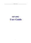
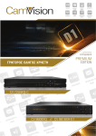
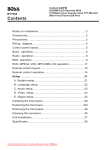
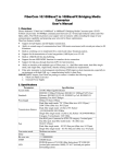
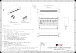
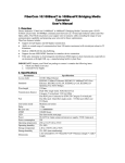
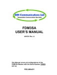
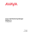
An Interactive Telelecture System with Hybrid ATM/IP
Networking
Jörg Liebeherr*
Steven R. Brown**
Rick Albertson***
* Department of Electrical Engineering
Polytechnic University
Brooklyn, NY 11201
Email: [email protected]
** Department of Computer Science
University of Virginia
Charlottesville, VA 22903
Email: [email protected]
*** Litton-FiberCom
Roanoke, Virginia 24012
Email: [email protected]
Abstract
Currently, there is much debate whether ATM (Asynchronous Transfer Mode) or IP (Internet Protocol) is the
better internetworking technology for multiparty multimedia applications. Proponents of ATM argue that
only a connection-oriented network can satisfy the stringent timeliness requirements of high-quality audio
and video data. Proponents of the Internet emphasize the scalability and flexibility of connectionless
networking. In this paper a multiparty multimedia telelecture system, called Distance Learning Controller
(DLC), is presented that uses both ATM and IP, thus, attempting to exploit the advantages of both
technologies, without suffering the drawbacks of either technology. The DLC system uses ATM for
transmission of broadcast-quality video and CD-quality audio, and IP-over-ATM for low-bandwidth
applications and conference control functions. This paper describes the hardware and software components
of the DLC system.
1
1
Introduction
Emerging integrated services networks that support the transmission of video, audio, and data in a
single physical network enable us to build distributed multimedia. A driving goal of many distributed
multimedia applications is the notion of telepresence, that is, the ability for people at different locations to
communicate as if they were present in the same room [Bell96].
We are concerned with distributed multimedia applications for education, so-called interactive
distance learning systems. Distance learning systems are currently in high demand as they may help
educational institutions provide increased educational opportunities in a cost-efficient manner. Traditionally,
interactive distance learning solutions are based on closed-circuit television systems over community access
television (CATV) and satellite networks. Instructional television over CATV (`cable’) networks is
inherently unidirectional and does not provide real-time feedback. Satellite networks permit bidirectional
transmissions, but incur high costs. All analog television systems, terrestrial or satellite, are limited to the
transmission of video and audio. Other media, e.g., text, cannot be transmitted in real-time. Integrated
services networks overcome the limitations of traditional instructional television systems and enable true
two-way learning.
Today, two internetworking technologies are candidates for providing the networking infrastructure
for distributed multimedia applications: Asynchronous Transfer Mode (ATM) and the Internet Protocol (IP).
Proponents of ATM argue that only a connection-oriented network can satisfy the stringent timeliness
requirements of high-quality audio and video data. Proponents of IP emphasize the robustness and scalability
properties of the connectionless transfer mode in IP.
In this paper we present an interactive distance learning system that employs both ATM and IP
networking. The system demonstrates that it is feasible to exploit the advantages of both ATM and IP
without experiencing their disadvantages. The system, called Distance Learning Controller (DLC), can
connect up to 32 participants in a telelecture. Using hardware video encoders the system delivers, at the
highest quality settings, broadcast-quality video and CD-quality audio. High-quality video and audio are
transmitted directly over ATM, while conference control and low-quality video and audio are transmitted
using IP-over-ATM. The DLC system described in this paper is currently being commercialized [DLC97].
The remainder of the paper is structured as follows. In Section 2 we review ATM and IP
technologies in the light of their ability to support multiparty multimedia applications. In Section 3 we
describe the hardware configuration of the DLC telelecture system, and in Section 4 we discuss the software
components of the DLC system. In Section 5 we discuss the steps involved in setting up and running a DLC
system. In Section 6 we describe how we use ATM signaling to enable dynamic dial-up telelectures. In
Section 7, we present the details of an IP-based control protocol that we developed for managing DLC
telelectures. In Section 8 we summarize our findings.
2
Networking Technologies for Interactive Multiparty Multimedia
Both ATM and IP are comprehensive internetworking technologies in the sense that it is feasible to
build interactive multiparty multimedia applications exclusively with ATM or exclusively with IP. In this
section we review the strengths and the weaknesses of ATM and IP networking, focusing on their ability to
support multiparty multimedia applications.
2
2.1
ATM Networking
ATM networks are connection-oriented packet switching networks. All data is transmitted over
virtual channels, henceforth referred to as connections, which must be established before any data transfer
can take place. For short-lived data flows, e.g., a single access to a web server, the time required to setup a
connection can exceed the time of the actual data transfer.
For multiparty multimedia applications, ATM provides multicast connections which build a
connection tree from a sender to multiple receivers. A drawback of multicast connections is that they are
unidirectional, i.e., from the sender to the receivers. Thus, in a multipoint-to-multipoint application with
more than one sender, ATM requires establishment of one multicast connection for each sender. The most
recent version of ATM (UNI1 Version 4.0 [UNI4.0]) specifies multipoint-to-multipoint connections,
however, currently available ATM equipment supports only point-to-multipoint connections.
ATM networks can offer a range of service guarantees for each individual connection [TM4.0]. The
guarantees given for a connection are called Quality-of-Service (QoS) and are specified in terms of
throughput, delays, and delay variations.
2.2
IP Networking
The Internet Protocol (IP) is the network protocol of the Internet. Data transmission in IP is
connectionless, which means that packets from the same end-to-end packet flow are treated independently
and can possibly take a different route through the network. A connectionless data transfer mode is
lightweight as no connection establishment is necessary.
IP has a powerful mechanism, called IP Multicast, for conducting multipoint-to-multipoint communications. The Multicast Backbone (MBONE) [CAS94] [MAC94] has offered an IP Multicast service on
the Internet for low-bandwidth video and audio conferences since 1992. Based on the recent ITU-T H.323
standard [ITU323], products for high-bandwidth video multipoint applications over IP Multicast are
emerging [OZE98]. Due to the limited throughput capacity of the Internet, high-bandwidth applications over
wide-area networks are currently not an option.
A drawback of IP is that it does not give QoS to individual end-to-end packet flows. Using the
signaling protocol RSVP [RFC2205] and new service models [RFC2210] it is possible to implement QoS in
IP networks, similar to ATM. However, at present, support for QoS in most IP networks is not available.
2.3
Mutally exclusive or Complementary?
Our discussion of ATM and IP shows that both technologies currently do not support the full
spectrum of network services needed for multiparty multimedia conferences. ATM is lacking a good solution
for connectionless short-lived packet flows and support for multipoint-to-multipoint connections. IP
networks, on the other hand, do not support data flows with strict quality-of-service requirements. While it is
true that both technologies will eventually overcome these drawbacks, application developers for high-end
multiparty multimedia applications are currently facing significant problems if they rely solely on ATM
networking or solely on IP networking.
1
UNI = User Network Interface.
3
Teacher
Student
Remote
Video
Remote
Video
ATM
Network
LightStream2020
ATM
Audio
Video
ATM
/LWWRQ
Video
/LWWRQ
CAMVision 7610
FiberCom
PC workstation
Audio
FiberCom
Codec
CAMVision 7610
Codec
PC workstation
Figure 1: Hardware Configuration of the DLC System.
In this paper we show that it is feasible to design high-end multiparty multimedia applications that
use both ATM and IP, thus, exploiting the advantages of both technologies without suffering the drawbacks
of either technology. Since it is relatively easy to run IP traffic over an ATM network [RFC1577]
[RFC1932], we can use IP and ATM seamlessly in the same application. In our DLC system, we transmit
high-bandwidth video and audio directly over ATM, and we transmit low-bandwidth control information (as
well as low-bandwidth video and audio) using IP-over-ATM.
3
Hardware Components
A Distance Learning Controller (DLC) setup connects up to 32 sites for an interactive telelecture;
One site is a “teacher site” and the other sites are “student sites”. Each site of a DLC telelecture must have
the following hardware available:
•
PC workstation,
•
Litton FiberCom CAMVision 7610 codec,
•
NTSC video camera and video monitor,
•
Connectivity to an ATM network.
In Figure 1 we depict the hardware setup for a conference with one teacher and one student site. At
the each site, a codec is connected to a PC workstation, a video camera, a TV monitor, and an ATM switch.
The CAMVision codec shown in Figure 2, encodes analog NTSC video to Motion JPEG (M-JPEG)
at full frame sizes and 30 fps2 video. The compressed video stream, with a data rate of 12 Mbps3 to 30 Mbps,
is transmitted directly over an ATM connection. At any time, only one video stream can be encoded or
decoded. In addition to video, the codec processes a stereo audio stream at CD-quality with 16-bit samples at
44.1 kHz.
2
fps = frames per second.
3
Mbps = Megabits per second.
4
Video Input/Output
Input Connections
Output Connections
Compression
Resolution
Latency
Audio
Input
Output
Connections
Management Protocol
Physical Dimensions
ATM Ports
2 NTSC, 1 S-Video
1 NTSC, 1 S-Video
JPEG
(Q-Factor programmable,
12 Mbps to 30 Mbps)
Full duplex, 30 frames/sec,
640x480 pixels/frame
< 10ms
1 stereo channel, 44.1 KHz
1 stereo channel, 44.1 KHz
RCA
SNMP
3.0"H x 16.5"W x 16.5"D
7610-02: OC-3 (to switch)
and OC-3 (to workstation)
Figure 2. Fibercom CAMVision 7610 Codec.
The PC workstation is running Windows NT 4.0. The PC has an OC-3 fiber optic ATM card that
connects to one of two ports on the codec. (The other port on the codec connects to an ATM switch.) There
are two reasons for connecting the workstation to the codec, as opposed to connecting the workstation
directly to an ATM switch. First, we can use the workstation to send control commands to the codec for
setting up and adjusting codec parameters. Second, with the chosen configuration, the PC workstation can
perform dynamic setup of ATM connections on behalf of the code using ATM UNI signaling.
The ATM network is any private or public ATM network that supports the ATM UNI 3.1 [UNI3.1]
interface as specified by the ATM Forum.
4
DLC Software Components
The DLC software is built on top of the existing software infrastructure for networking and video
encoding standards. In Figure 3 we show the software components that are used in the DLC.
•
ATM and UNI 3.1 Signaling – ATM multicast connections perform the end-to-end data transfer in our
system. For each site of the DLC session we require two ATM multicast connections: one for hardwareencoded video and one for hardware-encoded audio. In addition we require one ATM unicast connection
to each participant for IP-over-ATM traffic. Note that having one unicast connection to each participant
involves considerable overhead. Using LAN Emulation (LANE) [LANE95] and Multiprotocol-over-ATM
(MPOA) [MPOA96] services, the number of ATM connections necessary for IP-over-ATM traffic could
be reduced to a single connection. However, both LANE and MPOA are not available in many existing
ATM networks.
There are two types of ATM connections: Permanent Virtual Connections (PVCs) and Switched Virtual
Connections (SVCs). PVCs are established manually by a network operator and cannot be controlled by
a user software application. SVCs are maintained by user software through the signaling features of
ATM. The DLC system can be run over both PVCs and SVCs. For SVCs, we have implemented a dial-
5
up module where signaling is performed using the WinSock2 API4 [WINAPI][WINSPI] for ATM UNI
3.1 signaling. The steps for setting up the SVCs for a telelecture session are discussed in Section 6.
SNMP
(Device Control)
Audio
Video
Internet ATM
Audio Audio
Internet ATM
Video Video
IP Multicast
Conference
Control
ATM Multicast
IP
ATM
Figure 3: Architecture of Software Components for DLC System.
•
IP and IP Multicast – IP packets are transmitted over ATM using the Classical IP over ATM model
[RFC1577]. In the current implementation, all sites are connected by a full mesh of multicast PVCs or
multicast SVCs. The ATM Virtual Channel Identifier (VCI) for an IP address is dynamically assigned
when we use SVCs, and preassigned if we use PVCs.
A problem when transmitting IP Multicast traffic over an ATM network is the lack of a standard for
transmission of IP Multicast traffic over an ATM network. For this reason, the NT version of the DLC,
which is presented in this paper, does not use IP Multicast, and emulates IP Multicast with several UDP
unicast streams.5
•
ATM Video and Audio – We refer to ATM video and ATM audio as the encoded video and audio
streams that are generated by codec. The video encoding format is the de-facto standard Motion JPEG
(MJPEG). It is important to note that MJPEG is not an international standard, and MJPEG equipment
from different vendors is typically not interoperable. On the other hand, as compared to MPEG-1 or
MPEG-2, MJPEG has the advantage of incurring significantly lower encoding delays.
•
IP audio and video – In addition to the high-quality ATM video and ATM audio, the DLC system also
includes low-bandwidth video and audio transmissions. Low-quality video and audio is transmitted over
IP and referred to as IP video and IP audio. We use the tools vat and vic from Lawrence Berkeley Labs
[KUM95] for IP audio and video. Both tools perform encoding and decoding completely in software.
Thus, by supporting IP video and audio applications, a DLC session can include sites that do not have a
4
API = Application Programming Interface.
5
Our Solaris version of the system, running on SUN Sparc workstations, can take advantage of IP Multicast.
6
hardware codec. Video encoding in vic uses the H.261 encoding standard with a typical data rate of 128
kbps6. The vat audio tool supports a variety of encoding formats at bit rates ranging from 8-64 kbps.
•
SNMP – The parameters of the codec are set using the Simple Network Management Protocol (SNMP)
[RFC1157]. The workstation controls the parameters of the local codec by sending SNMP commands. In
our DLC system, we use SNMP to control the following parameters of the codec:
•
•
ATM connection identifiers of all participants for both audio and video,
•
ATM connection identifiers of the “active” video stream, where the active video stream is the one
that is currently being encoded or decoded.
•
Video compression factor which determines the quality and the bandwidth requirement of the video
stream.
Conference Control – There are two mechanisms for conference control in the DLC system: (1) ATM
connection setup, and (2) orchestration of the videoteleconferencing session. The setup of ATM
connections is done prior to running a DLC telelecture. Following the connection setup, orchestration of
the DLC telelecture is handled by an IP-based conference control protocol, which executes functions for
joining a conference, leaving a conference, and transmission of conference parameters. The conference
control protocol is described in detail in Section 7.
5
Operation of a DLC Telelecture
There are a series of steps involved in establishing and maintaining a Distance Learning Controller
telelecture session (“DLC session”). Before a DLC session can start, point-to-point and point-to-multipoint
ATM connections must be established between all sites. Following the establishment of ATM connections, a
DLC teacher application (“teacher”) can create a DLC session, which can then be joined by DLC student
applications (”students”). During a DLC session, the teacher is responsible for controlling the parameters of
the telelecture.
5.1
Establishing a DLC Sessions
In Figure 4, we show the steps involved in starting a DLC session. First, the teacher uses an interface
(`conference wizard’) to create a telelecture (Step 1). When a student joins into a conference (Step 2), the
teacher sees the student as an icon in the teacher interface. After successful joining, teacher and student
exchange ATM video and audio using the codec (Step 4).
After a DLC session has been established, the teacher controls the interactions in the conference. At
any given point in time during the course of a DLC session, only one participant can be the transmitter of
ATM video. All participants in the DLC session see the ATM video. The teacher is the only participant with
the capability to determine which participant is transmitting video.
6
kbps = Kilobits per second.
7
Teacher
Student
time
1
2
3
3
Figure 4: Architecture of Software Components for DLC System.
Codec controls
Internet video control
Internet audio control
Students are represented
as icons
Raised hand indicates a
student question
Figure 5: Graphical User Interface for DLC Teacher.
8
CAMVision controls
List of active session
participants
Internet video/audio
Question button
Figure 6: Graphical User Interface for DLC Student.
5.2
Session Control
After a DLC session is established, teacher and students have available a set of control functions.
The following functions are supported in a DLC session:
•
A student indicates to the teacher a question (“student raises hand”).
•
The teacher selects a student for transmitting ATM video.
•
A student leaves the conference.
•
The teacher drops a student from the DLC session.
Teacher and student have different graphical user interfaces (GUIs), shown in Figure 5 and 6 for
teacher and student, respectively.
The teacher GUI depicted in Figure 5 has one icon for each student who has joined the conference. In the
figure, we see that six students have joined the conference. By double clicking on a student icon, the teacher
selects this student to be the transmitter of ATM video. The right border of the teacher GUI in Figure 5
depicts a set of buttons. By pushing the button labeled `Codec controls’, the teacher invokes a control panel
for setting the compression ratio of the codec. The buttons labeled `Internet video control’ and `Internet
audio control’ start transmission of Internet video (vic) and audio (vat), respectively.
The student GUI, shown in Figure 6, is similar to the teacher GUI. The interface has a list of the names
of all lecture participants. The icons for code control, Internet video control, and Internet audio control serve
the same functions as for the teacher. The question button is used by a student to send a notification to the
teacher. If the button is pushed, a raised hand appears in the user interface of the teacher, next to the icon of
the student who pushed the button. For example, one of the icons in Figure 5 depicts a student (“Karen”)
who has pushed the question button.
A student leaves a conference by selecting the quit option in the conference menu of its interface. In
addition, the teacher has the option of dropping a student from the conference at any time. The entire
conference is terminated as soon as the teacher quits its DLC interface.
Untethered Operation: The tasks of the teacher in a DLC session are demanding, as the teacher must
simultaneously give a lecture and control the parameters of the conference. We simplify the complexity of
the teacher’s role in two ways, as illustrated in Figure 7. First, we overlay the workstation and the video
output on a single television monitor. As a result, the teacher only needs to observe a single display. Second,
9
the teacher is given an infrared mouse with a set of pre-programmed functions. With the remote mouse, the
teacher can control the user interface shown in Figure 5. Using the pre-programmed functions, the teacher
can switch the transmitter of ATM video simply by pushing a button.
In Figure 4 (lower left corner) we show a snapshot that depicts the overlay of user interface and codec video.
Teacher’s
Workstation
Wireless
mouse
controls
user
interface
Video from
Codec
Overlay of video
and user interface
Teacher
Teacher uses
wireless mouse
Video Monitor
of Teacher
Figure 7: Untethered Control of User Interface by Teacher.
6
Dial-Up of DLC Sessions
The system as described in Section 5 assumes that ATM connections are established before a DLC
session is started. We have added a dial-up component to the DLC system that performs the setup of ATM
connections using ATM UNI 3.1 signaling [UNI3.1]. The dial-up component achieves dynamic
establishment of point-to-point and point-to-multipoint ATM connections between all sites that want to
participate in a DLC session. In the DLC software we use the Winsock 2 application programming interface
for UNI signaling [WINAPI][WINSPI].
The user interactions for the dynamic setup of a DLC session are illustrated in Figure 8. The dialup
procedure starts by reading the ATM and IP addresses of potential participants from an address file. A dialup program, called the PatchPanel, uses these addresses to establish SVCs (Step 1 in Figure 8). The
PatchPanel displays the status of the dial-up procedure. Also, the PatchPanel generates a configuration file
(Step 2 in Figure 8) that is read by the DLC teacher application to create a DLC session (Step 3 in Figure 8).
10
1
PatchPanel reads
ATM addresses and
establishes
connections
2
PatchPanel writes
configuration file
3
PatchPanel starts DLC
which reads configuration
file
Figure 8: Dial-Up of a DLC Session.
7
DLC Conference Management and Control
The core of the DLC system presented in Section 5 is a protocol that performs conference control
functions. Conference control is concerned with determining the parameters of an ongoing conference. The
main functions of conference control are membership management and floor control management.
Membership management is concerned with enforcing policies for joining and leaving a conference. Floor
control management refers to the mechanism for granting mutually exclusive access to non-shared resources.
In the following we describe the components of the conference control protocol.
7.1
State-of-the-Art
In recent years, many conference control protocols have been proposed for teleconferencing on the
Multicast Backbone (MBONE) of the Internet [CAS94] [MAC94]. By itself, MBONE teleconferences are
‘loosely controlled’ in that participants share little or no state information. However, many applications,
11
including the telelecture application described in this paper, require a tighter control of the conference
members. The Multiparty Multimedia Session Control (MMUSIC) working group in the IETF has presented
several draft proposals for negotiation of conference membership, media configuration, and support for user
initiation of multimedia multiparty session [BOR96][HAN96][HAN97][HAN97b]. Influential on the recent
work in the MMUSIC working group has been the ITU-T T.120 [ITU120] protocol standard for multiparty
multimedia conferences. Currently, several conference management systems are available, including, sdr
[HAN97a], mmcc [SCHO93], confman [FRIC95], and gwtts [LIEB95]. Protocols that support conference
management functions include the Simple Conference Invitation Protocol (SCIP) [SCHU96] and the Session
Invitation Protocol (SIP) [HAN97b], which help to locate and invite participants, the Session Announcement
Protocol (SAP) [HAN96] which conveys session information, and the Simple Conference Control Protocol
(SCCP) [BOR96], which performs membership and floor control management.
Most existing conference control and management protocols are designed for symmetric conference
sessions, i.e., conference sessions between peers. Indeed, much effort in these protocols is expended to
ensure that all participants are treated fairly, without one participant dominating the conference. In contrast,
the relationship between participants in our DLC system is asymmetric, since the teacher has complete
control over the conference. By exploiting the fact that the teacher plays a dominant role in controlling a
telelecture, we can considerably reduce the overhead of the control protocol.
7.2
The DLC Conference Control Protocol
The conference control protocol is implemented for the Windows NT platform in Visual C++ 5.0. The
protocol was originally designed for a multicast IP network. However, since IP multicast over ATM
solutions [RFC2149] have not emerged for the Windows NT platform, we have emulated IP Multicasting by
UDP unicast messages as follows. If the teacher sends a message to all students, it transmits the same
message to all students. In our protocol, each student only communicates with the teacher. Students do not
send control messages to one another. This centralized solution which has a single point of failure at the
teacher is acceptable, since the semantics of a DLC session requires the teacher to be present at all times.
Note that UDP provides only an unreliable connectionless service without a recovery of lost packets. An
advantage of an unreliable service is that it allows us to design the control protocol as a soft-state protocol
[RFC1102], which has a very low degree of complexity. In a soft-state control protocol, state information is
not considered permanent, and all state information must be periodically refreshed. A soft-state conference
control protocol requires all conference members to refresh their state information, or, otherwise, they are
deleted from the conference. A major advantage of a soft-state protocol is that it gracefully recovers from
failures. If a conference participant fails, the state information on this participant will eventually be deleted,
and no recovery action must be taken. A drawback of the soft-state protocol is that packet losses are not
recovered until the next time the state is refreshed.
The state of each conference member, teacher or student, is represented by a tuple. The tuple for student
and teacher are similar, but not identical. The most important attributes of the state tuple of a student and
teacher are summarized in Table 2.
12
IPAddress
TTL
Type
Unsigned
integer
Unsigned
integer
Unsigned
Integer
Student
Id
Semantics
Teacher
Attribute
Conference-wide unique identifier for the
student
IP address of local host
✓
✓
✓
✓
✓
✓
–
✓
HandUp
Boolean
Time-to-Live; indicates a time limit that
the teacher (student) will wait for a state
update from the student (teacher)
True if question button is pressed
Control
Boolean
True if this site has floor control
✓
✓
Identifies network application (ATM
Codec, Internet video)
True if the teacher has started this
application
True if the appellation is running at this
site.
Application specific parameters (e.g.,
compression parameters for codec)
✓
✓
✓
✓
–
✓
✓
✓
For Each Network Application:
NetworkAppType
IsActivated
Unsigned
integer
Boolean
IsRunning
Boolean
Application
Parameters
Application
dependent
Table 1: State Tuples for Teacher and Students
(A check (➼) indicates that an attribute is present at teacher and/or student).
Each network student of the conference is responsible for periodically transmitting its state information
to the teacher. If the teacher has not received a message from a student for a period of time specified by the
teacher’s TTL attribute, the teacher will assume that the student has left the conference. The teacher, in turn,
periodically transmits information on the entire conference to all students.
In our conference control protocol, the teacher and student exchange control packets whenever the state
of the conference changes, or when the conference state information must be refreshed. The different packet
formats used in our protocol are summarized in Table 4. Each row in the table indicates a different packet
format.
(a) Joining the Conference
•
JOIN – A student who wants to join the conference sends a JOIN packet to the teacher. The JOIN packet
contains the Internet address of the student.
•
ACCEPT – If the teacher decides to let a student join, it sends an ACCEPT packet to the student in
response to the JOIN packet. The ACCEPT packet acknowledges that the student has been added to the list
of participants, and contains the complete conference state information.
•
UPDATE – After accepting a student via an ACCEPT packet, the teacher sends an UPDATE packet to all
students already joined in the conference. The UPDATE packet contains the state tuple of the new student.
13
(b) Maintaining State Information
•
PING – Every PING_TIMEOUT (= 4,000) milliseconds, a student sends a PING packet to the teacher. The
PING packet informs the teacher that the student is still active, and contains the current state of the
student. If the teacher does not receive a PING packet from a student, it will eventually drop this student
from the conference. Initially, the teacher sets the Time-To-Live (TTL) field of a student to PING_GRACE
(= 5) timeout intervals. After each PING_TIMEOUT milliseconds, the TTL value is decremented. When
the teacher receives a PING packet, the TTL value is reinitialized. If the TTL reaches zero, the student is
dropped. So, it takes PING_TIMEOUT × PING_GRACE (= 40) seconds before a defunct student is dropped.
•
STATE – Every PING_TIMEOUT seconds, the teacher sends a STATE packet to each student. The packet
contains the state information on the conference. The information in the STATE packet is aging in a
similar fashion as the PING packet. If a student does not receive a STATE packet after PING_TIMEOUT
seconds, the TTL value of the state is decremented. If TTL reaches zero, the student assumes that the
teacher has abnormally terminated, and assumes that the conference has ended.
•
UPDATE – Whenever the state change of a single student is very relevant to other students, the student
sends an UPDATE packet to the teacher. The teacher, in turn, forwards the same UPDATE packet to all
students. The UPDATE packet contains the change in the conference state. Note that the UPDATE packet
is an optimization in that it contains a subset of the contents of a PING or STATE packet. Without an
UPDATE packet, the state change will not be communicated until the next PING or STATE packet.
(c) Leaving a Conference
•
QUIT – When a student leaves the conference it sends a QUIT packet to the teacher. After receiving a
QUIT packet, the teacher sends no further packets to this student. If the student who has sent a QUIT
packet is holding floor control for a shared resource, the floor control goes back to the teacher. After
receiving a QUIT packet, the teacher sends an UPDATE packet to all students still in the conference.
•
DROP – A teacher can force a student to leave the conference by sending a DROP packet. Upon
receiving the packet, the student closes all applications and does not send further packets to the teacher.
The teacher will perform the same actions that are taken when receiving a QUIT packet from the
students, i.e., take back floor control and send an UPDATE packet to all students.
(d) Managing Applications
The teacher is responsible for starting and terminating shared network applications such as video
transmission, audio transmission, shared web browsers, etc. The number of network applications supported
by the telelecture is not limited in the presented protocol. Note, however, that adding or removing network
applications requires modification of the user interfaces described in Figures 5 and 6. Currently, the network
applications listed in Table 3 have been included in different versions of the telelecture system. The DLC
system described in Section 5 only includes a subset of these network applications.
14
Application
Execute
Available in
DLC System
ATM Video, ATM Audio
Hardware codec
✓
Internet Video
vic
✓
Internet Audio
vat
✓
Shared Web browser
Netscape
–
Shared Whiteboard
LBL Whiteboard
–
[KUM95]
Table 3: Network Applications.
•
STARTAPP – When starting a new application, the teacher sends a STARTAPP to each student. The
STARTAPP packet contains the parameters necessary to run the application. After receiving a STARTAPP
packet, the student sets the ISACTIVATED state parameter for this application. When the student starts the
application, the ISRUNNING flag for this application is set. For most applications it makes sense, to start
the application at a student (and set ISRUNNING) when a STARTAPP packet is received (and
ISACTIVATED is set). In this case, by resetting ISRUNNING, a student can disable an application. For
example, in the DLC system, an application that is activated by a STARTAPP packet is automatically
started at the student.
•
KILLAPP – The KILLAPP is sent by a teacher to students to terminate a network application. The packet
is sent to all students. Upon receiving a KILLAPP packet, a student sets the ISACTIVATED and
ISRUNNING parameters for this resource to FALSE.
•
CONTROL – In our protocol there is only one floor for the entire conference. A student who has the
floor is in control of all applications that have a non-sharable resource. Examples of non-sharable
resources are the transmission of video when using the ATM codecs or control of a shared-web browser
application. In principle, it is possible to have separate floor control for each application that has a nonsharable resource. However, since the number of applications that require floor control is typically small,
we maintain only a single floor for the entire conference. Floor control is only passed between teacher
and students. A teacher passes a floor control to a student with identifier ID by sending a
CONTROL(GRANT, ID) packet. The teacher takes control back by sending a CONTROL(TAKE) packet.
In order to pass floor control from one student to another, the teacher first takes control and then passes
control to the student. This scheme is conservative, but ensures that packet losses do not cause
inconsistent state for the floor control. Whenever floor control moves to a new site, the teacher sends an
UPDATE packet to all students in the conference.
•
HANDUP, HANDDOWN – A HANDUP packet is a notification signal sent from the student to the
teacher. The teacher acknowledges the signal by sending a HANDDOWN packet. In the DLC system, the
HANDUP packet is used for raising hands in the teacher interface as shown in Figure 5.
15
Type
Parameters
Semantics
Join
NAME,
STUDENTIPADDR
Student wants to join the session
Ping
<ID, STATE(ID)>
HandUp
ID
Update
<ID, STATE(ID)>
This packet contains the current state
information on the student
Student indicates a signal to the
teacher
Student updates its state information
Quit
ID
Student leaves session
Student → Teacher
Teacher → Student
State
<ID1, STATE(ID1)>, Complete state information of the
conference
…,
<IDN,STATE(IDN)>,
<STATE(TEACHER)>
Accept
<ID,STATE(ID)>,
<ID1, STATE(ID1)>,
…,
<IDN,STATE(IDN)>,
<STATE(TEACHER)>
Accepts new student. Contains identifier for new student and complete
state information on the conference
Update
<ID, STATE(ID)>
Drop
ID
HandDown
ID
{GRANT, TAKE}, ID
Acknowledges a HANDUP packet
StartApp
NETWORKAPPTYPE,
PARAMETERS
Starts a network application with
provided application-specific parameters
KillApp
NETWORKAPPTYPE
Terminates a network application
Control
Contains state information of a
single student
Drops a student from the conference
Grant floor control to a student or
take floor control from a student
Table 4: Packet Formats.
16
8
Summary
The DLC system described in this paper has been implemented and is currently commercialized by
Litton Fibercom, the producer of the hardware codec.
1. The integration of ATM and IP networking in the DLC system is performing well. Consider, for a
moment, the most complex operation in the DLC system is the switching of ATM video transmission
from the teacher to a student. To perform the switch, (1) the teacher workstation sends an SNMP
command to the local codec to stop transmitting and begin receiving video, (2) the teacher sends a
CONTROL packet to all students. When receiving the packet, (3) the student who is the new transmitter of
ATM video sends an SNMP command to its local codec to start transmission of video, and (4) all other
students send an SNMP command to their local codec to switch the ATM connection where they receive
their ATM video.
In our development environment, switching the video transmission appeared instantaneous, similar to
switching a TV channel with a remote control (The comparison is valid since the teacher has an infrared
remote control to switch the video transmissions (see Figure 7)).
2. Having the PC perform signaling on behalf of the codec and communicate the results of the signaling via
SNMP, showed that we can bridge the gap between different generations of ATM.
3. The biggest limitations of the DLC system is due to the lack of a standard for sending IP Multicast traffic
over an ATM network. Solutions such as Multicast Address Resolution Server (MARS) [RFC2149] are
urgently needed to enable efficient IP multipoint communication over ATM. Note that there are
alternative to send IP traffic over an ATM network, such as LAN Emulation (LANE) [LANE95] and
Multiprotocol-over-ATM (MPOA) [MPOA96]. However, LANE and MPOA services are not provided
in many ATM networks.
4. Another bottleneck in the DLC system design is the mesh of ATM multicast connections. Recall that we
require three ATM multicast connections for each participant of the ATM conference (video, audio, and
IP traffic). Since the UNI 4.0 version of ATM specifies multipoint-to-multipoint ATM connections, this
bottleneck will disappear once UNI 4.0 capable products become available.
5. The future development of high-end videoconferencing solutions will depend on the success of current
standardization efforts and the adoption of these standards by video and network equipment vendors. For
video transmissions, the ITU-T H.323 series of recommendations has specified the transmission of highquality MPEG-2 video over packet-switching networks. By exploiting H.310, it will become feasible to
build an all-IP version of the DLC system with interoperable codecs from different vendors.
9
Acknowledgements
We gratefully acknowledge the support of Virginia’s Center for Innovative Technology for partially
supporting this project. Kira Attwood and Andy Booker implemented the gwTTs system, the predecessor of
the presented conference control protocol. The presented user interface of the DLC is based on Chris Rude’s
adaptation of gwTTs to Windows NT.
17
10 References
[CAS94]
S. Casner, “Are you on the MBONE?”, IEEE Multimedia, Vol. 1, No. 2, Summer 1994.
[DLC97]
Litton FiberCom, “CAMVision 7610 Distance Learning Controller”, http://www.fibercom.com/dlc.htm, December 1997.
[BEL96]
G. Bell and J. Gemmell, “On-ramp Prospects for the Information Superhighway Dream",
Communications of the ACM, Vol. 39, No. 7, pp. 55-61, July 1996.
[BOR96]
C. Bormann, J. Ott, and C. Reichert, “Simple Conference Control Protocol”, Internet Draft,
IETF, draft-ietf-mmusic-sccp-00.txt, June 1996.
[FRIC95]
C. Fricke, “Confman Version 1.1 User Manual”, (in German), University of Hannover,
Germany, 1995.
[HAN96]
M. Handley, “Session Announcement Protocol”, Presentation, IETF Meeting Minutes,
MMUSIC Working Group, June 1996.
[HAN97]
M. Handley, J. Crowcroft, C. Bormann, and J. Ott, “The Internet Multimedia Conferencing
Architecture”, Internet Draft, IETF, draft-ietf-mmusic-confarch-00.ps, July 1997.
[HAN97a] M. Handley and V. Jacobson, “Session Description Protocol”, Internet Draft, IETF, draft-ietfmmusic-sdp-06.ps, January 1997.
[HAN97b] M. Handley, E. Schooler, and H. Schulzrinne, “Session Invitation Protocol”, Internet Draft,
IETF, draft-ietf-mmusic-sip-04.txt, November 1997.
[ITU120]
ITU-T Study Group 8, “T.120 - Transmission Protocols For Multimedia Data”,
Recommendation, July 1996.
[ITU124]
ITU-T Study Group 8, “T.124 Generic Conference Control”, Recommendation, August 1995.
[ITU323]
ITU-T Study Group 16, “H.323 Visual telephone systems and equipment for local area
networks which provide a non-guaranteed quality of service”, Recommendation, November
1996.
[KUM95]
V. Kumar, "MBone: Interactive Multimedia On The Internet", Macmillan Publishing,
November 1995.
[LANE95] ATM Forum ,“LAN Emulation over ATM 1.0”, Specification af-lane-0021.000, January 1995.
[LIEB95]
J. Liebeherr, “gwTTS - The grounds-wide Tele-Tutoring System”, http://www.cs.
virginia.edu/~gwtts, University of Virginia, 1995.
[MAC94]
M. Macedonia and D. Brutzman. “MBONE Provides Audio and Video Across the Internet”,
IEEE Computer, pp 30-36. April 1994.
[MPOA96] ATM Forum, “Multi-Protocol over ATM, Version 1.0”, Specification af-mpoa-0087.000, July
1997.
[OZE98]
J. Ozer, “Selecting the Right Streaming Video Product for Your Application”, Desktop Video
Communications, Vol. 3, No. 1, pp. 14 – 19, January/February 1998.
[PAR93]
C. Partridge, Gigabit Networking, Addison-Wesley, 1993.
[RFC1102] D. Clark, “Policy Routing in Internet Protocols”, Request for Comments, IETF, RFC 1102, May
1989.
[RFC1157] J. D. Case, M. S. Fedor, M. L. Schoffstall, and C. Davin, “Simple Network Management
(SNMP)”, Request for Comments, IETF, RFC 1157, May 1990.
18
[RFC1577] M. Laubach, “Classical IP and ARP over ATM”, Request for Comments, IETF, RFC 1577,
January 1994.
[RFC1932] R. Cole, D. Shur, and C. Villamizar, ``IP over ATM: A Framework Document'', Request for
Comments, IETF, RFC 1932, April 1996.
[RFC2149] R. Talpade and M. H. Ammar, “Multicast Server Architectures for MARS-based Multicasting”,
Request for Comments, IETF, RFC 2149, May 1997.
[RFC2205] R. Braden, L. Zhang, S. Berson, S. Herzog, S. Jamin, “Resource ReSerVation Protocol (RSVP),
Version 1, Functional Specification”, Internet Engineering Task Force, RFC 2205, September
1997.
[RFC2210] J. Wroclawski, “The Use of RSVP with IETF Integrated Services”, Request for Comments,
IETF, RFC 2210, September 1997.
[SCHO93] E. M. Schooler, “Case Study: Multimedia Conference Control in a Packet-switched
Teleconferencing System”, Journal of Internetworking: Research and Experience, Vol. 4, No.
2, pp. 99-120, June 1993.
[SCHO92] E. M. Schooler and S.L., Casner, “An Architecture for Multimedia Connection Management”,
ACM Computer Communication Review, Vol.22, No.3, July 1992.
[SCHU96] H. Schulzrinne, “Simple Conference Invitation Protocol”, Internet Draft, IETF, draft-ietfmmusic-scip-00.txt, February 1996.
[SCHU96a] H. Schulzrinne, et.al., “RTP: A Transport Protocol for Real-Time Applications”, Request for
Comments, IETF, RFC 1889, February 1996.
[SECH86]
S. Sechrest, “Networking Implementation Notes - 4.3BSD Edition”, Department of Computer
Science, University of California, Berkeley, 1986.
[STEV94]
W.R. Stevens, TCP/IP Illustrated, Vol. I, Addison Wesley, 1994.
[TM4.0]
N. Giroux (chair), “ATM Traffic Management 4.0”, ATM Forum, Specification af-tm0056.000, April 1996.
[UNI3.1]
G. Dobrowski (chair), “ATM User-Network Interface Specification. Version 3.1”, ATM
Forum, Specification af-uni-0010.002, 1994.
[UNI4.0]
P. Samudra (editor), “UNI Signaling 4.0”, ATM Forum, Specification af-sig-0061.000, July
1996.
[WAL96]
J. Walrand and P. Varaiya, “High-Performance Communication Networks”, Morgan
Kaufmann, 1996.
[WINAPI] “Windows Sockets 2 Application Programming Interface An Interface for Trans-parent
Network Programming Under Microsoft Windows”, Revision 2.2.0, May 1996.
[WINSPI]
“Windows Sockets 2 Service Provider Interface A Service Provider Interface for Transparent
Network Programming under Microsoft Windows”, Revision 2.2.0, May 1996.
19