1
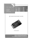
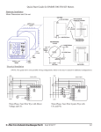
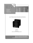
FiberCom 10/100BaseT to 100BaseFX Bridging Media
Converter
User’s Manual
1. Overview
Electro Industries’ FiberCom 10/100BaseT to 100BaseFX Bridging Media Converter (part # EI-FP8110SA-25) provides 10/100Mbps communication between Cat 5 twisted pair Ethernet cables and Fiber
Optic cables. The FiberCom protects your copper-wire investment, while extending the range of your
communication capability and preparing your network for future optimization.
FiberCom features include:
• Support for half-duplex and full-duplex transmission.
• Ability to extend range of communication from 1000 meters maximum (with twisted pair alone) to 80
kilometers.
• Built-in switching core to implement flow control and reduce broadcast packets.
• Support for the transmission of extra long packets (1600 bytes) over VLAN.
• Built-in 128kB RAM for data buffering.
• Support for auto MDI-MDIX function for seamless device connection.
• Support for link pass-through function (LPF) for fault detection.
• Ability to interface with multiple types of Fiber ports, i.e., dual-fiber multi-mode, dual-fiber singlemode, and single-fiber, single-mode, thereby meeting extended user requirements.
• Fiber optic immunity to electromagnetic interference (EMI) improves data transmission, especially in
environments with high EMI, e.g., a manufacturing facility’s plant floor.
IMPORTANT! Inspect your FiberCom package to ensure it contains the following items:
1. FiberCom Media Converter
2. External Power Supply
2. Specifications
Parameters
Access mode
Standards
Wavelength
Transmission distance
Port
Conversion mode
Delay
Bit error rate
MTBF
LED
Specifications
10/100 Mbps Gigabit Ethernet
IEEE802.3 10BaseT Ethernet, IEEE802.3U 100BaseTX/FX Fast
Ethernet, IEEE802.1Q VLAN, IEEE802.1p CoS, IEEE802.1D
Spanning Tree MAC Bridges
850nm/1310nm/1550nm
Dual-fiber multi-mode: 721’/220m (fiber size: 62.5/125µm) /
1804’/550m (fiber size: 50/125µm)
Dual-fiber single-mode: (32.8k to 393.7k)feet/
(10/20/40/60/80/100/120)Km
Single-fiber single-mode: (32.8k to 262.5k)feet/ 10/20/40/60/80Km
Category-5 twisted pairs: 328’/100m
One RJ45 port: Connected to STP/UTP category-5 twisted pairs
One fiber port: dual-fiber multi-mode – SC (fiber size:
50,62.5/125µm)
Dual-fiber single-mode – SC/FC fiber port (fiber size: 9/125µm)
Single-fiber single-mode – SC/FC fiber port (fiber size: 9/125µm)
Medium conversion
<10µs
<1/1000000000
100,000 hours
POWER (power), FX LINK (fiber link action), TP LINK100
(twisted pair connection 100M), TP ACT (twisted pair packet
forwarding action)
Power
Power consumption
Operating temperature
Operating humidity
Storage temperature
Storage humidity
Dimensions
90-265VAC Input using external power supply/ 5VDC Input jack
5W
(50 to 131)°F/(10 to 55)°C
5%~90%
(-40 to 158)°F/(-40 to 70)°C
5%~90% (non-condensing)
1.02”/26mm(H)*2.75”/70mm(W)*3.69”/94mm(L) (height * width *
length)
3. Connection
Connect the FiberCom Media Converter as follows:
a. Connect the network device (work station, hub or switch) with
RJ45 interface to the RJ45 jack of the FiberCom through
twisted-pair.
b. Connect the multi/single mode fiber to the SC/ST Fiber
interface of the FiberCom.
Fiber
c. Plug the supplied Power supply into the FiberCom.
Jack
d. Once the devices are powered on, the FiberCom LEDs
indicate connection status. See next section.
RJ45
Jack
4. Front Panel Indicators
Number
1
2
3
4
LED
DUP
Power supply
Input jack
Function
UTP port duplex LED
Status
Meaning
ON Full-duplex
OFF Half-duplex
FPFiber port link/action status
ON Fiber link is ACTIVE
LINK
LED
OFF Fiber link is INACTIVE
PWR
Power LED
ON Power is ON
OFF Power is OFF
RX UTP port link/action status LED ON Data is being received
Blink Data has been transmitted (not currently transmitting)
5
100
6
TX
OFF
ON
OFF
UTP port link/action status LED ON
Blink
OFF
UTP port speed LED
Data is not being sent out
100M speed
10M speed
Fiber link is OK
Data is being received or transmitted
Fiber link has failed
5. Troubleshooting
If the FiberCom Media Converter fails to operate, follow these steps:
No:
1. Is the FiberCom’s Power LED
- Is the power supply compatible with the AC
illuminated? (See page 10)
outlet?
- Is the power supply installed properly in the
FiberCom and the AC outlet?
- Contact EIG’s technical support.
Yes: continue to step 2.
2. Is the “Duplex/Link”LED
No: check the copper cables to insure proper connection.
illuminated on a port with
Yes:
twisted-pair cable installed?
- Amber light means the FiberCom has
selected half-duplex mode.
- Green light means the FiberCom has
selected full-duplex mode.
If the mode is not correct, disconnect and reconnect
the twisted pair cable to restart the initialization
process.
Continue to step 3.
3. Is the “LACT” LED
No:
illuminated on the on the fiber
- Check the fiber cables for proper
cable port?
connection.
- Verify that the TX and RX cables are
connected to the FiberCom’s RX and TX
ports, respectively.
Yes: continue to step 4.
4. Is the “Speed” LED
No: check the copper cables for proper connection.
illuminated on a port with
Yes:
twisted-pair cable installed?
- Amber light means the FiberCom has
selected 10Mbps operation.
- Green light means the FiberCom has
selected 100Mbps operation.
If the speed is not correct, disconnect and reconnect
the twisted pair cable to restart the initialization
process.
FCC RFI Statement
Federal Communications Commission (FCC) Radio Frequency
Interference
This device complies with part 15 of FCC regulations.
E Electro Industries/GaugeTech
“The Leader in Power Monitoring and Control”
1800 Shames Drive
Westbury, NY 11590
(Tel) 516-334-0870
(FAX) 516-338-4741
www.electroind.com
Doc# E201701 V.1.01
May 10, 2010