1
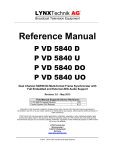
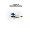
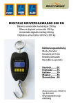
SBot v2.0 – Educational Robot for Clubs and Classrooms
Introduction
SBot is a simple robotic system for people who would like to learn or perform microcontroller programming for
robotics applications. It is suitable for the beginners for simple applications as well as for advanced users as a
platform for experiments in Artificial Intelligence. The robot is communicating with the computer or another master
device over the BlueTooth radio serial communication link. A good quality base with multiple mounting holes
allows easy extendability with additional components, and the universal PCB is ready for extending the robot with
custom electronics.
Specifications Overview
Robot diameter including
the bumper
Robot dimensions without
bumper
Power supply
Weight (without batteries)
Weight (with batteries)
Propulsion
Speed
MCU
Programming interfaces
BlueTooth range with
direct visibility
I/O connections available
on the universal PCB
Additional Interfaces
Sensors in the basic
configuration
Extensions that do not
require any configuration
changes
User interfaces
Programming language
150mm
130mm x 105mm
4x 1,2V NiMH/NiCD AA-size rechargeable batteries, power consumption
with full motor load and active BlueTooth communication: 330mA
276g
396g
2x servo motor, connectors for up to 6 PWM servos ready on board
0,156m/s = 0,5625km/h
ATMega128
ISP, bootloader
30m
8x digital I/O
7x analog input
1x SPI
1x I2C
1x serial line
2x interrupt
I2C, Serial line
2x bottom line sensor (IR), bumper with collision detection from 4 different
directions.
GP2Dxx distance IR sensors, more bottom line sensors, odometry encoders
4x LED, 3x button, reset button
C, assembly
Example Applications
•
•
•
•
Base for a more advanced system – the robot can be easily extended with a higher-level system, for
example a small board with ARM9 processor, Linux operating system and a camera to recognize image.
Such a robot could autonomously follow a ball, search for light sources, follow a line, avoid obstacles or
map its environment.
Line-following robot – sensors on the bottom allow to send the robot to participate in the traditional linefollowing robotics contests.
Remotely-controlled robot – the robot with standard firmware can be controlled over the BlueTooth radio.
The BlueTooth connection creates a virtual serial port, which can be connected from any terminal or user
application.
Play – robot with a microcontroller is always a lot of fun, your imagination is the key.
Getting Started
Before using your robot, make sure that it is working correctly. Follow the following startup procedure:
1. Make sure the robot is OFF – the main switch is in the off position.
2. Insert charged NiMH batteries (note: do not use non-rechargeables as they have different voltage!) into
the bottom battery holder. The robot has a protection against incorrect polarity, but it won't start if you
insert batteries in a wrong direction.
3. When the batteries are properly inserted, you can turn the main switch to the ON position.
4. Robot will start – a correct startup will be indicated by the four LED on the side of the board flashing in
a sequence for a short period. During the operation, the bottom LEDs in the front flash shortly after a
regular time interval.
5. The robot is now ready to be connected from the computer. Its flash memory contains standard
firmware that was loaded when the robot was produced. In the future use of your robot, you may want
to replace this firmware with your own control program, or use this standard firmware for simple
navigational remote control applications.
6. It is important that you do not hold all three switches pressed when powering the robot board. In such a
case, the firmware will reset its BlueTooth module to the default configuration. You should also take
care of the jumper, which should be open (otherwise, the bootloader will be started and the robot will
expect a new firmware to be downloaded over the BlueTooth virtual serial port).
To connect the robot over the BlueTooth from your computer, make your operating system start searching
for the BlueTooth devices. The name of the robot will be SBOTx (x is a number). If the computer asks for the PIN
code, enter „1234“. The following figure shows this process in Windows.
Search for BlueTooth devices...
Click the context help balloon to enter the PIN
code
After the device is found, click
the right mouse button
Enter 1234
Select „Pair device“
Virtual serial port is
established, you can doubleclick it to create the connection.
Connected. In this case, the port is COM4
(always notice which port is assigned to your
robot).
After connecting the robot, we can verify the functionality of a robot with the standard firmware using the
program SbotManager.exe, that you find on the CD. Alternately, you can use any terminal application that can
connect to a serial port.
Robot States after Power-Up
If SBot has the standard firmware in its flash memory, on power-up, it enters one of the following states.
State
Description
LEDs on the board are
Normal operation – the robot is expecting remote commands over the BlueTooth. The
OFF and bottom LEDs
LEDs on the board can be controlled using a special command.
flash occasionally
LEDs on the board are
Low power. It is recommended that you turn off the robot immediately, and let your
flashing fast and bottom
batteries get charged. The robot will operate from about 3.8V, but batteries could be
LEDs flash occasionally
harmed by extreme discharge.
LEDs on the board are
Robot is in a bootloader mode.
ON, ON, OFF, ON, and
bottom LEDs are ON.
Hardware
Board Circuit Schematics
All robot electronics is located on the main board. All devices – sensors, user interfaces, BlueTooth module
are connected to the board using flat computer board connectors with standard 0.1” hole distance. The sensors,
servo motors, and bumpers also contain electronic circuits.
Main Control Board
Kernel of the robot is formed by the main control board with ATMega128 microcontroller. Complete
schematics is shown in appendix 1, this section explains the functionality and individual parts.
The board is divided into two parts: control electronics and universal board. The user can solder its own
electronic circuits on the universal board – special sensors, LCD display, etc. The connecting holes on the shorter
sides contain the power source, the longer side is connected to the individual signals of the microcontroller. The
central part is left for the user. The connections are shown in the following layout.
Universal Board
The power sources available at the board are the
battery source +5V, which may vary depending on the state
of the batteries and the actual power demand, and the
stabilized 3,3V that can supply up to 0,4A. The 5V source
provides current up to 1A.
The analog inputs 0 – 6 are connected both to the
ADC connector pins and holes of the universal board. Thus
each of the inputs can only be used in one of the two
locations. The analog inputs recognize voltage from the
interval 0 to Vref of the A/D converter, i.e. either the 5V
VCC or internal referential power source of 2,56V.
The digital I/O pins 0-7 represent the PORTC of the
microcontroller. Each of these pins can operate in both input
and output modes, independent on the direction of the
remaining digital pins. Each pin can provide or sink up to
20mA when operating as output. When configured as input,
internal pull-up resistor (of ca. 20 kOhm) can be enabled or
disabled.
SPI bus for communication with advanced devices (such as serial memories, D/A converters, etc.) is also
available. Pin SPI CLOCK is shared with the programming interface, i.e. its state is undefined during the
microcontroller programming.
Two interrupt pins are available: Interrupt A (connected to the pin INT6) and Interrupt B (connected to
the pin INT7). It is possible to provide an interrupt routine that is invoked each time the raising or falling edge, or
level toggle of the signal is detected.
I2C bus that allows connecting to up to 127 devices is available. Both pins have external pull-up resistors of
5,6kOhm, the recommended communication speed is 400kbps.
The serial port is available, RxD pin transmits data to the microcontroller, while TxD pin transmits data
from the microcontroller. These pins are used during the ISP programming! Their state is undefined during
the programming, and nothing should be connected to these pins while programming.
All digital I/O operates on standard TTL ( 0/5V ) level, except the I2C bus that is an open-collector. The
specialized pins (such as SPI) can be configured as regular digital pins too.
Main Control Board –
Electronics
The schematics of the main
control board is in appendix 1.
The placement of various
devices is shown at the figure on
the left. The square pad depicts
PIN1 of the specific connector.
Power connector should
be connected directly with the
battery module. The polarity is
important. Even though the robot
is protected from reversing the
polarity, it will work only when
connected correctly (the red wire
is +, black wire -). The power follows through the main switch and 3A fuse that recovers automatically after few
minutes. The power is further connected to all the devices. Note there is no power regulator, it is assumed that the
input power is at 5V. The power level can be measured using the A/D converter on channel 7. It is connected
through a voltage divider. For measuring the power, the reference voltage of ADC should be switched to the
internal 2,56V. More information in the section on ADC below. Pin layout: 1,2: +5V, 3,4: GND.
Servomotor connectors: Up to six independent servomotors can be connected to
Motor Pin
the board. The connectors are arranged in two groups of three, each group as a
1
PORTB 5 – OC1A
whole can be programmatically disconnected from the power using MOSFETs
2
PORTB 6 – OC1B
with GATE connected to PB4 (motors 1-3) and PE2 (motors 4-6). When the
3
PORTB 7 – OC1C
GATE is low, motors are powered, when the GATE is high, power is
4
PORTE 3 – OC3A
disconnected from the motors. The software framework has the macros
5
PORTE 4 – OC3B
servo_123_on(); servo_456_on(); and servo_123_off();
6
PORTE 5 – OC3C
servo_456_off(); The PWM servo control signal is generated using the
MCU timer hardware features, i.e. the MCU spends no cycles on motor control.
Direction can be controlled using the set_servo(SERVO_NUMBER,
DIR); macro, where SERVO_NUMBER is the motor number 1-6, and DIR is one of the predefined constants
SERVO_FW – servo forward, SERVO_BW – servo backward, more information in the section on software
framework below. The table on the right shows the PWM servo signals MCU connections. The square pad (always
pin 1) is the signal, where the signal servo wire should be connected (usually yellow or orange), black wire is
usually ground, connected to the opposite end of the connector. Pin layout: 1: Signal 2: +5V – power , 3: GND
Bootloader Jumper Connector can be shortcut using a jumper. After the robot is reset, it will enter the
bootloader mode, programmable over the BlueTooth. More information on this in section on programming the
robot.
4 LEDs are connected to upper 4 bits of PORTA. Their state can be controlled using the macro
set_leds(LED_STATE), where LED_STATE is a bitwise sum of LED values. For instance, LED2 and LED3
will be ON, and other LEDs OFF after the command set_leds(0x02 | 0x04).
Bumper connectors are connected to lower 4 bits of
PORTA. Internal pull-up resistors are activated inside of
the MCU. The state of the bumper can be obtained with
bumper_stat(BUMPER_NUMBER), where
BUMPER_NUMBER is in the interval 0-3. More
information in the section on macros. The bumpers are
locates as shown in the figure on the right. Bumper 0 is
connected to PA0. When the bumper is pressed, the digital
pin contains value 0.
Buttons are connected to PD5 – PD7 (buttons 03). Button states are obtainable with macro
button_pressed(BUTTON_NUMBER), where
BUTTON_NUMBER is GP_BUTTON_0,
GP_BUTTON_1 or GP_BUTTON_2. More
information in the section on macros. The internal pull-up
resistors of MCU should be used.
Analogue sensors connectors are connected to respective A/D converter pin each. The connector also
contains the pins with battery power supply and ground. Pin layout: 1: ADC signal, 2: GND, 3: +5V. The sensors
should have the input impedance maximum 10kOhm, otherwise the measurement will be inaccurate. In the software
framework, the firmware is continuouslyy scanning the ADC and the last raw sensor reading (0-1023) is always
available in the global integer array adc_vals[], where 0 corresponds to 0V on the respective channel and 1023
represents the power supply voltage. The formula for the values in adc_vals array is adc_vals = (U/UVcc)*1023 ,
where U is is the measured voltage and UVcc is the power supply voltage, or another reference voltage. The ADC
can be configured for a stabilized reference power supply using the adc_select_ref(REF) macro, where REF
is ADC_REF_VCC – to use the power supply voltage, or ADC_REF_256V, to use the internal reference voltage
2,56V. The battery voltage is available in adc_vals[7], and it is measured using the internal ADC_REF_256V. The
real voltage of the battery can be computed using the formula
Ubat = [(adc_vals[7]/1023)*2,56V]* 3,127
Serial line connector is dedicated to communication with external devices over a serial line. It is connected
to the MCU's USART 0 serial line. When the ISP programming is used, the RxD and TxD pins of this connector
will contain undefined values. Pin layout: 1: +5V (can vary depending on batteries), 2: RxD, input data to MCU, 3:
TxD, output from MCU, 4: GND.
I2C connector allows connection to one or more I2C compatible devices, such as temperature sensors, D/A
converters, or various intelligent devices. The connector provides the power supply for the devices, and pull-up
resistors of 5,6kOhm. Pin layout: 1: +5V, 2: SDA – serial data, 3: SCL – serial clock, 4: GND.
ISP programming connector can be used to upload a new firmware
program to MCU. In order to use the ISP programming, a programming cable or
device is required. See [6] with examples of ISP programming devices and
construction manuals. Suitable programmers include AVR Dragon, or JTAG ICE
MkII of Atmel. Pin layout is shown on the figure right. The programming is
described in more detail below in the section on programming the robot.
Remaining Parts of Main Control Board
The main board contains also a BlueTooth module, RESET button, main switch, bottom LEDs for flashing
effects and applications, LED that indicates BlueTooth connection and 4 mounting holes.
RESET button is connected directly to the RESET pin of the MCU. When pressed, the MCU will restart.
In case the bootloader jumper is applied, the MCU will enter the bootloader mode that allows programming without
the need to use the ISP interface. More in the section on robot programming below.
Main power switch disconnects the power from all electronics on the main board.
The two bottom LEDs are controlled using the PG1 pin and are ON when the pin contains logical 0. They
can be operated with the macros set_decoleds(), clear_decoleds() and toggle_decoleds(). The
macro set_decoleds() turns them ON, clear_decoleds() turns them OFF, and toggle_decoleds()
negates the current state.
BlueTooth module is a module of type ESD200 with a built-in antenna. It has a range of approximately
30m. It is powered from the 3.3V regulated supply on the board and its electronics operates at 3.3V logic, thus the
inputs are behind a resistor voltage divider. The module supplies a transparent serial line, i.e. all data sent to the
serial port are transmitted over to the virtual serial port on the remote master device (such as PC) and vice versa.
When connecting, the module sends status information. This can be easily ignored by reading the connection status
pin that is connected on the MCU's PB0. Logical 0 indicates module is connected to a master. The information can
be obtained using the macro bluetooth_connection_established(), which returns nonzero when the
connection has been established. More in the section on macros and firmware. The module is sensitive and therefore
it is not recommended to remove it from its socket. It communicates with the MCU on its USART1 serial line, i.e.
pins PE0 and PE1. The reset pin of the BlueTooth module is also connected. When logical 0 is supplied, the module
will reset to factory defaults. Use only when you are sure you know what you are doing.
LED indicating connection is connected on a pin of the BlueTooth module. It is ON when a master device
is connected to the BlueTooth module and virtual serial line is established. It is OFF when no device is connected.
Mounting holes: The board is mounted in the robot chassis using four screws through four holes of
diameter 3,5mm. Instead of screws, hex standoffs are mounted so that the robot is easily extensible with a higher
system. The distances are 96,5mm and 28mm in width and breadth dimensions.
Line Sensor
For line-following or surface pattern recognition, the robot is equipped
with the sensor CNY70. It is suitable for perceiving objects in the proximity of
0 to 5mm. Sensor is installed as a simple electronic board that is easy to mount
using a single screw. The board is powered with 5V and the analog output can
be directly connected to an ADC of the MCU.
The sensor works as a standard reflecting light-sensor: it consists of a photo transistor and infrared LED.
The more light is reflected from the surface, the more current flows through the emitter and causes voltage drop that
can be read through the ADC. The signal usually varies from 1V with white surface to 4.5V with black surface.
The board has a cable connection that can be plugged directly to the main board, the red wire connects to
the pin 1.
Pin layout: 1: Output signal, green wire, 2: GND, black wire, 3: +5V – power supply, red wire.
Additional Electronics
In addition to the main board and sensors, the robot contains electronics circuits also inside of the
servomotors, and bumpers. It also contains a battery module.
Servomotor contains a module that receives a digital signal that decides
how to drive the motor. The square digital pulse repeats with a fixed
frequency. The length of the positive pulse varies and determines the direction
of the rotation. The average value of about 1,5ms corresponds to a stopped
engine. The motor is connected using a three-wire cable directly to the main
board. Usually, the black wire is the GND signal, followed by power supply
and signal. Pin layout: 1: Signal, 2: +5V, 3:GND.
Bumper is mechanically connected with four switches so that the robot can
determine in which direction a collision occurred. In case of the collision, the respective switch is pressed.
Batteries are NiMH rechargeable batteries with the capacity of 2500mAh. When the voltage on a single cell
falls below 1.2V, it should be recharged.
Mechanical Construction
The robot body is a standard differential drive with two wheels and one support point. The wheels are
mounted directly on the axles of the motors. A single aluminum chassis holds the motors, main board and all the
other parts. The wheels wear a rubber layer to achieve a better grip of the surface.
Robot Control over BlueTooth
The robot can be controlled using a supplied program SbotManager.exe, or using a terminal program using
an arbitrary terminal program, such as Hyperterminal, or BrayTerminal. When the commands are entered manually,
the following protocol is to abide (the protocol can be also deactivated for direct console Input/Output, see
wiki.robotika.sk for more information).
Protocol Description
The robot can be controlled using a simple protocol. All commands have the following form:
!0pxxxxCC↵
Where the meaning of the individual parts is as follows:
!
0
P
Exlamation mark indicates the start of a new packet – the robot will erase its buffer and start receiving a
new packet. Each packet must start with an exclamation mark.
Robot number – this number has no special meaning and is used to distinguish between multiple robots.
The name of the robot is SBOT0, SBOT1,..., SBOTA, SBOTZ, where the last character is the robot
number (digit or letter). The robot number can be changed using a service command described below.
Default number is 1.
Command that is determined by this single character:
F
Forward – robot will start moving forward. Example: !1F000056↵
B
Backward – robot will start moving backward. Example: !1B000052↵
L
Left – robot will start rotating left. Example: !1L00005C
R
Right – robot will start rotating right. Example: !1R000042
f
Forward for – robot will start moving forward and stop after the time specified in
hundreths of second. Example: !1f01f425 – robot will move forward for 5 seconds.
b
Backward for – robot will start moving back and stop after the time specified in hundreths
of second. Example: !1b00FA75 – robot will move backward for 2.5 seconds.
l
Left for – robot will start rotating left and stop after the time specified in hundreths of
second. Example: !1l03E802 – robot will rotate left for 10 seconds.
r
Right for – robot will start rotating right and stop after the time specified in hundreths of
second. Example: !1r003263 – robot will rotate right for half a second.
S
Stop – robot will stop immediately. Example: !1S000043
n
Rename the robot. The new name is specified using ASCII value of one character (from
'A' to 'Z', 'a' to 'z' or '0' to '9'). The robot will automatically disconnect from the BlueTooth
and reset. It has to be paired as a new device. Example: !1n004278 – rename SBOT1
to SBOTB
D
Set state of the LEDs. The parameter is a value 0 to 15. Example: !1D000F22 – will
turn ON all the LEDs. Reply packet: !1O00005F – is a confirmation of receipt.
A
Is Alive? - the robot replies with a packet with the firmware version.
Example: !1A000051 Reply packet: !1A000150 – robot has firmware version 1.
N
Number query – return robot number. This can be sent to all robots (number=*). Same
response as to A packet. Example: !*N000045 – all robots will reply with their number
and firmware version.
j
Bumper status. Returns 1 if no collision, or 0 if there is a collision. The reply packet
contains the binary value 0-15 with the state of all four bumpers: value = ( (1 *
bumperA) + (2 * bumperB) + (4 * bumperC) + (8 * bumperD)).
The bumper layout is described in the section on bumper above. Example:
xxxx
CC
↵
!1j00007a. This packet replies with the state of the bumpers, i.e. !1b000F04 - no
collision this time.
a
Analog inputs. Returns the state of the specified analog sensor. Example: !1a000776 –
read the battery voltage level, reply: !1a724171 - value is 0x0241, i.e. battery is
4,515V, see the section on A/D converter with the corresponding formula.
Command parameter – applies to specific commands as described above. Numbers are specified in
hexadecimal number system. For example 1000 time units is specified as 03E8. The number is always 4
digits long. The capitalization of the letters can be arbitrary (i.e. 'a' and 'A' are both OK).
When the parameter value is out of range, the reply packet will inform about it: !1I000069.
Checksum – to verify the correctness of the packet, each packet is appended with a checksum computed as:
Checksum = 0x00 XOR (1st byte) XOR (2nd byte) ...
The single-byte checksum is appended as two-digit hexadecimal number at the end of the packet. Example:
packet !1b000F will have the following checksum:
Checksum = 0x00 XOR ‘!’ XOR ‘b’ XOR ‘0’ XOR ‘0’ XOR ‘0’ XOR ‘F’
Thus the resulting value is 4, and the complete packet is: !1b000F04. Packet termination (newline) is
not considered to be part of the packet. Packets with incorrect checksum will not be accepted, but a reply
packet with a correct checksum will be sent back from the robot. In this way, you can determine the
checksum when entering the command manually. Example: A reply packet !1B00XXcc, means that the
correct checksum that was to be used was XX.
Example of conversation:
To SBOT: !1b005055 ;move backward 80 time units (0.8 seconds)
From SBOT: !1B007752 ;wrong checksum reported, we should have used 0x77
To SBOT: !1b005077 ;resend the packet with the correct checksum
From SBOT: !1O00005F ;confirmation that the command was accepted
Each packet is to be confirmed with a newline character – either 0x0D (CR) or 0x0A (LF). This character
is not considered part of the packet.
The robot replies to the command packets with reply packets. They are sent only as a response to the
packets sent down to the robot.
The reply packets have the form:
!0pxxxxCC↵
The meaning of the parts is as follows:
!
0
p
Same meaning as in command packet described above
Robot number, same as above
Type of reply – one of the following characters:
B Bad checksum – the parameter is in the form 00xx, where xx is the correct expected checksum
Example: !1B007257 – the previous packet received had an incorrect checksum, the correct
checksum was 0x72
U Unknown command. Example: To SBOT: !1H000058 - H is not a recognized command, thus
the SBOT replies: !1U000045
I
Invalid parameter – the parameter was out of range of allowed values for the specified command.
Example: To SBOT: !1n00237F (change the name to '@', which is not allowed), reply packet:
!1I000059
O OK – the command was accepted. This reply is returned for the following commands: F, B, L,
R, f, b, r, l, S, D, n - in case the command was accepted and had proper arguments.
a State of the analog sensor – reply to the command to read from analog sensor, contains the value
obtained from the sensor in the form xyyy, where x is the analog input number and yyy is a
hexadecimal value read from the sensor 0x000 – 0V up to 0x3FF, reference voltage or higher.
Example: !1a202F07. The channel 2 of ADC has the value 0x02F, i.e. 0,11V, if the reference
voltage is 2,56V.
b Bumpers state reply. The reply has the form 000x , where x is a hexadecimal value 0 to 15
xxxx
CC
↵
calculated :
value = ( (1 * bumperA) + (2 * bumperB) + (4 * bumperC) + (8 *
bumperD) )
The state of the bumper is 1 when there is no collision, and 0 in case of collision.
A Reply to ping. Follows after the commands A and N, the parameter xxxx, is a hexadecimal
number – the firmware version.
Parameter of the reply – depends on the reply packet type
Checksum is calculated in the same way as in command packets described above
Same meaning as in command packets
The protocol has no timeouts, i.e. the commands can be supplied at any time.
Robot Programming
A user can upload a new program to the robot in two ways – using the bootloader or through the ISP
interface.
The standard ISP interface allows further options in addition to downloading a new program to the MCU
flash memory – one can setup the MCU fuses, block further programming, change the clock signal source, and
other settings. The fuses and ISP programming is described in detail in the ATMega128 datasheet.
ISP connector uses the standard pin layout – see the section on main board above. The following
programmer devices can be used AVR Dragon, JTAG ICE Mk2. AVR ONE, and others. A low-cost solution can be
built based on the manual in [6].
Note: The ISP interface is sharing some pins with the serial line 0. In consequence, no device should be
connected to serial line 0 during the programming.
An alternative way to program the robot is
using the bootloader. Bootloader is a small
program stored at the end of the MCU's flash
memory. Its purpose is to download programs
over serial line from the master device to the
MCU memory. The advantage is that it does
not require any additional hardware, the
bootloader communicates directly with the
master device over the BlueTooth. To program
the robot, all you need to do is to add the
BlueTooth device on the PC, and use the
program AVRDude to upload the program.
AVRDude is installed together with
WinAVR and is provided on the CD.
Before downloading, the robot must be
switched to the bootloader mode:
1. Turn the robot OFF
2. Connect the pins of the Bootloader
jumper
3. Turn the robot ON
4. Connect the robot over BlueTooth as
described in the getting started section
above.
Now the bootloader process can be run. Start
the Avrdude GUI application that is available
on the CD.
The figure on the left shows a program
screenshot, and the recommended settings.
Select ATMega128 MCU and STK500 as
programming protocol. Select proper serial port (COM7 on the figure – in case the number is higher than 8, please
specify '\\.\COMxx' in the command line instead of COM8. Select the compiled hex-file that contains the program
to upload. In case of EEPROM programming, be aware that the memory location at address 0x0 contains the ASCII
value of the robot number. When ready, press the 'Execute' button.
Remove the bootloader jumper and reset the robot. The program is started.
The Firmware Framework
In order to make the robot programming more convenient and free the programmer from ardous setting of
the flags, registers, and bits, the firmware framework provides a set of macros that cover the usual needs of a robot
program. The basic framework supports the A/D converter, robot sensors, motors, etc.
Some functions can be further extended by the programmer. These locations are marked in the source-code
by a specific comment. For instance, the timer interrupt that occurs every 0,01 seconds. The code in the interrupts
should be as short/fast as possible.
A/D converter functions and macros – adc.c and adc.h
unsigned int adc_vals[8]; - Array of 8 integers that contain the last sensor readings from the A/D
converter. All contain the 5V battery supply as the reference voltage, except of the last one, which measures the
battery voltage and uses the internal 2,56V. Example:
if (adc_vals[7] < 500) set_leds(0x0F);
If the battery voltage is lower than the specified value, all LEDs will be turned ON.
start_adc(); - this macro starts the ADC conversion. The ADC conversion is started automatically from the
interrupt, and thus normally, this macro should not be used.
adc_select_ref(unsigned char x); - selects the reference voltage for the ADC conversion. The
allowed values are ADC_REF_256V (the reference voltage 2,56V) or ADC_REF_AVCC (the battery power
supply)
ISR(ADC_vect) – this is a function that is called when the ADC conversion is complete and new value is
available. Users can insert their own code in this function.
Timer functions and macros – timers.c and timers.h
unsigned int ticks_until_stop; - this variable specifies the number of time units the robot is to continue
moving in the specified direction. It is decremented automatically in the timer interrupt occuring every 0,01. When
it falls back to 0, the servomotors are turned off. When this variable is equal to a special reserved value
TIMER_SERVO_CONTINUOUS_OPERATION, the variable is not decremented, and the robot will move
in the current direction infinitely. This variable should be set before we change the state of the motors. Example:
ticks_until_stop = 1000;
set_servo(1,SERVO_FW);
set_servo(4,SERVO_FW);
servo_123_on();
servo_456_on();
The robot will be rotating right for 10 seconds.
ISR(TIMER0_COMP_vect) – this interrupt occurs every 10 ms – 0,01 of second. It is possible to insert user
code in this function, as long as it is always executed fast. The interrupt routine currently operates the bottom LEDs
and timing of the servo motors
Motor functions and macros – servo.c and servo.h
void set_servo(unsigned char which, unsigned int value); - this function sets the control
value for the PWM signal of the specified servo motor. The first argument 1-6 specifies the motor, a special value 0
indicates all motors. The second argument can be a predefined value SERVO_FW, for foward movement,
SERVO_BW for backward movement, and SERVO_STOP to stop. If the motor should stop, it is
recommended to use the servo_xyz_off() macro so that it won't consume the power. The left motor is usually
connected to port 1, and the right motor is connected to port 4. Values close to SERVO_STOP will cause the motor
to rotate slowly in one or the other direction.
Note: The motors are automatically turned off by the timer. To prevent this from happening, the programmer may
set the global variable ticks_until_stop to value TIMER_SERVO_CONTINUOUS_ OPERATION ,
see above. The variable ticks_until_stop can be read to determine whether the motor(s) have stopped.
Example:
ticks_until_stop = TIMER_SERVO_CONTINUOUS_ OPERATION;
servo_123_on();
servo_456_on();
set_servo(1, SERVO_BW);
set_servo(4, SERVO_FW);
The robot will move backwards until it will receive a new command.
servo_123_on(), servo_456_on(),servo_123_off(),servo_456_off() – this macros connect or
disconnect the groups of motors from the power. The groups are arranged in tripples – motors 1, 2, 3 and motors 4,
5, 6.
Input and output functions and macros
stdout – is a standard output. Usual printing functions such as printf() can be used to send output here. The
standard output can be redirected to various ports as needed. In the standard setup, it is connected to the serial line
1, i.e. the BlueTooth virtual serial line. To redirect to a different device, use FDEV_SETUP_STREAM macro.
Example:
FILE usart1 = FDEV_SETUP_STREAM(usart1_putchar, NULL, _FDEV_SETUP_WRITE);
The above statement will create a file pointer that can be used as stdout. The first argument is a function that can
output a character. The second argument could specify the function to read one character, if we were to use this
device for both input and output. The third argument describes how the device is going to be used. Read more at:
http://www.nongnu.org/avr-libc/user-manual/group__avr__stdio.html .
Now, the following statement performs the redirection so that stdout will be redirected to the serial line 1 (BT):
stdout = &usart1;
The files usart0 and usart1 are defined, but the user is free to setup additional files.
int usart0_putchar(char c, FILE *stream) – for ser. line. 0
int usart1_putchar(char c, FILE *stream) – for ser. line. 1
This function sends one character over the respective serial line. The second argument can be ignored (0).Example:
usart0_putchar(‘a’, 0);
This line sends the character 'a' to the serial line 0. The function returns 0.
unsigned char usart1_getchar(void) – for ser. line. 0
unsigned char usart0_getchar(void) – for ser. line. 1
This function waits for a character from serial line 0 or 1, and returns it. Example:
if (usart1_getchar()==’a’) set_leds(0x0F);
This line reads a character. If it is 'a', the LEDs will be turned ON.
Source-code Files
The robot firmware is written in the language C and divided into parts, each responsible for certain robot
functionality. The following is a list of files and their contents:
\Adc.c, adc.h
\Main.c, main.h
\Misc.c, misc.h
\Servo.c, servo.h
\Timers.c, timers.h
\Usart0.c, usart0.h
\Usart1.c, usart1.h
\Protokol_defs.h
\Makefile
\Sbot.aps, sbot.aws
\default\sbot.hex
\default\everything else
A/D converter, interrupt of the A/D converter
main() function, HW initialization, packet processing from master
Auxilliary functions, setting LEDs, waits, bumper state
Servomotor control
Timer interrupt with 10ms frequency
Serial line 0
Serial line 1 – used by BlueTooth module
Communication protocol definitions
Makefile – automatically generated by AVR Studio
AVRStudio project files
Resulting .hex file that is to be downloaded to the robot
Auxilliary files of compilation process
Contents of the CD
The robot package contains a CD with the following software tools and documentation:
- AVRStudio 4 and service packs
- WinAVR
- Datasheets for individual parts
- Source code of the robot firmware and bootloader
- Compiled hex files
- SbotManager.exe – program for manual control of the robot
- This documentation in Slovak and English
Useful Links
[1]
[2]
[3]
[4]
[5]
[6]
http://www.microstep-mis.com/ - producer of the robot
http://www.robotika.sk/ - Slovak robotics portal
http://gme.sk/ - Distributor of electronic parts in Slovakia
http://atmel.com/ - Producer of the AVR MCUs
http://winavr.sourceforge.net/ - C compiler for AVR MCUs
http://www.lancos.com/prog.html – simple programmer for AVR MCUs
5
4
3
2
1
+BAT
BT_TXD
BT_RXD
BT_RESET
BT_CONNECTION
SERVO_SIG_0
R6
10k
+3.3V
R2
100k
D
+3.3V
U1
R5
560
SERVO_SIG_1
SERVO_SIG_2
R1
6k8
R7
10k
D1 Connection
R3
100k
T1
1
2
3
4
POWER_A
8
7
RXD
TXD
6
5
RTS
CTS
4
3
RESET
STATUS
S1
S2
S3
D1
D2
D3
D4
5
6
7
8
C1
100n
G
J1
J2
J3
1
2
3
1
2
3
1
2
3
SERVO
SERVO
D
SERVO
Si4435
SERVO_SIG_3
SERVO_SIG_4
SERVO_SIG_5
T2
2
1
C2
100n
1
2
3
VCC
GND
4
POWER_B
ESD200
S1
S2
S3
D1
D2
D3
D4
5
6
7
8
C3
100n
G
J4
J5
J6
1
2
3
1
2
3
1
2
3
SERVO
SERVO
SERVO
Si4435
C
C
+3.3V
+3.3V
R18
560
R19
560
D6
FRONTAL
D7
FRONTAL
SERVA A ICH SPINANIE
BLUETOOTH
DECO_LEDS
B
B
ZDROJ
+BAT
F2
POLYSWITCH 2.5A
C4
VCC
U2
1
1
1
2
3
4
SW1
MAIN POWER
C17
100n
+
1000uF/6.3V
+ C5
1000uF/6.3V
D8
DIODE
+3.3V
BAT_MEASURMENT
R8
10k
2
J7
A
F1
POLYSWITCH 2.5A
R9
4k7
VIN
VOUT
3
+
C7
100n
C6
220uF/6.3V
C16
100n
LF33/DD_0
A
Battery power in
Title
SBot zdroj a serva
Size
B
Date:
5
4
3
2
Document Number
Tuesday, July 08, 2008
Rev
<RevCode>
Sheet
1
1
of
4
5
4
3
2
1
GP_BUTTON0
1
4
SW2
GP Button 0
2
D
3
BUMPER0
2
1
GP_BUTTON1
1
VCC
4
SW4
GP Button 1
2
BUMPER1
3
JP1
1
4
1
SW5
BUMPER 1
U3
2
RESET
3
UZIVATELSKE TLACITKA
1
2
1
20
PEN
RESET
24
XTAL1
C8 22p
SW9
RESET
Y1
14.745600MHz
C
VCC
23
U4
PROG_MISO/GEN_TXD
PROG_MOSI/GEN_RXD
PROG_SCK
RESET
C11
100n
1
4
3
5
MISO
MOSI
SCK
RESET
2
6
VCC
GND
PB0(SS)
PB1(SCK)
PB2(MOSI)
PB3(MISO)
PB4(OC0)
PB5(OC1A)
PB6(OC1B)
PB7(OC2/OC1C)
10
11
12
13
14
15
16
17
PC0(A8)
PC1(A9)
PC2(A10)
PC3(A11)
PC4(A12)
PC5(A13)
PC6(A14)
PC7(A15)
35
36
37
38
39
40
41
42
GPIO_DIGITAL_0
GPIO_DIGITAL_1
GPIO_DIGITAL_2
GPIO_DIGITAL_3
GPIO_DIGITAL_4
GPIO_DIGITAL_5
GPIO_DIGITAL_6
GPIO_DIGITAL_7
PD0(SCL/INT0)
PD1(SDA/INT1)
PD2(RXD1/INT2)
PD3(TXD1/INT3)
PD4(ICP1)
PD5(XCK1)
PD6(T1)
PD7(T2)
25
26
27
28
29
30
31
32
I2C_SCL
I2C_SDA
RXD_BLUETOOTH
TXD_BLUETOOTH
RESET_BLUETOOTH
GP_BUTTON0
GP_BUTTON1
GP_BUTTON2
PE0(RXD0/PDI)
PE1(TXD0/PDO)
PE2(XCK/AIN0)
PE3(OC3A/AIN1)
PE4(OC3B/INT4)
PE5(OC3C/INT5)
PE6(T3/INT6)
PE7(ICP3/INT7)
2
3
4
5
6
7
8
9
PROG_MOSI/GEN_RXD
PROG_MISO/GEN_TXD
PF0(ADC0)
PF1(ADC1)
PF2(ADC2)
PF3(ADC3)
PF4(ADC4/TCK)
PF5(ADC5/TMS)
PF6(ADC6/TDO)
PF7(ADC7/TDI)
61
60
59
58
57
56
55
54
GPIO_ANALOG_0
GPIO_ANALOG_1
GPIO_ANALOG_2
GPIO_ANALOG_3
GPIO_ANALOG_4
GPIO_ANALOG_5
GPIO_ANALOG_6
GPIO_ANALOG_7
PG0(WR)
PG1(RD)
PG2(ALE)
PG3(TOSC2)
PG4(TOSC1)
33
34
43
18
19
XTAL2
VCC
C10 100n
VCC
VCC
AVCC
AVR_PROG
C12 100n
ISP programming interface
C13 100n
ISP PROGRAMATOR
B
63
53
22
GND
GND
GND
62
AREF
C14 100n
BUMPER2
51
50
49
48
47
46
45
44
C9 22p
21
52
64
BUMPER0
BUMPER1
BUMPER2
BUMPER3
GP_LED0
GP_LED1
GP_LED2
GP_LED3
PA0(AD0)
PA1(AD1)
PA2(AD2)
PA3(AD3)
PA4(AD4)
PA5(AD5)
PA6(AD6)
PA7(AD7)
Program. Enable
SW7
GP Button 2
2
2
R11
100k
GP_BUTTON2
1
D
SW3
BUMPER 0
ATMEGA64
2
1
SW6
BUMPER 2
BUMPER3
2
1
SW8
BUMPER 3
D2
BT_CONNECTION
SPI_CLOCK
SPI_MOSI
SPI_MISO
POWER_A
SERVO_SIG_0
SERVO_SIG_1
SERVO_SIG_2
PROG_SCK
MOSI
MISO
SERVO_SIG_0
SERVO_SIG_1
SERVO_SIG_2
GP_LED0
R12 560
LED
D3
R13 560
LED
D4
R14 560
LED
D5
R15 560
LED
C
GP_LED1
DIG_0
DIG_1
DIG_2
DIG_3
DIG_4
DIG_5
DIG_6
DIG_7
GP_LED2
GP_LED3
I2C_SCL
I2C_SDA
BT_RXD
BT_TXD
BT_RESET
LED DIODY A NARAZNIK
EXTRA_RXD
EXTRA_TXD
POWER_B
SERVO_SIG_3
SERVO_SIG_4
SERVO_SIG_5
INTA
INTB
SERVO_SIG_3
SERVO_SIG_4
SERVO_SIG_5
INTERRUPT6
INTERRUPT7
B
AN0
AN1
AN2
AN3
AN4
AN5
AN6
BAT_MEASURMENT
DECO_LEDS
JP2
1
2
Jumper special
A
A
PROCESOR
Title
Sbot procesor
Size
B
Date:
5
4
3
2
Document Number
<Doc>
Tuesday, July 08, 2008
Rev
<RevCode>
Sheet
1
3
of
4
5
4
AN0
AN1
AN2
AN3
3
AN4
AN5
2
1
AN6
VCC
J10
J11
J12
J13
J14
1
2
3
D
7
6
5
4
3
2
1
1
2
3
Analog inp
1
2
3
Analog inp
1
2
3
Analog inp
1
2
3
GP2D120/Extra analog
1
2
3
GP2D120/Extra analog
J9
GP2D120/Extra analog
1
2
3
GP2D120/Extra analog
J8
D
J15 Univ board analog inputs
DIG_0
DIG_1
DIG_2
DIG_3
DIG_4
DIG_5
DIG_6
DIG_7
C
1
2
3
4
5
6
7
8
+3.3V VCC
+BAT
J17
Univ. board digital inputs
J16
1
2
3
4
5
6
7
8
9
10
11
12
VCC
J18
Power
1
2
3
4
I2C_SDA
I2C_SCL
VCC
C15
100n
+3.3V VCC
J19
1
2
3
4
5
6
7
8
9
10
11
12
J20
1
2
I2C univ board
B
J21
INTA
INTB
+BAT
I2C output
R16 5k6
R17 5k6
C
1
2
Univ board Interrupts
B
Power
VCC
J22
1
2
3
4
EXTRA_RXD
EXTRA_TXD
Serial output
J23
UNIVERZALNA DOSKA
1
2
Univ board serial
J24
A
SPI_MISO
SPI_MOSI
SPI_CLOCK
A
1
2
3
Univ. board SPI
Title
Sbot - univerzalna doska
Size
B
Date:
5
4
3
2
Document Number
<Doc>
Tuesday, July 08, 2008
Rev
<RevCode>
Sheet
1
4
of
4
5
4
3
2
1
Blokova schema robota
Hlavna doska
ISP programovacie
rozhranie
Zdroje
B
Analogove vstupy 0-7
5V, 3.3V a GND
Tlacitka
a LED diody
Spinace
I2C
PWM riadiace signaly 4 - 6
Zapnut napajanie 4-6
SPI (SCK zdielany s ISP)
Prerusenia 6 a 7
D
Serva 1-3
Sig. pre servo 1
Lave servo
Serva 4-6
Sig. pre servo 2
Prave servo
Analog. 0
Pravy ciarovy
senzor
Analog. 1
Lavy ciarovy
senzor
C
B
GPIO piny
Baterie
Seriova linka 0
Napajanie
Konektor na
I2C zbernicu
C
PWM riadiace signaly 1 - 3
Zapnut napajanie 1-3
Procesor
Konektor na
ser. linku 0
BlueTooth
senzory 0-7
Seriova linka 1
Pripojenia pre
D
Naraznik
narazniku
Univerzalna doska
A
A
5
4
3
2
1