1
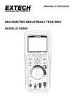
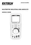
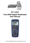
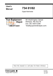
USER GUIDE TRUE RMS INDUSTRIAL MULTIMETER MODEL GX900 99 Washington Street Melrose, MA 02176 Phone 781-665-1400 Toll Free 1-800-517-8431 Visit us at www.TestEquipmentDepot.com Extech Instruments INTRODUCTION Thank you for selecting the Extech Model GX900 True RMS Multimeter with high measurement accuracy, quick A/D conversion rates, and built‐in datalogging and trending features. This device is shipped fully tested and calibrated and, with proper use, will provide years of reliable service. Extech Instruments is an ISO‐ 9001 certified company. Please visit the Extech Instruments website (www.extech.com) for the latest versions of Manuals, Software, Product updates, and other current information. KEY FEATURES Measures AC/DC Voltage and Current (including remote Clamp current), Resistance, Capacitance, Frequency (electrical and electronic), RPM, Duty Cycle, dBm/dBV, Diode, Continuity, and Temperature Built‐in datalogger and trend features store measurement data with convenient recall functionality Maximum reading (MAX) and Minimum Reading (MIN) memory features Reading HOLD feature for freezing displayed information (with Auto Hold) Intuitive TFT color LCD display and convenient keypad push‐button control On‐screen HELP utility for user hints and application information Quick A/D conversion sample rates with low pass AC filtering Internal real‐time calendar clock for time stamping Industrial strength meter housing 2 GX900-EU-EN V1.6 4/14 Extech Instruments TABLE OF CONTENTS INTRODUCTION ....................................................................................... 2 KEY FEATURES ......................................................................................... 2 TABLE OF CONTENTS ............................................................................... 3 SAFETY .................................................................................................... 6 INTERNATIONAL SAFETY SYMBOLS .......................................................... 6 IEC1010 OVERVOLTAGE INSTALLATION CATEGORIES ............................... 6 CAUTIONS ............................................................................................... 7 SAFETY INSTRUCTIONS – INPUT PROTECTION LIMITS .............................. 8 FCC COMPLIANCE .................................................................................... 9 DESCRIPTIONS ....................................................................................... 10 METER DESCRIPTION ............................................................................. 10 INPUT TERMINAL DESCRIPTION ............................................................. 10 KEYPAD DESCRIPTION ........................................................................... 11 LCD DISPLAY DESCRIPTION .................................................................... 12 QUICK START GUIDE .............................................................................. 13 MEASUREMENTS ................................................................................... 14 DC VOLTAGE MEASUREMENTS .............................................................. 14 AC VOLTAGE MEASUREMENTS .............................................................. 15 dBm/dBV AC MEASUREMENTS .............................................................. 15 LOW PASS FILTER FOR ACV MEASUREMENTS ........................................ 16 DC/AC MILLIVOLT MEASUREMENTS ...................................................... 16 3 GX900-EU-EN V1.6 4/14 Extech Instruments CURRENT CLAMP MEASUREMENTS ....................................................... 17 DC CURRENT MEASUREMENTS .............................................................. 18 AC CURRENT MEASUREMENTS .............................................................. 19 RESISTANCE MEASUREMENTS ............................................................... 20 CONTINUITY CHECK ............................................................................... 21 DIODE TEST ........................................................................................... 21 TEMPERATURE MEASUREMENTS .......................................................... 22 CAPACITANCE MEASUREMENTS ............................................................ 23 FREQUENCY, DUTY CYCLE, PULSE WIDTH, PERIOD MEASUREMENTS .... 23 RPM MEASUREMENTS ........................................................................... 24 COUNTER MEASUREMENTS ................................................................... 24 FUNCTIONS AND FEATURES ................................................................... 25 FUNCTION MENU BASICS ...................................................................... 25 THE ‘HELP’ UTILITY ................................................................................ 25 AUTOMATIC AND MANUAL RANGING ................................................... 26 AC AND DC SIGNALS .............................................................................. 26 MINIMUM (MIN) AND MAXIMUM (MAX) READINGS ............................ 27 CAPTURING PEAK VALUES ..................................................................... 28 RELATIVE MODE .................................................................................... 28 DATA HOLD AND AUTO‐HOLD MODE .................................................... 29 STORING INDIVIDUAL SCREEN‐SHOTS ................................................... 29 VIEWING MEMORY DATA ...................................................................... 29 VIEW TREND DATA ................................................................................ 30 RECORDING MEASUREMENTS (DATALOGGING) .................................... 31 4 GX900-EU-EN V1.6 4/14 Extech Instruments ZOOMING ON TREND DATA ................................................................... 32 METER SETUP OPTIONS ......................................................................... 32 RESET THE METER SETUP OPTIONS ........................................................ 32 METER INFORMATION SCREEN .............................................................. 33 SETTING THE EVENT THRESHOLD VALUE ............................................... 33 CHANGE CALIBRATION PASSWORD ....................................................... 33 CALIBRATION ACCESS ............................................................................ 34 BLUETOOTHTM CAPABILITY .................................................................... 34 GX900 SOFTWARE ................................................................................. 34 SETTING THE DATE AND TIME ............................................................... 35 AUTOMATIC POWER OFF ...................................................................... 35 TIME AND DATE FORMATS .................................................................... 36 NUMERIC FORMAT ................................................................................ 36 LANGAUGE FORMAT ............................................................................. 36 BATTERY AND FUSE REPLACEMENT ....................................................... 37 BATTERY REPLACEMENT ........................................................................ 37 FUSE REPLACEMENT .............................................................................. 38 SPECIFICATIONS ..................................................................................... 39 GENERAL SPECIFICATIONS ..................................................................... 39 ELECTRICAL SPECIFICATIONS ................................................................. 40 5 GX900-EU-EN V1.6 4/14 Extech Instruments SAFETY INTERNATIONAL SAFETY SYMBOLS This symbol, adjacent to another symbol or terminal, indicates the user must refer to the manual for further information. This symbol, adjacent to a terminal, indicates that, under normal use, hazardous voltages may be present Double insulation This symbol advises the user that the terminals so marked must not be connected to a circuit point at which the voltage with respect to earth ground exceeds (for this specific instrument) 1000VAC or VDC WARNING This symbol indicates a potentially hazardous situation, which if not avoided, could result in death or serious injury. CAUTION This symbol indicates a potentially hazardous situation, which if not avoided, could result in damage to the instrument. IEC1010 OVERVOLTAGE INSTALLATION CATEGORIES OVERVOLTAGE CATEGORY I Equipment of OVERVOLTAGE CATEGORY I is equipment for connection to circuits in which measures are taken to limit the transient over‐voltages to an appropriate low level. Examples include protected electronic circuits. OVERVOLTAGE CATEGORY II Equipment of OVERVOLTAGE CATEGORY II is energy‐consuming equipment to be supplied from the fixed installation. Examples include household, office, and laboratory appliances. OVERVOLTAGE CATEGORY III Equipment of OVERVOLTAGE CATEGORY III is equipment in fixed installations. Note – Examples include switches in the fixed installation and some equipment for industrial use with permanent connection to the fixed installation. OVERVOLTAGE CATEGORY IV Equipment of OVERVOLTAGE CATEGORY IV is for use at the origin of the installation. Examples include electricity meters and primary over‐current protection equipment. 6 GX900-EU-EN V1.6 4/14 Extech Instruments CAUTIONS Improper use of this meter can cause damage, shock, injury or death. Read and understand this user manual before operating the meter. Always remove the test leads before replacing the battery or fuses. Inspect the condition of the test leads and the meter itself for any damage before operating the meter. Use great care when making measurements if the voltages are greater than 25VAC rms or 35VDC. These voltages are considered a shock hazard. Warning! This is a class A equipment. This equipment can cause interference in residential areas; in these cases the operator may be required to take steps to avoid or minimize the interference. Always discharge capacitors and remove power from the device under test before performing Diode, Resistance, or Continuity tests. Voltage checks on electrical outlets can be difficult and misleading because of the uncertainty of connection to the recessed electrical contacts. Other means should be used to ensure that the terminals are not "live". If the equipment is used in a manner not specified by the manufacturer, the protection provided by the equipment may be impaired. This device is not a toy and must not reach children’s hands. It contains hazardous objects as well as small parts that the children could swallow. Do not leave batteries and packing material unattended; they can be dangerous in the hands of children. In the event that the device is going to be unused for an extended period of time, remove the batteries. Expired or damaged batteries can cause cauterization on contact with the skin. Always, therefore, use suitable gloves in such cases. Ensure that the batteries are not short‐circuited. Never incinerate batteries. 7 GX900-EU-EN V1.6 4/14 Extech Instruments SAFETY INSTRUCTIONS – INPUT PROTECTION LIMITS This meter has been designed for safe use, but must be operated with caution. The rules listed in this safety section must be carefully followed for safe operation. 1. NEVER apply voltage or current to the meter that exceeds the specified maximum: Input Protection Limits Function Maximum Input V DC or V AC 1000V DC/AC rms mA AC/DC 800mA 1000V fast acting fuse A AC/DC 10A 1000V fast acting fuse Frequency, Resistance, Capacitance, Duty Cycle, Diode 1000VDC/AC rms Test, Continuity Temperature 1000VDC/AC rms 2. USE EXTREME CAUTION when working with high voltages. 3. DO NOT measure voltage if the voltage on the "COM" input jack exceeds 1000V above earth ground. 4. NEVER connect the meter leads across a voltage source while the function switch is in the current, resistance, or diode mode. Doing so can damage the meter. 5. ALWAYS discharge filter capacitors in power supplies and disconnect the power when making resistance or diode tests. 6. ALWAYS turn off the power and disconnect the test leads before opening the covers to replace the fuse or batteries. 7. NEVER operate the meter unless the back cover and the battery and fuse covers are in place and fastened securely. 8. If the equipment is used in a manner not specified by the manufacturer, the protection provided by the equipment may be impaired. 8 GX900-EU-EN V1.6 4/14 Extech Instruments FCC COMPLIANCE This device complies with part 15 of the FCC Rules. Operation is subject to the following two conditions: 1. This device may not cause harmful interference. 2. This device must accept any interference received, including interference that may cause undesired operation. This equipment has been tested and found to comply with the limits for a Class B digital device, pursuant to part 15 of the FCC Rules. These limits are designed to provide reasonable protection against harmful interference in a residential installation. This equipment generates, uses, and can radiate radio frequency energy and, if not installed and used in accordance with the instructions, may cause harmful interference to radio communications. However, there is no guarantee that interference will not occur in a particular installation. If this equipment does cause harmful interference to radio or television reception, which can be determined by turning the equipment off and on, the user is encouraged to try to correct the interference by one or more of the following measures: • Reorient or relocate the receiving antenna. • Increase the separation between the equipment and receiver. • Connect the equipment into an outlet on a circuit different from that to which the receiver is connected. • Consult the dealer or an experienced radio/TV technician for help. 9 GX900-EU-EN V1.6 4/14 Extech Instruments DESCRIPTIONS METER DESCRIPTION 1. LCD display 1 2. Sub‐function keys F1, F2, F3, and F4 3. Data HOLD button 4. MAX‐MIN memory button 5. Rotary Primary Function Select Switch 6. Input jack for Amperes (A) 2 3 4 12 11 10 7. Input jack mA, uA (milli‐ & micro‐Amperes) 8. Input jack (COM) negative 5 9. Input jack (positive) for all functions 6 10. Display Backlight control 9 11. Information button 12. Navigation arrow keys and OK confirmation button 7 8 Note: Battery compartment and tilt stand are located on the rear of the instrument INPUT TERMINAL DESCRIPTION All functions, excepting current, use the V and COM input terminals. Separate terminals are provided for current above 500mA and for current below 500mA. Input for 0 A to 10.00 A current Input for 0 A to 500 mA current measurements Return terminal for all measurements Input for voltage, continuity, resistance, diode test, conductance, capacitance 10 GX900-EU-EN V1.6 4/14 Extech Instruments KEYPAD DESCRIPTION The meter’s 12 push‐button keypad activates features, augments functions selected by the rotary switch, and allows the navigation of the displayed menu structure F1‐F2‐F3‐F4 keys Selects sub‐functions related to the currently selected primary mode set by the rotary switch Cursor buttons Use the cursor buttons to selected items in a menu tree, adjust display contrast, scroll information, and perform data entry HOLD button Freezes the displayed reading and, if desired, saves the screen shot. The HOLD button also accesses the AUTO HOLD feature which is detailed in this Instruction Manual MAX/MIN button Starts and stops the Maximum (MAX) and Minimum (MIN) reading memory OK button Confirms data entry Rotary Switch Selects the primary measurement function; for each, the meter presents a standard display for that function (range, measurement units, and modifiers). See table below: V~ AC voltage measurements V– DC and AC+DC voltage measurements mV DC(AC) millivolts, ac + dc millivolt, Temperature, Clamp Current measurements Resistance, Diode test, capacitance, continuity measurements Hz % Frequency and duty cycle measurements RPM Counter RPM, Counter measurements A AC, dc and ac + dc amps measurements mA AC, dc and ac + dc milliamps measurements uA AC, dc and ac + dc microampere measurements up to 5,000 μA INFO button Opens the information window Backlight button Selects backlight intensity from low to high. Also used to return from an auto‐power off condition 11 GX900-EU-EN V1.6 4/14 Extech Instruments LCD DISPLAY DESCRIPTION 1. Soft key labels indicate the function of the button just below the displayed label. 2. Bar graph Analog display for the input signal (See the "Bar Graph" section for more information). 3. Primary measurement display area* (minus sign indicates a negative reading). 4. Range indicates the meter’s present range and the ranging mode (auto or manual). 5. Battery level indicates the battery charge level. 6. Time indicates the time set for the internal clock. 7. Mode annunciators indicate the Meter's mode. 8. Mini‐measurement display shows the input value when the primary and secondary displays are busy with a menu screen or pop‐up message. Also shows the lightning bolt icon (when necessary) in this area. 9. Main display provides measurement information regarding the input signal. 10. Date indicates the date set for the internal clock. 11. Beeper indicates the Meter’s audible feedback is enabled (this is not associated with the continuity beeper). 12. Unit indicates the units of measure. Auxiliary Units indicates measurements that use factors instead of units (such as Crest Factor). 13. Blue tooth indicates communication link activity. 14. Relative indicates that the displayed value is relative to a stored reference value. 15. Secondary display shows secondary measurement information concerning the input signal. *The Primary display area indicates the most important value of the selected function. The secondary display contains the bar graph and other values that may be measured in addition to the primary function (for example, frequency measurements along with the primary AC voltage measurement). 12 GX900-EU-EN V1.6 4/14 Extech Instruments QUICK START GUIDE Step One: Ensure that batteries are installed and are fresh Step Two: Carefully read the Safety section of this Instruction Manual Step Three: Check the Table of Contents to find the section of this Instruction Manual related to the desired test Step Four: Connect the test leads to the meter and to the device under test as described in this Instruction Manual’s section related to the test in question Step Five: Safely perform the test as described in this Instruction Manual Step Six: Read the measurement value on the LCD display Step Seven: Carefully disconnected the meter’s test leads from the circuit or device under test Step Eight: Read the section of this Instruction Manual entitled Features and Functions to learn more about the multitude of meter uses and features Step Nine: Disconnect the test leads from the circuit under test and from the meter and switch OFF the meter before storing. 13 GX900-EU-EN V1.6 4/14 Extech Instruments MEASUREMENTS WARNING: Risk of electrocution. High‐voltage circuits, both AC and DC, are very dangerous and should be measured with great care. 1. ALWAYS turn the function switch to the OFF position when the meter is not in use. 2. If OL appears in the display during a measurement, the value exceeds the selected range. Change to a higher range or use the Auto range mode. DC VOLTAGE MEASUREMENTS CAUTION: Do not measure DC voltages if a motor on the circuit is being switched ON or OFF. Large voltage surges may occur that can damage the meter. 1. Set the function switch to the V‐ position. 2. Insert the black test lead banana plug into the negative COM jack. Insert the red test lead banana plug into the positive V jack. 3. Touch the black test probe tip to the negative side of the circuit. 4. Touch the red test probe tip to the positive side of the circuit. 5. Read the voltage in the display. 14 GX900-EU-EN V1.6 4/14 Extech Instruments AC VOLTAGE MEASUREMENTS WARNING: Risk of Electrocution. The probe tips may not be long enough to contact the live parts inside some 240V outlets for appliances because the contacts are recessed deep in the outlets. As a result, the reading may show 0 volts when the outlet actually has voltage on it. Make sure the probe tips are touching the metal contacts inside the outlet before assuming that no voltage is present. CAUTION: Do not measure AC voltages if a motor on the circuit is being switched ON or OFF. Large voltage surges may occur that can damage the meter. 1. Set the function switch to the V~ position. 2. Insert the black test lead banana plug into the negative COM jack. Insert red test lead banana plug into the positive V jack. 3. Touch the black test probe tip to the neutral side of the circuit. Touch the red test probe tip to the “hot” side of the circuit. 4. Read the voltage in the display. dBm/dBV AC MEASUREMENTS The meter is capable of displaying AC voltage as a dB value; relative to 1 milli‐watt (dBm), relative to 1V (dBV), or to a custom reference value. 1. Set the function switch to the V~ position 2. Press the F1 key (MENU) on the LCD and then navigate to the dBm/dBV field using the arrow keys and then press OK. 3. Navigate to the menu item labeled dBm and then press OK. 4. Insert the black test lead banana plug into the negative COM jack. Insert red test lead banana plug into the positive V jack. 5. Touch the black test probe tip to the neutral side of the circuit. Touch the red test probe tip to the “hot” side of the circuit. 6. Read the dBm in the primary display area and read the Voltage in the secondary display area. 15 GX900-EU-EN V1.6 4/14 Extech Instruments LOW PASS FILTER FOR ACV MEASUREMENTS The meter is equipped with a Low Pass Filter for AC measurements. To activate the filter please follow the steps below: 1. Set the rotary switch to the V~ position 2. Press the F1 key (MENU) 3. Move the menu selector to the LOW PASS field and then press OK 4. Select LPF (Low Pass Filter) and then press OK 5. Press the F3 key (RANGE) and then press the F2 key (MANUAL) 6. Move the menu selector to the 500V field and press the OK key DC/AC MILLIVOLT MEASUREMENTS CAUTION: Do not measure DC/AC voltages if a motor on the circuit is being switched ON or OFF. Large voltage surges may occur that can damage the meter. 1. Set the function switch to the mV position. 2. Press the F1 key (MENU), move the menu selector to the menu item labeled mVDC or mVAC, and then press the OK key 3. Select mVDC or mVAC from the key options and press the OK key. 4. Insert the black test lead banana plug into the negative COM jack. 5. Insert the red test lead banana plug into the positive V jack. 6. Touch the black test probe tip to the negative side of the circuit. 7. Touch the red test probe tip to the positive side of the circuit. 8. Read the voltage in the display. 16 GX900-EU-EN V1.6 4/14 Extech Instruments CURRENT CLAMP MEASUREMENTS 1. This meter offers remote current clamp measurement functionality. 2. Set the rotary switch to the mV position. 3. Press the F1 key (MENU), move the menu selector to the item labeled CLAMP DC/AC, and then press the OK key. 4. Select the item labeled RANGE (0.1~100mV/A) and then press the OK key. 5. Connect the remote clamp to the input terminal jacks ensuring proper polarity. Insert the clamp’s negative lead into the negative COM jack and connect the clamp’s positive lead into the meters positive V jack. 6. Read the measurement in the display. 17 GX900-EU-EN V1.6 4/14 Extech Instruments DC CURRENT MEASUREMENTS CAUTION: Do not make 20A current measurements for longer than 30 seconds. Exceeding 30 seconds may cause damage to the meter and/or the test leads. 1. Insert black test lead banana plug into the negative COM jack. 2. For current measurements up to 5000µA DC, set the function switch to the µA position and insert the red test lead banana plug into the µA/mA jack. Press the F1 key (MENU) and select uADC, Press the OK key. 3. For current measurements up to 500mA DC, set the function switch to the mA position and insert the red test lead banana plug into the µA/mA jack. Press the F1 key (MENU) and select mADC, Press the OK key. 4. For current measurements up to 10A DC, set the function switch to the 10A position and insert the red test lead banana plug into the 10A jack. Press the F1 key (MENU) and select ADC, Press the OK key. 5. Remove power from the circuit under test, then open up the circuit at the point where current is to be measured. 6. Touch the black test probe tip to the negative side of the circuit. 7. Touch the red test probe tip to the positive side of the circuit. 8. Apply power to the circuit. 9. Read the current in the display. 18 GX900-EU-EN V1.6 4/14 Extech Instruments AC CURRENT MEASUREMENTS CAUTION: Do not make 20A current measurements for longer than 30 seconds. Exceeding 30 seconds may cause damage to the meter and/or the test leads. 1. Insert the black test lead banana plug into the negative COM jack. 2. For current measurements up to 5000µA AC, set the function switch to the µA position and insert the red test lead banana plug into the µA/mA jack. Press the F1 key (MENU) and select uAAC, Press the OK key. 3. For current measurements up to 500mA AC, set the function switch to the mA position and insert the red test lead banana plug into the µA/mA jack. Press the F1 key (MENU) and select mAAC, Press the OK key. 4. For current measurements up to 10A AC, set the function switch to the 10A position and insert the red test lead banana plug into the 10A jack. Press the F1 key (MENU) and select AAC, Press the OK key. 5. Press the key labeled MENU, move the menu selector to the item labeled AC, and then press the OK key 6. Remove power from the circuit under test, then open up the circuit at the point where current is to be measured. 7. Touch the black test probe tip to the neutral side of the circuit. Touch the red test probe tip to the “hot” side of the circuit. 8. Apply power to the circuit. 9. Read the current in the display. 19 GX900-EU-EN V1.6 4/14 Extech Instruments RESISTANCE MEASUREMENTS WARNING: To avoid electric shock, disconnect power to the unit under test and discharge all capacitors before taking any resistance measurements. Remove the batteries and unplug the line cords. 1. Set the function switch to the Ω CAP position. 2. Insert the black test lead banana plug into the negative COM jack. 3. Insert the red test lead banana plug into the positive Ω jack 4. Touch the test probe tips across the circuit or part under test. It is best to disconnect one side of the part under test so the rest of the circuit will not interfere with the resistance reading. 5. Read the resistance in the display. 20 GX900-EU-EN V1.6 4/14 Extech Instruments CONTINUITY CHECK WARNING: To avoid electric shock, never measure continuity on circuits or wires that have voltage on them. 1. Set the function switch to the Ω CAP position. 2. Press the F1 key (MENU), move the menu selector to the RESISTANCE, and then press the OK key 3. Move the menu selector to the item labeled CONTINUITY and press the OK key 4. Insert the black lead banana plug into the negative COM jack. 5. Insert the red test lead banana plug into the positive jack. 6. Touch the test probe tips to the circuit or wire under test. 7. If the resistance is less than approximately 35 Ω, the audible signal will sound. If the circuit is open, the display will indicate OL. DIODE TEST 1. Set the function switch to the Ω CAP position 2. Press the F1 key (MENU), move the menu selector to the DIODE field, and then press the OK key 3. Move the menu selector to the item labeled DIODE and press the OK key 4. Insert the black test lead banana plug into the negative COM jack and the red test lead banana plug into the positive V jack. 5. Touch the test probes to the diode under test. Forward voltage will typically indicate 0.400 to 3.200V. Reverse voltage will indicate OL. Shorted devices will indicate near 0V and an open device will indicate OL in both polarities. 21 GX900-EU-EN V1.6 4/14 Extech Instruments TEMPERATURE MEASUREMENTS 1. Set the function switch to the TEMP position. 2. Press the F1 key (MENU), move the menu selector to the item labeled TEMP, and then press the OK key 3. Move the menu selector to menu item labeled FAHRENHEIT, Celsius, or Kelvin and then press the OK key 4. Insert the Temperature Probe into the input jacks ensuring correct polarity. 5. Touch the Temperature Probe head to the device under test. Maintain contact with the device until the reading stabilizes (about 30 seconds). 6. Read the temperature in the display. To input a temperature offset value, press the F3 key (OFFSET). A message box will appear showing the currently selected offset value. Use the right/left arrow keys to position the cursor over one of the digits (or the polarity sign). Then use the up/down arrows to edit the selected digit or polarity sign. With the desired value displayed, press the F1 key (OK) to confirm the temperature offset. Note: The temperature probe is fitted with a type K mini connector. A mini connector to banana connector adaptor is supplied for connection to the input banana jacks. The adapter connects to COM (‐) and V (+). Note: The temperature range of the supplied thermocouple probe is ‐20 to 250°C (‐4 to 482°F) 22 GX900-EU-EN V1.6 4/14 Extech Instruments CAPACITANCE MEASUREMENTS WARNING: To avoid electric shock, disconnect power to the unit under test and discharge all capacitors before taking any capacitance measurements. Remove the batteries and unplug the line cords. 1. Set the rotary function switch to the CAP position. 2. Press the F1 key (MENU), move the menu selector to the menu item labeled CAPACITANCE, and then press the OK key. 3. Select CAPACITANCE and then press the OK key. 4. Insert the black test lead banana plug into the negative COM jack. 5. Insert the red test lead banana plug into the positive V jack. 6. Touch the test leads to the capacitor to be tested. 7. Read the capacitance value in the display FREQUENCY, DUTY CYCLE, PULSE WIDTH, and PERIOD MEASUREMENTS (ELECTRONIC) 1. Set the rotary function switch to the Hz/% position. 2. Press the F1 key (MENU), move the menu selector to the menu item of your choice, either FREQUENCY(Hz), DUTY CYCLE, PULSE WIDTH, or PERIOD, and then press the OK key. 3. Insert the black lead banana plug into the negative COM jack and the red test lead banana plug into the positive Hz jack. 4. Touch the test probe tips to the circuit under test. 5. Read the measurement on the display. 23 GX900-EU-EN V1.6 4/14 Extech Instruments RPM MEASUREMENTS 1. Set the rotary function switch to the RPM position. 2. Insert the black lead banana plug into the negative COM jack and the red test lead banana plug into the positive V jack. 3. Touch the test probe tips to the circuit under test. 4. Read the RPM value on the display. COUNTER MEASUREMENTS 1. Set the rotary function switch to the RPM position. 2. Press the F1 key (MENU), move the menu selector to the item labeled COUNTER, and then press the OK key 3. Move the menu selector to the item labeled START and press the OK key 4. Insert the black test lead into the negative COM jack and the red test lead into the positive V jack. 5. Touch the test probe tips to the circuit under test. 6. Read the Period value on the display. 7. To set the Count Threshold press the F1 key (MENU), move the menu selector to the item labeled COUNTER, and press the OK key 8. Move the menu selector to the menu item labeled THRESHOLD and press the OK key 9. Enter 1 or 2 or 3 using the arrow keys and then press the F1 key to save. Press the F1 key to return to the measure screen. 24 GX900-EU-EN V1.6 4/14 Extech Instruments FUNCTIONS AND FEATURES FUNCTION MENU BASICS Each primary measurement function (selected by rotary dial position) has a number of optional sub‐functions or modes accessed by pressing the F1 key (MENU). A typical menu is shown here. Menu selection is indicated by the dark colored square (designated as the ‘menu selector’ in this Instruction Manual) to the left of the menu item. Use the four front panel cursor buttons (left, right, up, and down) to position the menu selector next to a menu item. As the menu selector moves between menu items, the four F keys and OK key change to reflect the available functions and/or modes available for the selection menu item. THE ‘HELP’ UTILITY While operating the meter, additional information regarding a selected function, a front‐panel button, or a menu may be needed. Press the INFO key to open an information window that lists topics covering the functions and modifiers that are available at the time the button is pressed. Each topic provides a brief explanation on a meter function or feature. The number of informational topics displayed at any one time may exceed the display area. Use the keys labeled NEXT and PREV to move from topic to topic. Use the key labeled MORE, UP, and DOWN to scroll through the information a full screen at a time. 25 GX900-EU-EN V1.6 4/14 Extech Instruments AUTOMATIC AND MANUAL RANGING Press the F3 key (RANGE) to open the Range menu. Press F1 key (AUTO) to enable the Auto Range mode. Press F2 key (MANUAL) to enable the Manual Range mode. In the Manual Range mode, move the menu selector to the desired range. AC AND DC SIGNALS This meter is capable of displaying both AC and DC signal components (voltage or current) as two separate readings or one AC+DC (RMS) value combined. The meter displays AC and DC combinations three ways: DC displayed over AC (DC, AC) AC displayed over DC (AC, DC) AC combined with DC (AC+DC) Select one of the above combinations using the FUNCTION and MODE menu as described in the steps below: 1. With the rotary switch set to V, mV, A, mA, or uA press the key labeled MENU 2. Move the menu selector to the menu item labeled MATH 3. Press OK 4. The three labels (AC+DC, AC/DC, and DC/AC) will appear 5. Move the menu selector to the desired menu label 6. Press OK While in any of the three modes described above Peak Measurements, Frequency, Duty Cycle, MAX‐MIN, Relative %, and Period Measurements are not available for use. 26 GX900-EU-EN V1.6 4/14 Extech Instruments MINIMUM (MIN) AND MAXIMUM (MAX) READINGS The MIN‐MAX recording mode captures minimum, maximum, and average measurement values. When the measurement falls below the recorded minimum value or above the recorded maximum value, the meter beeps and records the new value. The meter stores the elapsed time since the recording session was started at the same time. The MIN‐MAX mode also calculates an average of all readings taken since the MIN‐MAX mode was activated. Average mode is useful for capturing intermittent readings and recording readings while equipment operation precludes watching the meter. The MIN‐MAX mode is useful when recording power supply surges, in‐rush currents, and finding intermittent failures. Response time is the length of time an input must remain at a new value to be captured as a possible new minimum or maximum valued. To activate the MIN‐MAX mode, press the MIN‐MAX button; the display will indicate the MIN‐MAX values at the top of the measurement page. The start date and time are indicated at the bottom of the measurement page. In addition, the recorded MIN‐ MAX‐AVG values appear in the secondary display with their respective elapsed timers. To stop a MIN‐MAX recording session press the key labeled STOP. The summary information in the display freezes and the keys change function to allow saving the collected data. Press the key labeled ‘CLOSE’ to discard the collected data and return to the normal operating mode. To save the MIN‐MAX screen data, the MIN‐MAX session must be ended by pressing the key labeled STOP. After pressing STOP, press the key labeled SAVE. A dialogue box will open prompting for a filename (a name is automatically proposed which can be accepted or changed by the user). Press the key labeled SAVE. Press the key labeled RESTART while MIN‐MAX is running stops the MIN‐MAX session, discards all MIN‐MAX data, and starts a new MIN‐MAX recording session. 27 GX900-EU-EN V1.6 4/14 Extech Instruments CAPTURING PEAK VALUES To activate the PEAK Mode, press the F1 key (MENU). Move the menu selector to the menu item labeled PEAK/CREST F (Crest Factor) and then press the OK key. Move the menu selector to the PEAK or the CREST F label and then press OK to start the PEAK recording session. RELATIVE MODE To activate the Relative mode, press the F1 key (MENU) and move the menu selector next to the menu item labeled REL/REL% and then press the OK key. Move the menu selector to the REL or the REL% label and press OK to start the Relative mode. If the meter is currently in the Relative mode, pressing REL% causes the meter to switch OFF the Relative mode and display Relative percent. 28 GX900-EU-EN V1.6 4/14 Extech Instruments DATA HOLD AND AUTO‐HOLD MODE To freeze the display for any function, press the HOLD key. Pressing the F2 key (AUTO HOLD) activates the Auto Hold mode (if the meter is not in the PEAK, MIN‐MAX, or Record modes). Auto‐Hold monitors the input signal and updates the display and, if enabled, sounds the beeper each time a new stable measurement is detected. A stable measurement is one that does not vary more than a selected adjustable percentage (Auto‐Hold threshold) for at least one second. The meter filters open lead conditions so that the meter leads can be moved between test points without triggering a display update. STORING INDIVIDUAL SCREEN‐SHOTS For all measurement functions, a snapshot of the screen data is saved by pressing the key labeled SAVE. VIEWING MEMORY DATA Viewing data stored in the meter’s memory is performed through the SAVE menu as described below: 1. Press the F2 key (SAVE). 2. Position the menu selector on MEMORY and press the OK key. 3. Position the menu selector on VIEW and press the OK key. 4. Position the menu selector on LOG and press the OK key. 5. Press F1 (PREV) or F2 (NEXT) to view your saved data sets. 29 GX900-EU-EN V1.6 4/14 Extech Instruments VIEW TREND DATA Viewing data stored in the meter’s memory is performed through the SAVE menu as described below: 1. Press the F2 key (SAVE) and select menu item MEMORY and Press the OK key. 2. Select menu item VIEW and Press the OK key. 3. Select menu item LOG and Press the OK key. If there are previously stored records, press the F1 key (PREV) to page through them or press the F2 key (NEXT) to scroll in the opposite direction. Press F4 (CLOSE) to return the meter to the normal operating mode. Press the F3 key (TREND) to display the recorded data in a trend‐plot view. Press the F2 key (DELETE) to clear recorded data. Press the F3 key (SUMMARY) to get back to the data summary and Press F4 key (CLOSE) to return to normal operating mode. 30 GX900-EU-EN V1.6 4/14 Extech Instruments RECORDING MEASUREMENTS (DATALOGGING) The meter’s datalogger collects measurement information over a user‐specified duration (sampling rate). A datalogging recording session is made up of one or more measurement records with each record including a measurement summary representing the duration of the recording session. 1. Set the meter rotary switch to the meter setting to be logged. (Example V~ to log AC volts). 2. Connect the black lead to the COM jack and the Red lead to the V jack. 3. Datalog: Press the F2 key (SAVE) and then position the menu selector next to the menu item LOG and press the OK key to open the datalogging configuration screen. 4. The recording session Duration and Sample rate are user‐programmable. These two parameters interact in that one setting variable may adjust the other to fit the recording session in the available memory. Adjust these by using the up and down menu arrows to select either Duration or Sample rate. Press OK key to select. Press F1 key (EDIT) to edit the parameter, press the OK key to enable editing. Use the left and right menu arrow keys to select the unit to change, press F1 key (OK) to save your changes. The percentage of memory available at the beginning of a recording session is displayed below the duration and sample interval settings. 5. Press the F2 key (START) to start datalogging. 6. To change either of the two recording variables use the cursor buttons to position the menu selector next to the desired menu item and press the key labeled EDIT. Use the arrow keys to move between, and to set, each digit of the selected variable. 7. Press the key labeled START to start recording. 8. The recording session will continue until the allocated memory is consumed, the batteries expire, the rotary switch is moved, or the session is terminated by pressing the key labeled STOP. 31 GX900-EU-EN V1.6 4/14 Extech Instruments ZOOMING ON TREND DATA While viewing trend data, press ZOOM to zoom in or out respectively on the data around the cursor. Each press reduces the x‐axis time period by one half in order to reveal more detail. Each press doubles the time period until all of the recorded data is displayed. The zoom level is displayed in the upper‐right hand corner of the display. METER SETUP OPTIONS The meter offers a number of setup options and preset features such as date and time formats, battery save mode timeouts, and the displayed language. Some options affect general operations and are active in all functions while others are limited to one function or one group of functions. Meter information such as serial number, model, etc. is also available in the Setup mode. Access to the setup options is available by pressing the F4 key (SETUP). RESET THE METER SETUP OPTIONS The meter’s setup options can be reset to factory default conditions through the Setup menu. 1. Open the setup menu by pressing the F4 key (SETUP). 2. Position the menu selector next to the item labeled RESET and then press the OK key 3. Position the menu selector next to the item labeled SETUP and then press the OK key, press the OK key again. 4. A message will appear asking “Reset settings to Factory Defaults?” to confirm the Reset action. Press the F1 key (OK) or the F4 key (Cancel) to cancel the reset. 32 GX900-EU-EN V1.6 4/14 Extech Instruments METER INFORMATION SCREEN The meter INFO selection lists the serial number, model number, firmware version, calibration date, calibration counter, operator name, and company name. 1. Open the Setup menu by pressing the F4 key (SETUP). 2. Position the menu selector next to the menu item labeled INSTRUMENT and press OK 3. Position the menu selector next to the menu item labeled METER INFO and press OK, press the OK key again for meter information. SETTING THE EVENT THRESHOLD VALUE 1. Press the F4 key (SETUP) to access the setup menu 2. Position the menu selector next to the menu item labeled LOGGING and press OK 3. Position the menu selector next to the menu item labeled THRESHOLD and press OK 4. Position the menu selector next to the menu item labeled EDIT and press OK 5. Use the up and down arrow keys to change the event threshold values 6. With the desired value selected, press theF1 key (OK) to confirm the change or press the F4 key (Cancel) to cancel the change. CHANGE CALIBRATION PASSWORD The Calibration selection allows a qualified calibration technician to enter a password that grants access to the meter for calibration purposes. 1. Press the F4 key (SETUP) to access the Setup menu. 2. Using the cursor buttons, move the menu selector next to the item labeled Calibration and press OK. 3. Select PASSWORD and press OK. 4. Select EDIT and press OK. 5. Using the menu arrow keys enter a password and Click F1 key (OK) of F4 key (CANCEL). Note: default password is 1234 33 GX900-EU-EN V1.6 4/14 Extech Instruments CALIBRATION ACCESS The Calibration selection allows a qualified calibration technician to enter a password that grants access to the meter for calibration purposes. 1. Press the F4 key (SETUP) to access the Setup menu. 2. Using the cursor buttons, move the menu selector next to the item labeled Calibration and press OK. 3. Select menu item CALIBRATE and press OK. 4. Select CALIBRATE and press OK. 5. Input the current password using the menu keys and press F1 key (OK) or press the F4 key (CANCEL). Calibration instructions are only available to qualified certified technicians. Contact Extech Instruments for further information concerning calibration instructions BLUETOOTHTM CAPABILITY A Bluetooth communication link can be used to connect to the GX900 software. It will also allow you to monitor the meter from an Android device using ExView™. 1. Open the setup menu by pressing the F4 key (SETUP). 2. Position the menu selector next to the INSTRUMENT label and press OK 3. Position the menu selector next to the COMMUNICATE label and press OK 4. Press the F1 key (START) to turn on the Bluetooth™ signal. 5. Repeat steps 1~3 and then press the F2 key (STOP) to turn off the Bluetooth™ signal. Note: when the meter is shut off and then back on, the Bluetooth signal will have to be turned back on manually. GX900 SOFTWARE The GX900 meter comes with software that will allow you to capture measured data in Real Time and download logged data from the GX900 to the software. Refer to the software’s help file for instructions for use. 34 GX900-EU-EN V1.6 4/14 Extech Instruments SETTING THE DATE AND TIME The meter’s internal clock is used for time‐stamping and for general informational purposes. To change the date and time, as well as the display format, press the F4 key (SETUP) and then follow the steps below: 1. Position the menu selector next to the item labeled DISPLAY and press OK. 2. Position the menu selector next to the item DATE/TIME and press the OK key. 3. Position the menu selector next to either the SET DATE or the SET TIME item and the press the OK key. 4. Using the left and right arrows position the cursor on the date or time element to adjust it. 5. Use the up and down arrows to change the selected date or time values. 6. Press the F1 key (OK) to complete and confirm the actions. AUTOMATIC POWER OFF 1. Open the Setup menu by pressing the F4 Key (SETUP). 2. Position the menu selector next to INSTRUMENT and press OK. 3. Position the menu selector next to SETTINGS and press OK. 4. Position the menu selector next to the item labeled POWER OFF and press OK. 5. To set the Auto Power OFF time interval, use the up and down arrows to select the time in minutes (05 to 60). 6. Set the time to zero (00) to disable the Auto Power OFF feature. 7. Press the F1 key (OK) to confirm the selection. 8. Press the F4 key (CANCEL) to return to the normal operating mode without saving the edit. 35 GX900-EU-EN V1.6 4/14 Extech Instruments TIME AND DATE FORMATS 1. Press the f4 key (SETUP). 2. Position the menu selector next to the item labeled DISPLAY and press OK. 3. Position the menu selector next to the item labeled FORMAT and press OK 4. Position the menu selector next to the item labeled TIME FORMAT or DATE FORMAT and press OK to begin editing 5. TIME FORMAT – select F1 (24 HOUR) or F2 (12 HOUR). DATE FORMAT – select F1(MM/DD/YY) or F2 (DD/MM/YY). Press F3 (CANCEL) to exit without changing the format. NUMERIC FORMAT 1. Press the F4 key (SETUP). 2. Position the menu selector next to the item labeled DISPLAY and press OK. 3. Position the menu selector next to the item labeled FORMAT and press OK 4. Position the menu selector next to the item labeled NUMERIC and press OK. 5. Select F1 (0.000) or F2 (0,000) or F4 (CANCEL). LANGAUGE FORMAT 1. Press the F4 key (SETUP). 2. Position the menu selector next to the item labeled DISPLAY and press OK. 3. Position the menu selector next to the item labeled FORMAT and press OK 4. Position the menu selector next to the item labeled LANGAUGE and press OK. 5. Select F1 (ENG) or F4 (CANCEL). 36 GX900-EU-EN V1.6 4/14 Extech Instruments BATTERY AND FUSE REPLACEMENT BATTERY REPLACEMENT When the low battery icon appears on the display replace the batteries as described below: 1. Switch the meter off and remove the test leads from the meter’s input jacks 2. Open the battery compartment door by removing the 2 screws. 3. Replace the batteries; please observe battery orientation and polarity 4. Replace the battery compartment cover Battery Safety Reminders Please dispose of batteries responsibly Observe local, state, and federal regulations with regard to battery disposal. Never dispose of batteries in a fire. Batteries may explode or leak. Never mix battery types. Always install new batteries of the same type. Never dispose of used batteries or rechargeable batteries in household waste. As consumers, users are legally required to take used batteries to appropriate collection sites, the retail store where the batteries were purchased, or wherever batteries are sold. Disposal: Do not dispose of this instrument in household waste. The user is obligated to take end‐of‐life devices to a designated collection point for the disposal of electrical and electronic equipment. 37 GX900-EU-EN V1.6 4/14 Extech Instruments FUSE REPLACEMENT 1. Switch the meter off and remove the test leads from the meter’s input jacks 2. Remove the battery compartment cover. 3. Remove the fuse from the battery compartment by first carefully prying one end loose and then sliding the fuse from its bracket 4. Install only specified replacement fuses 5. Replace the battery compartment cover 800mA/1000V ceramic ‐ 6.3mm x 32mm (SIBA 7017240.0,8) 10A/1000V ceramic ‐ 10mm x 38mm (SIBA 5019906.10) 38 GX900-EU-EN V1.6 4/14 Extech Instruments SPECIFICATIONS GENERAL SPECIFICATIONS Enclosure Shock (Drop Test) Diode Test Continuity Check PEAK Temperature Sensor Input Impedance AC Response ACV Bandwidth Double molded, waterproof 2m (6.5 ft) Test current 0.9mA maximum, open circuit voltage 3.2V DC (typ.) Audible signal will sound if the resistance is less than 25 ohms (approx.), test current <0.35mA Captures peaks >1ms Requires type K thermocouple >10M ohms VDC; >9M ohms VAC True RMS 50Hz to 100,000Hz Crest Factor <3 at full scale up to 500V, decreasing linearly to <1.5 at 1000V Display 50,000 count backlit liquid crystal display with bar-graph Memory 2,500 memory locations Over-range indication “OL” is displayed Auto Power Off After 30 minutes of inactivity (approximately) with disable feature Polarity Automatic (no indication for positive); Minus (-) sign for negative Measurement Rate 20 times per second Low Battery Battery icon displayed when battery drops below operating voltage FF 0.8A/1000V 6.3x32mm, (SIBA 7017240.0,8) FF 10A/1000V 10x38mm, (SIBA 5019906.10) 5°C to 40°C (41°F to 104°F) Max 80% up to 31°C (87°F) decreasing linearly to 50% at 40°C (104°F) -20°C to 60°C (-4°F to 140°F), <80% 2000m (7000 ft.) max. This meter protected by double insulation per EN61010-1 and IEC61010-1 2nd Edition (2001) to Category IV 600V and Category III 1000V; Pollution Degree 2. The meter also meets UL 61010-1, 2nd Edition (2004), CAN/CSA C22.2 No. 61010-1 2nd Edition (2004), and UL 61010B -2-031, 1st Edition (2003) Version 2.0+EDR, Frequency range 2400 MHz…2483.5 MHz (ISM-Band), Guard band 2 MHz < F < 3.5 MHz Modulation method GFSK,1 Mbps,0.5 Gaussian; Receiving signal range -82 to -20 dBm Transmission power Minimum: -18dBm to +4 dBm ANSI / NEDA- 5004LC,IEC-CR2032; Normal Voltage: 3.0 Volts; Typical Capacity: 240 mAh ; Storage 5 Year Chemical type: Lithium polymer, Standard: GB/T 235 x 108 x 63.5mm (9.25 x 4.25 x 2.5”) 839g (1.85 lbs.) Fuses Operating Temperature Operating Humidity Storage Temp/Humidity Operating Altitude Safety Bluetooth specification Built-in lithium Dimensions Weight 39 GX900-EU-EN V1.6 4/14 Extech Instruments ELECTRICAL SPECIFICATIONS Function DC Voltage Range 50mV [¹] 500mV [¹] 5V 50V 500V 1000V Resolution 0.001mV 0.01mV 0.0001V 0.001V 0.01V 0.1V Accuracy (0.05% + 20) (0.025% + 5digits) (0.025% + 5digits) (0.025% + 5digits) (0.05% + 5digits) (0.1% + 5) [1] Use the relative mode (REL Q) to compensate for offsets. Function AC Voltage Range Resolution 50mV 500mV 5V 50V 500V 1000V 0.001mV 0.01mV 0.0001V 0.001V 0.01V 0.1V Accuracy 50 to 10000Hz 50/60Hz(0.3% + 25) <1KHz(0.5% + 25) <5KHz(3% + 25) Accuracy for all AC voltage ranges are specified from 5% of range to 100% of range Function (AC+DC) Range Resolution 50mV 500mV 5V 50V 500V 1000V 0.001mV 0.01mV 0.0001V [¹] 0.001V 0.01V 0.1V Accuracy 0 to 1000Hz <1KHZ(1% + 25) <10KHZ(3.5% + 25) [1] Add 1% above 5k Function DC Current Function AC Current Range 500µA 5000µA 50mA 500mA 10A Range Resolution 0.01µA 0.1µA 0.001mA 0.01mA 0.001A Resolution 500µA 5000µA 50mA 500mA 10A 0.01µA 0.1µA 0.001mA 0.01mA 0.001A Accuracy 0.1%+20 0.15%+20 0.3%+20 Accuracy 50 to 10000Hz 50/60Hz (0.6% + 25) <1KHz (1.5% + 25) <10KHz (3% + 25) Accuracy for all AC current ranges are specified from 5% of range to 100% of range 40 GX900-EU-EN V1.6 4/14 Extech Instruments Function (AC+DC) Function AC Voltage (5000+ count) Range Resolution 500µA 5000µA 50mA 500mA 10A Range 0.01µA 0.1µA 0.001mA 0.01mA 0.001A Resolution 50mV 500mV 5V 50V 0.001mV 0.01mV 0.0001V 0.001V Accuracy 0 to 1000Hz (1.0% + 25) (1.5% + 40) Accuracy 5K-100K (5.0% + 40) (6.0% + 40) NOTE: Accuracy is stated at 18 to 28°C (65 to 83°F) and < 75% RH for calibration using a pure sine wave. Function Resistance Range 50Ω[1] 500Ω[1] 5kΩ 50kΩ 500kΩ 5MΩ 50MΩ Resolution 0.001Ω 0.01Ω 0.0001kΩ 0.001kΩ 0.01kΩ 0.0001MΩ 0.001MΩ Accuracy 0.5%+20 0.05%+10 0.05%+10 0.2%+10 0.2%+20 2%+20 [1] Use the relative mode (REL Q) to compensate for offsets. Function Capacitance Range 5nF[¹] 50nF[¹] 500nF 5µF 50µF 500µF 10mF Resolution 0.001nF 0.01nF 0.1nF 0.001µF 0.01µF 0.1µF 0.01mF Accuracy ±(2% + 40) ±(2% + 40 digits) ±(5% +40 digits) [1] With a film capacitor or better, use relative mode (REL ∆ ) to zero residual. 41 GX900-EU-EN V1.6 4/14 Extech Instruments Function Frequency (electronic) Frequency (electrical) Function Duty Cycle Function RPM Count Clamp(DC) Clamp(AC) Function Temperature (type-K) Range Resolution Accuracy 50Hz 0.001Hz ±(0.01% + 10) 500Hz 0.01Hz 5kHz 0.0001kHz 50kHz 0.001kHz 500kHz 0.01kHz 5MHz 0.0001MHz 10MHz 0.001MHz Sensitivity: 2V RMS min. @ 20% to 80% duty cycle and <100kHz; 5V RMS min @ 20% to 80% duty cycle and >100kHz. 40.00-10kHz 0.01 - 0.001kHz ±(0.5% reading) Sensitivity: 2V RMS Range Resolution Accuracy 0.1 to 99.90% 0.01% ±(1.2% reading + 2 digits) Pulse width: 100µs - 100ms, Frequency: 5Hz to 150kHz Range Resolution Accuracy (0.01% + 10) (0.5% + 10) 0.1-100mV/A 0.1A-0.0001A Clamp + 0.5% 0.1-100mV/A 0.1A-0.0001A Clamp + 0.5% Range Resolution Accuracy -50 to 1000°C 0.1°C ±(1.0% reading + 2.5°C) -58 to 1832°F 0.1°F 42 ±(1.0% reading + 4.5°F) (Probe accuracy not included) GX900-EU-EN V1.6 4/14 Test Equipment Depot - 800.517.8431 - 99 Washington Street Melrose, MA 02176 TestEquipmentDepot.com