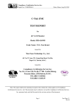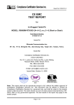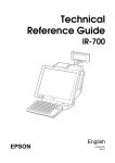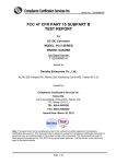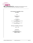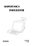
1
Report No: T100909107-D
FCC 47 CFR PART 15 SUBPART B
TEST REPORT
for
Graphics Card
MODEL: eh1
Test Report Number:
T100909107-D
Issued for
VIA TECHNOLOGIES, INC.
1F., No.533, Chung-Cheng Road, Hsin-Tien, Taipei 231, Taiwan
Issued By:
Compliance Certification Services Inc.
Linkuo Laboratory
No. 81-1, Lane 210, Pa-De 2nd Rd., Luchu Hsiang,
Taoyuan Shien, (338), Taiwan, R.O.C.
TEL: 886-3-324-0332
FAX: 886-3-324-5235
E-Mail: [email protected]
Issued Date: September 27, 2010
Note: This report shall not be reproduced except in full, without the written approval of
Compliance Certification Services Inc. This document may be altered or revised by
Compliance Certification Services Inc. personnel only, and shall be noted in the revision
section of the document. The client should not use it to claim product endorsement by TAF,
A2LA, NIST or any government agencies. The test results in the report only apply to the
tested sample.
Page 1 / 25
Report No: T100909107-D
Revision History
Rev.
00
Issue
Date
September 27, 2010
Revisions
Initial Issue
Effect
Page
ALL
Revised By
Celine Chou
Page 2
This report shall not be reproduced except in full, without the written approval of Compliance Certification Services.
Report No: T100909107-D
TABLE OF CONTENTS
1
2
3
3.1.
3.2.
4
4.1.
4.2.
5
5.1.
5.2.
5.3.
6
6.1.
6.2.
6.3.
6.4.
6.5.
6.6.
7
7.1.
7.2.
7.3.
7.4.
7.5.
7.6.
8
TEST RESULT CERTIFICATION ........................................................................... 4
EUT DESCRIPTION................................................................................................ 5
TEST METHODOLOGY.......................................................................................... 6
DECISION OF FINAL TEST MODE ........................................................................ 6
EUT SYSTEM OPERATION ................................................................................... 6
SETUP OF EQUIPMENT UNDER TEST ................................................................ 7
DESCRIPTION OF SUPPORT UNITS.................................................................... 7
CONFIGURATION OF SYSTEM UNDER TEST..................................................... 7
FACILITIES AND ACCREDITATIONS ................................................................... 8
FACILITIES ............................................................................................................. 8
ACCREDITATIONS................................................................................................. 8
MEASUREMENT UNCERTAINTY.......................................................................... 9
CONDUCTED EMISSION MEASUREMENT........................................................ 10
LIMITS OF CONDUCTED EMISSION MEASUREMENT...................................... 10
TEST INSTRUMENTS .......................................................................................... 10
TEST PROCEDURES........................................................................................... 11
TEST SETUP ........................................................................................................ 12
DATA SAMPLE: .................................................................................................... 12
TEST RESULTS ................................................................................................... 13
RADIATED EMISSION MEASUREMENT ............................................................ 15
LIMITS OF RADIATED EMISSION MEASUREMENT .......................................... 15
TEST INSTRUMENTS .......................................................................................... 16
TEST PROCEDURES........................................................................................... 17
TEST SETUP ........................................................................................................ 18
DATA SAMPLE: .................................................................................................... 19
TEST RESULTS ................................................................................................... 20
PHOTOGRAPHS OF THE TEST CONFIGURATION........................................... 24
Page 3
This report shall not be reproduced except in full, without the written approval of Compliance Certification Services.
Report No: T100909107-D
1 TEST RESULT CERTIFICATION
Product:
Graphics Card
Model:
eh1
Brand:
VIA
Applicant:
VIA TECHNOLOGIES, INC.
1F., No.533, Chung-Cheng Road, Hsin-Tien, Taipei 231, Taiwan
Manufacturer:
VIA TECHNOLOGIES, INC.
1F., No.533, Chung-Cheng Road, Hsin-Tien, Taipei 231, Taiwan
Tested:
Test Voltage:
September 16 ~ 21, 2010
100VAC, 60Hz
Standard
FCC 47 CFR Part 15 Subpart B
(July 10, 2008),
ICES-003 Issue 4
ANSI C63.4-2003
EMISSION
Item
Result
Remarks
Conducted (Main Port)
PASS
Meet Class B limit
Radiated
PASS
Meet Class B limit
Note: 1. The statements of test result on the above are decided by the request of test standard only;
the measurement uncertainties are not factored into this compliance determination.
2. The information of measurement uncertainty is available upon the customer’s request.
Deviation from Applicable Standard
None
The above equipment has been tested by Compliance Certification Services Inc., and found
compliance with the requirements set forth in the technical standards mentioned above. The
results of testing in this report apply only to the product/system, which was tested. Other
similar equipment will not necessarily produce the same results due to production tolerance
and measurement uncertainties.
Approved by:
Reviewed by:
Ethan Huang
Section Manager
Stan Lin
Supervisor
Page 4
This report shall not be reproduced except in full, without the written approval of Compliance Certification Services.
Report No: T100909107-D
2 EUT DESCRIPTION
Product
Graphics Card
Brand Name
VIA
Model
eh1
Applicant
VIA TECHNOLOGIES, INC.
Serial Number
T100909107
Received Date
September 9, 2010
EUT Power Rating
Powered by PC
PC Configuration
Power Supply Manufacturer
Sea Soinc
Power Supply Power Rating
I/P: 100-240VAC, 50/60Hz, 9A
Model
SS-500HT Active PFC F3
O/P: 3.3VDC, 30A; -5VDC, 30A; -12V1, 17A; +12V2, 16A;
12V, 0.8A; +5Vsb, 2A
Memory Capacity
3GB
CPU Manufacturer
VIA
Model
1.60GHz
HDD Manufacturer
Samsung
Model
SP1213C (111GB)
LAN Card Manufacturer
On Board
VGA Card Manufacturer
On Board
Sound Card Manufacturer
On Board
I/O PORT
I/O PORT TYPES
Q’TY
TESTED WITH
1. DVI Port
1
1
2. HDMI Port
1
1
Page 5
This report shall not be reproduced except in full, without the written approval of Compliance Certification Services.
Report No: T100909107-D
3 TEST METHODOLOGY
3.1. DECISION OF FINAL TEST MODE
1. The following test mode(s) were scanned during the preliminary test:
Pre-Test Mode
Mode 1: DVI 1920 x 1200 Resolution, 60Hz
Mode 2: HDMI 1920 x 1200 Resolution, 60Hz
Mode 3: DVI 1920 x 1200 Resolution, 60Hz + 1920 x 1200 Resolution, 60Hz
Mode 4: DVI 1440 x 900 Resolution, 60Hz + 1920 x 1200 Resolution, 60Hz
Mode 5: DVI 1024 x 768 Resolution, 60Hz + 1920 x 1200 Resolution, 60Hz
Mode 6: DVI 800 x 600 Resolution, 60Hz + 1920 x 1200 Resolution, 60Hz
2. After the preliminary scan, the following test mode was found to produce the highest
emission level.
Final Test Mode
Emission
Conducted
Emission
Mode 3
Radiated
Emission
Mode 3
Then, the above highest emission mode of the configuration of the EUT and cable
was chosen for all final test items.
3.2. EUT SYSTEM OPERATION
1 Install EUT into the Personal Computer and simulators as shown on 4.2.
2 Turn on the power of all equipment.
3 Personal Computer reads data from disk.
4 EMC Test Run test program, and run "H" pattern.
5
Personal Computer sends “H” pattern to printer, the printer will print “H” pattern on
paper.
6 The H pattern will be shown on the screen of monitor through the EUT.
7 Personal Computer reads and writes data into and from modem.
8 Repeat the above procedure (4) to (7).
Note: Test program is self-repeating throughout the test.
Page 6
This report shall not be reproduced except in full, without the written approval of Compliance Certification Services.
Report No: T100909107-D
4 SETUP OF EQUIPMENT UNDER TEST
4.1. DESCRIPTION OF SUPPORT UNITS
The EUT has been tested as an independent unit together with other necessary accessories or support units.
The following support units or accessories were used to form a representative test configuration during the
tests.
No.
Equipment
Model No.
Serial No.
FCC ID
Trade Name
Data Cable
Power Cord
1
LCD Monitor
2408WFB
CN-0G293H-7426187C-0LVS-A00
FCC DoC
DELL
D-SUB Cable:
Shielded, 1.8m
with two cores
2
LCD Monitor
2408WFB
CN-0G293H-74261874-2CWS
FCC DoC
DELL
HDMI Cable:
Shielded, 1.8m
3
Modem
DM-1414
304012264
IFAXDM1414
ACEEX
4
PS/2 Keyboard
Y-SJ17
SY528UK
FCC DoC
Logitech
Unshielded, 1.8m
N/A
5
PS/2 Mouse
M-S34
HCA25200078
DZL211029
Logitech
Unshielded, 1.8m
N/A
Unshielded, 1.8m
Unshielded, 1.8m
Unshielded, 1.8m Unshielded, 1.8m
Note: Grounding was established in accordance with the manufacturer’s requirements and conditions for
the intended use.
4.2. CONFIGURATION OF SYSTEM UNDER TEST
1. LCD Monitor
2. LCD Monitor
3. Modem
4. PS/2 Keyboard
5. PS/2 Mouse
---
DVI
3
HDMI
Graphics
Card
(EUT)
1
2
PC
4
5
Test table
Page 7
This report shall not be reproduced except in full, without the written approval of Compliance Certification Services.
Report No: T100909107-D
5 FACILITIES AND ACCREDITATIONS
5.1. FACILITIES
All measurement facilities used to collect the measurement data are located at
No. 81-1, Lane 210, Pa-De 2nd Rd., Luchu Hsiang, Taoyuan Shien, Taiwan.
The sites are constructed in conformance with the requirements of ANSI C63.4 and
CISPR 22. All receiving equipment conforms to CISPR 16-1-1, CISPR 16-1-2, CISPR
16-1-3, CISPR 16-1-4, CISPR 16-1-5 and CISPR 16-2-3.
5.2. ACCREDITATIONS
Our laboratories are accredited and approved by the following approval agencies
according to ISO/IEC 17025.
Taiwan
USA
TAF
A2LA
The measuring facility of laboratories has been authorized or registered by the following
approval agencies.
Industry Canada
Canada
Nemko
Norway
VCCI
Japan
BSMI
Taiwan
FCC
USA
Copies of granted accreditation certificates are available for downloading from our web
site, http:///www.ccsrf.com
Page 8
This report shall not be reproduced except in full, without the written approval of Compliance Certification Services.
Report No: T100909107-D
5.3. MEASUREMENT UNCERTAINTY
Where relevant, the following measurement uncertainty levels have been estimated for
tests performed on the EUT as specified in CISPR 16-4-2:
Measurement
Frequency
Conducted emissions
9kHz~30MHz
Uncertainty
±2.0518
30~200MHz
±3.8856
200~1000MHz
±3.8721
Radiated emissions
This uncertainty represents an expanded uncertainty expressed at approximately the 95%
confidence level using a coverage factor of k=2.
Consistent with industry standard (e.g. CISPR 22: 2006, clause 11, Measurement Uncertainty)
determining compliance with the limits shall be base on the results of the compliance
measurement. Consequently the measure emissions being less than the maximum allowed
emission result in this be a compliant test or passing test.
The acceptable measurement uncertainty value without requiring revision of the compliance
statement is base on conducted and radiated emissions being less than UCISPR which is 3.6dB
and 5.2dB respectively. CCS values (called ULab in CISPR 16-4-2) is less than UCISPR as shown
in the table above. Therefore, MU need not be considered for compliance.
Page 9
This report shall not be reproduced except in full, without the written approval of Compliance Certification Services.
Report No: T100909107-D
6 CONDUCTED EMISSION MEASUREMENT
6.1. LIMITS OF CONDUCTED EMISSION MEASUREMENT
FREQUENCY (MHz)
Class A (dBuV)
Class B (dBuV)
Quasi-peak
Average
Quasi-peak
Average
0.15 - 0.5
79
66
66 - 56
56 - 46
0.50 - 5.0
73
60
56
46
5.0 - 30.0
73
60
60
50
NOTE:
(1) The lower limit shall apply at the transition frequencies.
(2) The limit decreases in line with the logarithm of the frequency in the range 0.15 to 0.50 MHz.
(3) All emanations from a class A/B digital device or system, including any network of conductors and
apparatus connected thereto, shall not exceed the level of field strengths specified above.
6.2. TEST INSTRUMENTS
Conducted Emission Room # 4
Name of Equipment
Manufacturer
Model
Serial Number
Calibration Due
EMI Test Receiver
R&S
ESCI
100782
06/10/2011
LISN
R&S
ENV216
100066
03/31/2011
LISN
R&S
ENV 4200
830326/016
04/27/2011
Test S/W
EZ-EMC
NOTE: 1. The calibration interval of the above test instruments is 12 months and the calibrations are
traceable to NML/ROC and NIST/USA.
2. N.C.R = No Calibration Request.
Page 10
This report shall not be reproduced except in full, without the written approval of Compliance Certification Services.
Report No: T100909107-D
6.3. TEST PROCEDURES (please refer to measurement standard or CCS SOP PA-031)
Procedure of Preliminary Test
The EUT and support equipment, if needed, were set up as per the test
configuration to simulate typical usage per the user’s manual. When the EUT is a
tabletop system, a wooden table with a height of 0.8 meters is used and is placed on
the ground plane as per ANSI C63.4 (see Test Facility for the dimensions of the
ground plane used). When the EUT is a floor standing equipment, it is placed on the
ground plane, which has a 12 mm non-conductive covering to insulate the EUT from
the ground plane.
All I/O cables were positioned to simulate typical actual usage as per ANSI C63.4.
The test equipment EUT installed by AC main power, through a Line Impedance
Stabilization Network (LISN), which was supplied power source and was grounded to
the ground plane.
All support equipment power by from a second LISN.
The test program of the EUT was started. Emissions were measured on each
current carrying line of the EUT using an EMI Test Receiver connected to the LISN
powering the EUT.
The Receiver scanned from 150kHz to 30MHz for emissions in each of the test
modes.
During the above scans, the emissions were maximized by cable manipulation.
The test mode(s) described in Item 3.1 were scanned during the preliminary test.
After the preliminary scan, we found the test mode described in Item 3.1 producing
the highest emission level.
The worst configuration of EUT and cable of the above highest emission level were
recorded for reference of the final test.
Procedure of Final Test
EUT and support equipment were set up on the test bench as per the configuration
with highest emission level in the preliminary test.
A scan was taken on both power lines, Line 1 and Line 2, recording at least the six
highest emissions. Emission frequency and amplitude were recorded into a computer
in which correction factors were used to calculate the emission level and compare
reading to the applicable limit.
The test data of the worst-case condition(s) was recorded.
Page 11
This report shall not be reproduced except in full, without the written approval of Compliance Certification Services.
Report No: T100909107-D
6.4. TEST SETUP
Vert. reference plane
EMI receiver
40cm
EUT
80cm
LISN
Reference ground plane
For the actual test configuration, please refer to the related item – Photographs of
the Test Configuration.
6.5. DATA SAMPLE:
Frequency
(MHz)
QuasiPeak
reading
(dBuV)
Average
reading
(dBuV)
Correctrion
factor
(dB)
QuasiPeak
result
(dBuV)
Average
result
(dBuV)
QuasiPeak.
limit
(dBuV)
Average
limit
(dBuV)
QuasiPeak
margin
(dB)
Average
margin
(dB)
Remark
x.xx
43.95
33.00
10.00
53.95
43.00
56.00
46.00
-2.05
-3.00
Pass
Frequency (MHz)
Reading (dBuV)
Correction Factor (dB)
Result (dBuV)
Limit (dBuV)
Margin (dB)
= Emission frequency in MHz
= Uncorrected Analyzer/Receiver reading + Insertion loss of LISN, if it > 0.5 dB
= LISN Factor + Cable Loss
= Raw reading converted to dBuV and CF added
= Limit stated in standard
= Result (dBuV) – Limit (dBuV)
Page 12
This report shall not be reproduced except in full, without the written approval of Compliance Certification Services.
Report No: T100909107-D
6.6. TEST RESULTS
CCS Conduction Test 4
Model No.
eh1
6dB Bandwidth
9 kHz
Environmental
Conditions
25oC, 57% RH
Test Mode
Mode 3
Tested By
Juicheng Su
Line
L1
NO. Frequency
QuasiPeak Average Correction QuasiPeak Average QuasiPeak Average QuasiPeak Average
Remark
reading
reading
factor
result
result
limit
limit
margin
margin
(MHz)
(dBuV)
(dBuV)
(dB)
(dBuV)
(dBuV)
(dBuV)
(dBuV)
(dB)
(dB)
(Pass/Fail)
1
0.1510
20.40
12.56
9.65
30.05
22.21
65.94
55.94
-35.89
-33.73
Pass
2
0.2066
15.82
11.33
9.65
25.47
20.98
63.34
53.34
-37.87
-32.36
Pass
3*
0.2668
22.89
19.38
9.65
32.54
29.03
61.21
51.22
-28.67
-22.19
Pass
4
0.4000
14.66
12.45
9.65
24.31
22.10
57.85
47.85
-33.54
-25.75
Pass
5
0.4688
14.40
12.76
9.58
23.98
22.34
56.53
46.54
-32.55
-24.20
Pass
6
2.8040
16.68
10.43
9.67
26.35
20.10
56.00
46.00
-29.65
-25.90
Pass
REMARKS: L1 = Line One (Live Line)
Page 13
This report shall not be reproduced except in full, without the written approval of Compliance Certification Services.
Report No: T100909107-D
CCS Conduction Test 4
Model No.
eh1
6dB Bandwidth
9 kHz
Environmental
Conditions
25oC, 57% RH
Test Mode
Mode 3
Tested By
Juicheng Su
Line
L2
NO. Frequency
QuasiPeak Average Correction QuasiPeak Average QuasiPeak Average QuasiPeak Average
Remark
reading
reading
factor
result
result
limit
limit
margin
margin
(MHz)
(dBuV)
(dBuV)
(dB)
(dBuV)
(dBuV)
(dBuV)
(dBuV)
(dB)
(dB)
(Pass/Fail)
1
0.1509
20.92
13.38
9.66
30.58
23.04
65.94
55.95
-35.36
-32.91
Pass
2
0.1748
15.53
10.81
9.66
25.19
20.47
64.72
54.73
-39.53
-34.26
Pass
3
0.2017
20.85
13.91
9.66
30.51
23.57
63.54
53.54
-33.03
-29.97
Pass
4
0.2686
21.06
18.67
9.66
30.72
28.33
61.16
51.16
-30.44
-22.83
Pass
5*
0.4013
18.19
16.12
9.66
27.85
25.78
57.83
47.83
-29.98
-22.05
Pass
6
2.8040
16.41
11.15
9.69
26.10
20.84
56.00
46.00
-29.90
-25.16
Pass
REMARKS: L2 = Line Two (Neutral Line)
Page 14
This report shall not be reproduced except in full, without the written approval of Compliance Certification Services.
Report No: T100909107-D
7
RADIATED EMISSION MEASUREMENT
7.1. LIMITS OF RADIATED EMISSION MEASUREMENT
FREQUENCY (MHz)
dBuV/m (At 10m)
Class A
Class B
30 ~ 230
40
30
230 ~ 1000
47
37
Frequency
(MHZ)
Class A (dBuV/m) (At 3m)
Class B (dBuV/m) (At 3m)
Average
Peak
Average
Peak
60
80
54
74
Above 1000
NOTE: (1) The lower limit shall apply at the transition frequencies.
(2) Emission level (dBuV/m) = 20 log Emission level (uV/m).
According to FCC Part 15.33 (b), for an unintentional radiator, including a digital device, the spectrum shall
be investigated from the lowest radio frequency signal generated or used in the device, without going below
the lowest frequency for which a radiated emission limit is specified, up to the frequency shown in the
following table:
Highest frequency generated or used in the device
Upper frequency of measurement range
or in which the device operated or tunes (MHz)
(MHz)
Below 1.75
30
1.75-108
1000
108-500
2000
500-1000
5000
th
5 harmonic of the highest frequency or 40GHz,
whichever is lower
Above 1000
Page 15
This report shall not be reproduced except in full, without the written approval of Compliance Certification Services.
Report No: T100909107-D
7.2. TEST INSTRUMENTS
Open Area Test Site # 1
Name of Equipment
Manufacturer
Model
Serial Number
Calibration Due
Spectrum Analyzer
ADVANTEST
R3261C
81720301
N.C.R
EMI Test Receiver
R&S
ESVS20
838804/004
03/28/2011
Pre-Amplifier
HP
8447D
2944A09173
04/13/2011
Bilog Antenna
TESEQ
CBL 6112D
23189
06/18/2011
Turn Table
CCS
CC-T-1F
N/A
N.C.R
Antenna Tower
CCS
CC-A-1F
N/A
N.C.R
Controller
CCS
CC-C-1F
N/A
N.C.R
RF Switch
Anritsu
MP59B
M54367
N.C.R
Site NSA
CCS
N/A
N/A
01/16/2011
Test S/W
LabVIEW 6.1 (CCS OATS EMI SW V2.7)
3 Meter Chamber
Name of Equipment Manufacturer
Model
Serial Number Calibration Due
Spectrum Analyzer
Agilent
E4446A
MY48250064
11/05/2010
Pre-Amplifier
HP
8449B
3008A00965
04/17/2011
Pre-Amplifier
MITEQ
AMF-6F-260400-40-8P
985646
05/23/2011
Horn Antenna
EMCO
3115
9602-4659
05/09/2011
Horn Antenna
EMCO
3116
00026370
10/13/2010
Low Loss Cable
Huber+Suhner
104PEA
24815/4PEA
08/13/2011
Low Loss Cable
Huber+Suhner
104PEA
30956/4PEA
04/17/2011
Site VSWR
SIDT EUROPE
9x6x6
N/A
02/26/2011
Turn Table
CCS
CC-T-1F
N/A
N.C.R
Antenna Tower
CCS
CC-A-1F
N/A
N.C.R
Controller
CCS
CC-C-1F
N/A
N.C.R
Test S/W
EZ-EMC
NOTE: 1. The calibration interval of the above test instruments is 12 months and the calibrations are
traceable to NML/ROC and NIST/USA.
2. N.C.R = No Calibration Request.
Page 16
This report shall not be reproduced except in full, without the written approval of Compliance Certification Services.
Report No: T100909107-D
7.3. TEST PROCEDURES (please refer to measurement standard or CCS SOP PA-031)
Procedure of Preliminary Test
The equipment was set up as per the test configuration to simulate typical usage
per the user’s manual. When the EUT is a tabletop system, a wooden turntable with a
height of 0.8 meters is used which is placed on the ground plane. When the EUT is a
floor standing equipment, it is placed on the ground plane which has a 3-12 mm
non-conductive covering to insulate the EUT from the ground plane.
Support equipment, if needed, was placed as per ANSI C63.4.
All I/O cables were positioned to simulate typical usage as per ANSI C63.4.
The EUT received AC power source from the outlet socket under the turntable. All
support equipment power received from another socket under the turntable.
The antenna was placed at 3 or 10 meter away from the EUT as stated in ANSI
C63.4. The antenna connected to the Spectrum Analyzer via a cable and at times a
pre-amplifier would be used.
The Analyzer / Receiver quickly scanned from 30MHz to 40GHz. The EUT test
program was started. Emissions were scanned and measured rotating the EUT to
360 degrees and positioning the antenna 1 to 4 meters above the ground plane, in
both the vertical and the horizontal polarization, to maximize the emission reading
level.
The test mode(s) described in Item 3.1 were scanned during the preliminary test:
After the preliminary scan, we found the test mode described in Item 3.1 producing
the highest emission level.
The worst configuration of EUT and cable of the above highest emission level were
recorded for reference of the final test.
Procedure of Final Test
EUT and support equipment were set up on the turntable as per the configuration
with highest emission level in the preliminary test.
The Analyzer / Receiver scanned from 30MHz to 40GHz. Emissions were scanned
and measured rotating the EUT to 360 degrees, varying cable placement and
positioning the antenna 1 or 1 to 4 meters above the ground plane, in both the vertical
and the horizontal polarization, to maximize the emission reading level.
Recording at least the six highest emissions. Emission frequency, amplitude,
antenna position, polarization and turntable position were recorded into a computer in
which correction factors were used to calculate the emission level and compare
reading to the applicable limit and only Q.P. reading is presented.
The test data of the worst-case condition(s) was recorded.
Page 17
This report shall not be reproduced except in full, without the written approval of Compliance Certification Services.
Report No: T100909107-D
7.4. TEST SETUP
Below 1GHz
Test table &
Turntable
1 or 1m ~ 4m
Boundary of
EUT
Coaxial
Cable
Power
Cable
0.8 m
10 m
Filter
Ground Plane
To Power
EMI
Receiver
Above 1GHz
Antenna
tower
Horn
antenna
3m
EUT
4m
Spectrum
analyzer
Turntable
0.8m
1m
Pre-amp
For the actual test configuration, please refer to the related item – Photographs of
the Test Configuration.
Page 18
This report shall not be reproduced except in full, without the written approval of Compliance Certification Services.
Report No: T100909107-D
7.5. DATA SAMPLE:
Below 1GHz
Frequency Reading
(MHz)
(dBuV)
xx.xx
16.49
Correction
Factor
(dB/m)
Result
(dBuV/m)
Limit
(dBuV/m)
Margin
(dB)
Degree
(。)
Height
(cm)
Remark
9.86
26.35
30.00
-3.65
116.00
101.00
QP
Above 1GHz
Frequency
MHz
Corr.
Factor
(dB/m)
xxxx.xxx
-4.35
Reading
Result
Limit
Margin
Average
Peak
Average
Peak
Average
Peak
Average
(dBuV/m) (dBuV/m) (dBuV/m) (dBuV/m) (dBuV/m) (dBuV/m)
(dB)
49.81
Frequency (MHz)
Reading (dBuV)
Correction Factor (dB/m)
Result (dBuV/m)
Limit (dBuV/m)
Margin (dB)
Q.P.
58.74
45.46
54.39
54.00
74.00
-8.54
Peak
(dB)
-19.61
= Emission frequency in MHz
= Uncorrected Analyzer / Receiver reading
= Antenna factor + Cable loss – Amplifier gain
= Reading (dBuV) + Corr. Factor (dB/m)
= Limit stated in standard
= Result (dBuV/m) – Limit (dBuV/m)
= Quasi-Peak
Page 19
This report shall not be reproduced except in full, without the written approval of Compliance Certification Services.
Report No: T100909107-D
7.6. TEST RESULTS
Below 1GHz
Model No.
eh1
Test Mode
Mode 3
Environmental
Conditions
25oC, 56% RH
6dB Bandwidth
120 kHz
Antenna Pole
Vertical
Antenna Distance 10m
Detector Function: Quasi-peak.
No.
Frequency
Reading
Result
(MHz)
(dBuV)
1
64.24
42.42
-18.42
24.00
2
74.08
44.61
-17.41
3
117.28
37.69
4
153.96
5
Limit
Ming Wu
Margin
Degree
Height
(dB)
(°)
(cm)
30.00
-6.00
0.00
100.00
QP
27.20
30.00
-2.80
79.40
100.00
QP
-11.29
26.40
30.00
-3.60
66.00
100.00
QP
40.15
-12.90
27.25
30.00
-2.75
348.80
100.00
QP
185.86
36.56
-13.56
23.00
30.00
-7.00
353.50
100.00
QP
6
233.80
40.75
-10.95
29.80
37.00
-7.20
0.00
400.00
QP
7
462.20
37.34
-2.94
34.40
37.00
-2.60
312.10
166.00
QP
8
616.00
33.59
0.36
33.95
37.00
-3.05
91.30
120.10
QP
9
770.20
32.28
2.52
34.80
37.00
-2.20
232.30
100.00
QP
REMARKS:
Correction
Tested By
Factor(dB/m) (dBuV/m) (dBuV/m)
Remark
The other emission levels were very low against the limit.
Page 20
This report shall not be reproduced except in full, without the written approval of Compliance Certification Services.
Report No: T100909107-D
Model No.
eh1
Test Mode
Mode 3
Environmental
Conditions
25oC, 56% RH
6dB Bandwidth
120 kHz
Antenna Pole
Horizontal
Antenna Distance 10m
Detector Function: Quasi-peak.
No.
Frequency
Reading
Result
(MHz)
(dBuV)
1
72.52
39.36
-17.67
21.69
2
124.20
32.75
-11.15
3
154.07
33.53
4
184.29
5
Limit
Ming Wu
Margin
Degree
Height
(dB)
(°)
(cm)
30.00
-8.31
150.10
400.00
QP
21.60
30.00
-8.40
147.20
400.00
QP
-12.91
20.62
30.00
-9.38
128.00
400.00
QP
36.63
-13.63
23.00
30.00
-7.00
331.60
400.00
QP
233.60
38.18
-10.98
27.20
37.00
-9.80
225.60
400.00
QP
6
462.16
35.14
-2.94
32.20
37.00
-4.80
353.90
165.80
QP
7
616.90
30.84
0.36
31.20
37.00
-5.80
29.00
120.70
QP
8
770.20
32.08
2.52
34.60
37.00
-2.40
239.20
100.00
QP
REMARKS:
Correction
Tested By
Factor(dB/m) (dBuV/m) (dBuV/m)
Remark
The other emission levels were very low against the limit.
Page 21
This report shall not be reproduced except in full, without the written approval of Compliance Certification Services.
Report No: T100909107-D
Above 1GHz
Model No.
eh1
Test Mode
Mode 3
Environmental
Conditions
18oC, 60% RH
6dB Bandwidth
1 MHz
Antenna Pole
Vertical
Antenna Distance
3m
Tested By
Han Chaic
Detector Function: Peak/Average
Frequency
Corr.
Reading
Factor
MHz
Average
Peak
Result
Average
Limit
Peak
Average
Margin
Peak
(dBuV/m) (dBuV/m) (dBuV/m) (dBuV/m) (dBuV/m) (dBuV/m) (dBuV/m)
Degree
Height
Average
Peak
(dB)
(dB)
(°)
(cm)
1640.000
-5.89
--
51.92
--
46.03
--
74.00
--
-27.97
244
100
2110.000
-3.27
--
49.23
--
45.96
--
74.00
--
-28.04
178
100
2240.000
-2.83
--
49.04
--
46.21
--
74.00
--
-27.79
360
100
2590.000
-1.49
--
48.93
--
47.44
--
74.00
--
-26.56
256
100
3060.000
0.64
--
47.01
--
47.65
--
74.00
--
-26.35
133
100
3530.000
2.22
--
45.49
--
47.71
--
74.00
--
-26.29
224
100
REMARKS:
1. The other emission levels were very low against the limit.
2. “--”, means the average measurement was not performed when the measured peak data
under the limit of average detection.
Page 22
This report shall not be reproduced except in full, without the written approval of Compliance Certification Services.
Report No: T100909107-D
Model No.
eh1
Test Mode
Mode 3
Environmental
Conditions
18oC, 60% RH
6dB Bandwidth
1 MHz
Antenna Pole
Horizontal
Antenna Distance
3m
Tested By
Han Chaic
Detector Function: Peak/Average
Frequency
Corr.
Reading
Factor
MHz
Average
Peak
Result
Average
Limit
Peak
Average
Margin
Peak
(dBuV/m) (dBuV/m) (dBuV/m) (dBuV/m) (dBuV/m) (dBuV/m) (dBuV/m)
Degree
Height
Average
Peak
(dB)
(dB)
(°)
(cm)
1360.000
-7.56
--
51.57
--
44.01
--
74.00
--
-29.99
322
100
1470.000
-6.92
--
49.75
--
42.83
--
74.00
--
-31.17
199
100
1582.001
-6.24
--
48.91
--
42.67
--
74.00
--
-31.33
178
100
1920.000
-4.15
--
49.72
--
45.57
--
74.00
--
-28.43
334
100
2150.000
-3.13
--
47.42
--
44.29
--
74.00
--
-29.71
166
100
2820.000
-0.40
--
47.04
--
46.64
--
74.00
--
-27.36
244
100
REMARKS:
1. The other emission levels were very low against the limit.
2. “--”, means the average measurement was not performed when the measured peak data
under the limit of average detection.
Page 23
This report shall not be reproduced except in full, without the written approval of Compliance Certification Services.
Report No: T100909107-D
8 PHOTOGRAPHS OF THE TEST CONFIGURATION
CONDUCTED EMISSION TEST
Page 24
This report shall not be reproduced except in full, without the written approval of Compliance Certification Services.
Report No: T100909107-D
RADIATED EMISSION TEST
Page 25
This report shall not be reproduced except in full, without the written approval of Compliance Certification Services.