1
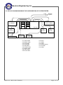
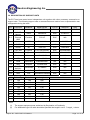
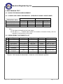
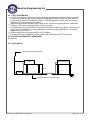
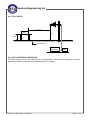
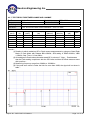
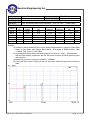
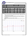
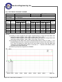
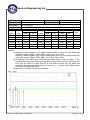
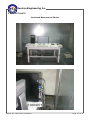
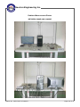
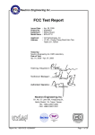
RV-0000000
Neutron Engineering Inc.
FCC Test Report
Apr. 29, 2010
E1004071
Mother Board
EPIA-M830
Issued Date
Project No.
Equipment
Model Name
:
:
:
:
Applicant
Address
: VIA Technologies, Inc.
: 8F, 535, Chung-Cheng Road Hsin-Tien,
Taipei 231, Taiwan
Tested by: Neutron Engineering Inc. EMC Laboratory
Date of Receipt: Apr. 20, 2010
Date of Test: Apr. 20, 2010 ~ Apr. 23, 2010
Te s t i n g E n g i n e e r :
(Peter Li)
Technical Manager :
(Jeff Yang)
Authorized Signatory :
(Andy Chiu)
Neutron Engineering Inc.
B1, No. 37, Lane 365, YangGuang St.,
NeiHu District 114, Taipei, Taiwan.
TEL: +886-2-2657-3299
FAX: +886-2-2657-3331
Report No.: NEI-FCCE-1-E1004071
Page 1 of 31
Neutron Engineering Inc.
RV-0000000
Declaration
Neutron represents to the client that testing is done in accordance with standard procedures as applicable
and that test instruments used has been calibrated with the standards traceable to National Measurement
Laboratory (NML) of R.O.C., or National Institute of Standards and Technology (NIST) of U.S.A.
Neutron's reports apply only to the specific samples tested under conditions. It is manufacture’s
responsibility to ensure that additional production units of this model are manufactured with the identical
electrical and mechanical components. Neutron shall have no liability for any declarations, inferences or
generalizations drawn by the client or others from Neutron issued reports.
Neutron’s reports must not be used by the client to claim product endorsement by the authorities or any
agency of the Government.
This report is the confidential property of the client. As a mutual protection to the clients, the public and
Neutron-self, extracts from the test report shall not be reproduced except in full with Neutron’s authorized
written approval.
Neutron’s laboratory quality assurance procedures are in compliance with the ISO Guide 17025
requirements, and accredited by the conformity assessment authorities listed in this test report.
Limitation
For the use of the authority's logo is limited unless the Test Standard(s)/Scope(s)/Item(s) mentioned in this
test report is (are) included in the conformity assessment authorities acceptance respective.
Report No.: NEI-FCCE-1-E1004071
Page 2 of 31
RV-0000000
Neutron Engineering Inc.
Table of Contents
Page
1 . CERTIFICATION
4
2 . SUMMARY OF TEST RESULTS
5
2.1 TEST FACILITY
6
2.2 MEASUREMENT UNCERTAINTY
6
3 . GENERAL INFORMATION
7
3.1 GENERAL DESCRIPTION OF EUT
7
3.2 DESCRIPTION OF TEST MODES
8
3.3 BLOCK DIAGRAM SHOWING THE CONFIGURATION OF SYSTEM TESTED
9
3.4 DESCRIPTION OF SUPPORT UNITS
4 . EMC EMISSION TEST
10
11
4.1 CONDUCTED EMISSION MEASUREMENT
4.1.1 POWER LINE CONDUCTED EMISSION
4.1.2 MEASUREMENT INSTRUMENTS LIST
4.1.3 TEST PROCEDURE
4.1.4 DEVIATION FROM TEST STANDARD
4.1.5 TEST SETUP
4.1.6 EUT OPERATING CONDITIONS
4.1.7 TEST RESULTS
11
11
11
12
12
12
13
14
4.2 RADIATED EMISSION MEASUREMENT
4.2.1 LIMITS OF RADIATED EMISSION MEASUREMENT
4.2.2 MEASUREMENT INSTRUMENTS LIST
4.2.3 TEST PROCEDURE
4.2.4 DEVIATION FROM TEST STANDARD
4.2.5 TEST SETUP
4.2.6 EUT OPERATING CONDITIONS
4.2.7 TEST RESULTS-BETWEEN 30MHZ AND 1000MHZ
4.2.8 TEST RESULTS-ABOVE 1000MHZ
16
16
17
17
17
18
18
19
23
5 . EUT TEST PHOTO
Report No.: NEI-FCCE-1-E1004071
27
Page 3 of 31
Neutron Engineering Inc.
RV-0000000
1. CERTIFICATION
Equipment :
Brand Name :
Model Name :
Applicant:
Date of Test :
Sta n d a r d s :
Mother Board
VIA
EPIA-M830
VIA Technologies, Inc.
Apr. 20, 2010 ~ Apr. 23, 2010
FCC Part 15, Subpart B Class B
CISPR 22: 2005 +A1: 2005 Class B
ICES-003: 2004 Class B
ANSI C63.4 (2003)
The above equipment has been tested and found compliance with the requirement of the relative
standards by Neutron Engineering Inc. EMC Laboratory.
The test data, data evaluation, and equipment configuration contained in our test report (Ref No.
NEI-FCCE-1-E1004071) were obtained utilizing the test procedures, test instruments, test sites
that has been accredited by the Authority of NVLAP and TAF according to the ISO-17025 quality
assessment standard and technical standard(s).
Report No.: NEI-FCCE-1-E1004071
Page 4 of 31
RV-0000000
Neutron Engineering Inc.
2. SUMMARY OF TEST RESULTS
Test procedures according to the technical standards:
Emission
Standard
Test Item
Limit
Judgment
FCC Part 15, Subpart B
CISPR 22: 2005 +A1: 2005
ICES-003: 2004
Conducted Emission
Class B
PASS
Radiated Emission
Class B
PASS
Remark
NOTE:
(1) ” N/A” denotes test is not applicable in this Test Report.
(2) According to FCC Part 15 Support B 15.32 (a)(1)(i), the EUT(CPU Board) should be
tested under two conditions: Open case & Close case for Radiated test.
And the test data can’t be over 6dB against the limit under the Open case condition.
*Normal test condition is close case.
Report No.: NEI-FCCE-1-E1004071
Page 5 of 31
RV-0000000
Neutron Engineering Inc.
2.1 TEST FACILITY
The test facilities used to collect the test data in this report is C01/OS02/CB08 at the location of
No.132-1, Lane 329, Sec. 2, Palian Road, Shijr City, Taipei, Taiwan & 1F., No. 61, Ln. 77,
Sing-ai Rd., Neihu Dist., Taipei City 114, Taiwan (R.O.C.)
2.2 MEASUREMENT UNCERTAINTY
The reported uncertainty of measurement y ± U,where expended uncertainty U is based on a
standard uncertainty multiplied by a coverage factor of k=2,providing a level of confidence of
approximately 95%。
The measurement instrumentation uncertainty considerations contained in CISPR 16-4-2.
A. Conducted Measurement :
Test Site
C01
Method
ANSI
Measurement Frequency Range
150 KHz ~ 30MHz
U,(dB)
1.94
NOTE
U,(dB)
NOTE
B. Radiated Measurement :
Test Site
Method
OS-01
ANSI
OS-02
ANSI
Measurement Frequency
Range
30MHz ~ 200MHz
30MHz ~ 200MHz
200MHz ~ 1,000MHz
200MHz ~ 1,000MHz
30MHz ~ 200MHz
30MHz ~ 200MHz
200MHz ~ 1,000MHz
200MHz ~ 1,000MHz
Ant.
H/V
V
H
V
H
V
H
V
H
2.86
2.56
2.88
2.98
2.48
2.16
2.50
2.66
Our calculated Measurement Instrumentation Uncertainty is shown in the tables above. These
are our Ulab values in CISPR 16-4-2 terminology.
Since Table 1 of CISPR 16-4-2 has values of measurement instrumentation uncertainty, called
UCISPR, as follows:
Conducted Disturbance (mains port) – 150 kHz – 30 MHz : 3.6 dB
Radiated Disturbance (electric field strength on an open area test site or alternative test
site) – 30 MHz – 1000 MHz : 5.2 dB
It can be seen that our Ulab values are smaller than UCISPR.
Report No.: NEI-FCCE-1-E1004071
Page 6 of 31
Neutron Engineering Inc.
RV-0000000
3. GENERAL INFORMATION
3.1 GENERAL DESCRIPTION OF EUT
Equipment
Mother Board
Brand Name
VIA
Model Name
EPIA-M830
OEM Brand/Model Name N/A
Power Source
N/A
The EUT is a Mother Board.
Based on the application, features, or specification
exhibited in User's Manual, the EUT is considered as an
ITE/Computing Device. More details of EUT technical
specification, please refer to the User's Manual.
Supplied from PC ATX Slot.
Power Rating
Please refer to the User's Manual
Connecting I/O Port(s)
Please refer to the User's Manual
Products Covered
N/A
EUT Modification(s)
N/A
Model Difference
Product Description
Note:
1. For a more detailed features description, please refer to the manufacturer’s specifications
or the User's Manual.
Report No.: NEI-FCCE-1-E1004071
Page 7 of 31
RV-0000000
Neutron Engineering Inc.
3.2 DESCRIPTION OF TEST MODES
To investigate the maximum EMI emission characteristics generates from EUT, the test system
was pre-scanning tested base on the consideration of following EUT operation mode or test
configuration mode which possible have effect on EMI emission level. Each of these EUT
operation mode(s) or test configuration mode(s) mentioned above was evaluated respectively.
Pretest Test Mode
Description
Mode 1
FULL SYSTEM D-SUB 1920*1200/60Hz(CPU 1.3 GHz)
Mode 2
FULL SYSTEM D-SUB 1280*1024/60Hz(CPU 1.3 GHz)
Mode 3
FULL SYSTEM D-SUB 800*600/60Hz(CPU 1.3 GHz)
Mode 4
FULL SYSTEM D-SUB 1920*1200/60Hz(CPU 1.0 GHz)
Mode 5
FULL SYSTEM D-SUB 1280*1024/60Hz(CPU 1.0 GHz)
Mode 6
FULL SYSTEM D-SUB 800*600/60Hz(CPU 1.0 GHz)
For Conducted Test
Final Test Mode
Description
Mode 1
FULL SYSTEM D-SUB 1920*1200/60Hz(CPU 1.3 GHz)
For Radiated Test
Final Test Mode
Description
Mode 1
FULL SYSTEM D-SUB 1920*1200/60Hz(CPU 1.3 GHz)
Report No.: NEI-FCCE-1-E1004071
Page 8 of 31
RV-0000000
Neutron Engineering Inc.
3.3 BLOCK DIAGRAM SHOWING THE CONFIGURATION OF SYSTEM TESTED
Remote
System
C-9
C-1
E-2 Monitor
C-2*2
C-5*6
E-12
E-10
E-13
E-11
E-14
E-15
E-4
Modem*2
C-3
E-7 Keyboard
E-3 2.5" HDD*6
E-5 Case
C-7*2
E-4
Modem*2
C-4
E-8
Mouse
E-6
Printer
C-8*2
E-9
Headset
C-1 D-Sub Cable
C-2 RS232 Cable
C-3 PS/2 Cable
C-4 PS/2 Cable
C-5 USB Cable
C-6 Parallel Cable
C-7 RS232 Cable
C-8 Audio Cable
C-9 RJ-45 Cable
Report No.: NEI-FCCE-1-E1004071
C-6
E-10 CPU
E-11 RAM
E-12 HDD
E-13 Power Supoly
E-14 CD-RW
E-15 HDD
Page 9 of 31
RV-0000000
Neutron Engineering Inc.
3.4 DESCRIPTION OF SUPPORT UNITS
The EUT has been tested as an independent unit together with other necessary accessories or
support units. The following support units or accessories were used to form a representative test
configuration during the tests.
Item
Equipment
E-1 Mother Board
24” LCD
E-2
Monitor
2.5”Mobile
E-3
External
HDD
E-4
Modem
Mfr/Brand
Model/Type No.
FCC ID
Series No.
Note
VIA
EPIA-M830
DOC
N/A
EUT
DELL
2408WFPb
DOC
071863-11
FireWire
F12-UF
DOC
N/A
ACEEX
DM-1414V
DOC
8041708
E-5
CASE
VIA
N/A
N/A
N/A
E-6
Printer
SII
DPU-414
DOC
1045105A
E-7
PS/2 K/B
Logitech
Y-SJ17(ACK260A)
DOC
SYU44664880
E-8
PS/2 Mouse
Logitech
M-SBF69
DOC
HCA44601156
E-9
Headset
i-Acon
HOH-323-BK
N/A
N/A
E-10
CPU
VIA
Nano U3100
N/A
N/A
E-11
RAM
Transcend
2GB/DDR2/667
N/A
N/A
E-12
HDD
Seagate
ST380013AS
DOC
N/A
Seventeam
ST-300BLV
DOC
N/A
ASUS
CRW-4012A
DOC
N/A
WD
WD2500KS-00MJBO
DOC
N/A
E-14
POWER
SUPPLY
CD-RW
E-15
HDD
Item
C-1
Shielded Type
YES
Ferrite Core
YES
Length
1.8M
C-2
YES
NO
1.7M
C-3
YES
NO
1.5M
C-4
YES
NO
1.7M
C-5
YES
NO
1.8M
C-6
YES
NO
1.7M
C-7
YES
NO
1.7M
C-8
NO
NO
1.8M
C-9
NO
NO
10M
E-13
Note
Note:
(1)
(2)
The support equipment was authorized by Declaration of Conformity.
For detachable type I/O cable should be specified the length in cm in『Length』column.
Report No.: NEI-FCCE-1-E1004071
Page 10 of 31
RV-0000000
Neutron Engineering Inc.
4. EMC EMISSION TEST
4.1 CONDUCTED EMISSION MEASUREMENT
4.1.1 POWER LINE CONDUCTED EMISSION (FREQUENCY RANGE 150KHZ-30MHZ)
FREQUENCY (MHz)
Class A (dBuV)
Class B (dBuV)
Quasi-peak
Average
Quasi-peak
Average
0.15 -0.5
79.00
66.00
66 - 56 *
56 - 46 *
0.50 -5.0
73.00
60.00
56.00
46.00
5.0 -30.0
73.00
60.00
60.00
50.00
Note:
(1) The tighter limit applies at the band edges.
(2) The limit of " * " marked band means the limitation decreases linearly with the
logarithm of the frequency in the range.
4.1.2 MEASUREMENT INSTRUMENTS LIST
Item Kind of Equipment
LISN
1
Manufacturer
EMCO
Type No.
3816/2
Serial No.
00042991
Calibrated until
Feb. 07, 2011
2
Test Cable
N/A
SR03_C_01&02
N/A
Aug. 19, 2010
3
Pulse Limiter
Electro-Metrics
EM-7600
112644
Dec. 27, 2010
4
EMI Test Receiver
50Ω BNC TYPE
Terminator
50Ω BNC TYPE
Terminator
LISN
R&S
ESCI
100082
Mar. 16, 2011
N/A
N/A
01
May 25, 2011
N/A
N/A
03
May 25, 2011
EMCO
4825/2
00028234
Jul. 13, 2010
5
6
7
Remark: ” N/A” denotes No Model Name , Serial No. or No Calibration specified.
Report No.: NEI-FCCE-1-E1004071
Page 11 of 31
RV-0000000
Neutron Engineering Inc.
4.1.3 TEST PROCEDURE
a. The EUT was placed 0.8 meters from the horizontal ground plane with EUT being connected
to the power mains through a line impedance stabilization network (LISN). All other support
equipments powered from additional LISN(s). The LISN provide 50 Ohm/ 50uH of coupling
impedance for the measuring instrument.
b. Interconnecting cables that hang closer than 40 cm to the ground plane shall be folded back
and forth in the center forming a bundle 30 to 40 cm long.
c. I/O cables that are not connected to a peripheral shall be bundled in the center. The end of the
cable may be terminated, if required, using the correct terminating impedance. The overall
length shall not exceed 1 m.
d. LISN at least 80 cm from nearest part of EUT chassis.
e. For the actual test configuration, please refer to the related Item –EUT Test Photos.
4.1.4 DEVIATION FROM TEST STANDARD
No deviation
4.1.5 TEST SETUP
Vertical Reference Ground Plane
40 cm
EUT
Test Receiver
80 cm
LISN
Horizontal Reference Ground Plane
Report No.: NEI-FCCE-1-E1004071
Page 12 of 31
Neutron Engineering Inc.
RV-0000000
4.1.6 EUT OPERATING CONDITIONS
The EUT exercise program (EMC.exe) used during radiated and/or conducted emission
measurement was designed to exercise the various system components in a manner similar to a
typical use. The program contained on a PC hard disk and is auto-starting on power-up. Once
loaded, the program sequentially exercises each system component in turn. The sequence used
is:
1. Read (write) from (to) mass storage device (External HDD).
2. Send "H" pattern to video port device (Monitor).
3. Send " H " pattern to parallel port device (Printer).
4. Send " H " pattern to serial port device (Modem).
5. Send/Receive data to/from remote system.
6. Send/Receive audio to/from audio devices.
7. Repeated from 2 to 6 continuously.
As the keyboard and mouse are strictly input devices, no data is transmitted to (from) them during
test. They are, however, continuously scanned for data input activity.
Report No.: NEI-FCCE-1-E1004071
Page 13 of 31
RV-0000000
Neutron Engineering Inc.
4.1.7 TEST RESULTS
E.U.T :
Temperature :
Test Voltage :
Test Mode :
Freq.
(MHz)
0.15
0.20
0.24
0.37
6.20
16.70
Mother Board
Model Name :
EPIA-M830
24°C
Relative Humidity : 51%
AC 120V/60Hz
FULL SYSTEM D-SUB 1920*1200/60Hz(CPU 1.3 GHz)
Terminal
L/N
Line
Line
Line
Line
Line
Line
Measured(dBuV)
QP-Mode AV-Mode
53.90
*
46.97
*
45.21
*
35.71
*
28.88
*
40.36
*
Limits(dBuV)
QP-Mode AV-Mode
65.92
55.92
63.57
53.57
62.06
52.06
58.43
48.43
60.00
50.00
60.00
50.00
Margin
(dB)
-12.02
-16.60
-16.85
-22.72
-31.12
-19.64
Note
(QP)
(QP)
(QP)
(QP)
(QP)
(QP)
Remark
:
(1) Reading in which marked as QP means measurements by using are Quasi-Peak Mode with
Detector BW=9KHz;SPA setting in RBW=10KHz,VBW =10KHz, Swp. Time = 0.2 sec./MHz。
Reading in which marked as AV means measurements by using are Average Mode with
instrument setting in RBW=10KHz,VBW=10KHz, Swp. Time =0.2 sec./MHz。
(2) All readings are QP Mode value unless otherwise stated AVG in column of『Note』
. If the QP
Mode Measured value compliance with the QP Limits and lower than AVG Limits, the EUT
shall be deemed to meet both QP & AVG Limits and then only QP Mode was measured,
but AVG Mode didn‘t perform。In this case, a “ * ” marked in AVG Mode column of
Interference Voltage Measured。
(3) Measuring frequency range from 150KHz to 30MHz。
Report No.: NEI-FCCE-1-E1004071
Page 14 of 31
RV-0000000
Neutron Engineering Inc.
E.U.T :
Temperature :
Test Voltage :
Test Mode :
Freq.
(MHz)
0.15
0.17
0.21
0.24
0.37
16.70
Mother Board
Model Name :
EPIA-M830
24°C
Relative Humidity : 51%
AC 120V/60Hz
FULL SYSTEM D-SUB 1920*1200/60Hz(CPU 1.3 GHz)
Terminal
L/N
Neutral
Neutral
Neutral
Neutral
Neutral
Neutral
Measured(dBuV)
QP-Mode AV-Mode
52.43
*
49.31
*
44.34
*
42.08
*
32.48
*
40.09
*
Limits(dBuV)
QP-Mode AV-Mode
65.92
55.92
65.05
55.05
63.39
53.39
62.21
52.21
58.40
48.40
60.00
50.00
Margin
(dB)
-13.49
-15.74
-19.05
-20.13
-25.92
-19.91
Note
(QP)
(QP)
(QP)
(QP)
(QP)
(QP)
Remark
:
(1) Reading in which marked as QP means measurements by using are Quasi-Peak Mode with
Detector BW=9KHz;SPA setting in RBW=10KHz,VBW =10KHz, Swp. Time = 0.2 sec./MHz。
Reading in which marked as AV means measurements by using are Average Mode with
instrument setting in RBW=10KHz,VBW=10KHz, Swp. Time =0.2 sec./MHz。
(2) All readings are QP Mode value unless otherwise stated AVG in column of『Note』
. If the QP
Mode Measured value compliance with the QP Limits and lower than AVG Limits, the EUT
shall be deemed to meet both QP & AVG Limits and then only QP Mode was measured,
but AVG Mode didn‘t perform。In this case, a “ * ” marked in AVG Mode column of
Interference Voltage Measured。
(3) Measuring frequency range from 150KHz to 30MHz。
Report No.: NEI-FCCE-1-E1004071
Page 15 of 31
RV-0000000
Neutron Engineering Inc.
4.2 RADIATED EMISSION MEASUREMENT
4.2.1 LIMITS OF RADIATED EMISSION MEASUREMENT (BELOW 1000MHZ)
FREQUENCY (MHz)
Class A (at 10m)
Class B (at 10m)
dBuV/m
dBuV/m
40
30
30 – 230
230 – 1000
47
37
Notes:
(1) The limit for radiated test was performed according to as following:
CISPR 22/ FCC PART 15B /ICES-003.
(2) The tighter limit applies at the band edges.
(3) Emission level (dBuV/m)=20log Emission level (uV/m).
LIMITS OF RADIATED EMISSION MEASUREMENT (ABOVE 1000MHZ)
FREQUENCY (MHz)
Class A (dBuV/m) (at 3m)
Above 1000
Class B (dBuV/m) (at 3m)
PEAK
AVERAGE
PEAK
AVERAGE
80
60
74
54
Notes:
(1) The limit for radiated test was performed according to FCC PART 15B.
(2) The tighter limit applies at the band edges.
(3) Emission level (dBuV/m)=20log Emission level (uV/m).
FREQUENCY RANGE OF RADIATED MEASUREMENT (FOR UNINTENTIONAL
RADIATORS)
Highest frequency generated or Upper
frequency of measurement used in the
device or on which the device operates
or tunes (MHz)
Range (MHz)
Below 1.705
30
1.705 – 108
1000
108 – 500
2000
500 – 1000
5000
5 harmonic of the highest frequency or
40 GHz, whichever is lower
Above 1000
Report No.: NEI-FCCE-1-E1004071
th
Page 16 of 31
RV-0000000
Neutron Engineering Inc.
4.2.2 MEASUREMENT INSTRUMENTS LIST
Item Kind of Equipment
1 Log-Bicon Antenna
Manufacturer
Schwarzbeck
Type No.
VULB 9160
Serial No.
3173
Calibrated until
Oct. 15, 2010
2
Pre-Amplifier
Anritsu
MH648A
M98457
Jan. 18, 2011
3
Test Cable
N/A
10M-OS01
N/A
Jun. 18, 2010
4
Test Cable
N/A
OS02
01
Jun. 23, 2010
5
EMI Test Receiver
R&S
ESCI
100082
Mar. 16, 2011
6
System Controller
(OS02)
CT
SC100
N/A
N/A
7
Turn Table
Chance Most
CMTB-1.5
N/A
N/A
8
Schwarzbeck
BBHA 9120 D
9120D-546
May. 19, 2010
Agilent
8449B
3008A01714
Apr. 19, 2011
10
Horn Antenna
Microwave
Pre_amplifier
Microflex Cable
N/A
N/A
1m
May. 20, 2010
11
Microflex Cable
AISI
S104-SMAP-1
10m
Aug. 23, 2010
12
Microflex Cable
N/A
N/A
3m
Aug. 23, 2010
13
Spectrum Analyzer
R&S
FSP-40
100129
Sep. 10, 2010
9
Remark: ” N/A” denotes No Model Name / Serial No. and No Calibration specified.
4.2.3 TEST PROCEDURE
a. The measuring distance of at 10 m shall be used for measurements at frequency up to 1GHz.
For frequencies above 1GHz, any suitable measuring distance may be used.
b. The EUT was placed on the top of a rotating table 0.8 meters above the ground at a 3m or 10
meter open area test site. The table was rotated 360 degrees to determine the position of the
highest radiation.
c. The height of the equipment or of the substitution antenna shall be 0.8 m; the height of the test
antenna shall vary between 1 m to 4 m. Both horizontal and vertical polarizations of the
antenna are set to make the measurement.
d. The initial step in collecting radiated emission data is a spectrum analyzer peak detector mode
pre-scanning the measurement frequency range. Significant peaks are then marked and then
Quasi Peak detector mode re-measured.
e. If the Peak Mode measured value compliance with and lower than Quasi Peak Mode Limit, the
EUT shall be deemed to meet QP Limits and then no additional QP Mode measurement
performed.
f. For the actual test configuration, please refer to the related Item –EUT Test Photos.
4.2.4 DEVIATION FROM TEST STANDARD
No deviation
Report No.: NEI-FCCE-1-E1004071
Page 17 of 31
RV-0000000
Neutron Engineering Inc.
4.2.5 TEST SETUP
3 or 10 m
EUT
1-4 m
80 cm
Ground Plane
Test
Receiver
Amp.
4.2.6 EUT OPERATING CONDITIONS
The EUT tested system was configured as the statements of 4.1.6 Unless otherwise a special
operating condition is specified in the follows during the testing.
Report No.: NEI-FCCE-1-E1004071
Page 18 of 31
RV-0000000
Neutron Engineering Inc.
4.2.7 TEST RESULTS-BETWEEN 30MHZ AND 1000MHZ
E.U.T :
Temperature :
Test Voltage :
Test Mode :
Freq.
(MHz)
120.03
240.01
250.00
480.04
600.14
875.00
Mother Board
Model Name :
EPIA-M830
16°C
Relative Humidity : 86%
AC 120V/60Hz
FULL SYSTEM D-SUB 1920*1200/60Hz(CPU 1.3 GHz)
Ant.
H/V
V
V
V
V
V
V
Reading(RA) Corr.Factor(CF) Measured(FS)
(dBuV)
(dB)
(dBuV/m)
26.43
32.60
-6.17
28.45
34.20
-5.75
34.08
39.55
-5.47
33.04
32.02
1.02
34.62
30.89
3.73
26.80
7.93
34.73
Limits(QP)
(dBuV/m)
30.00
37.00
37.00
37.00
37.00
37.00
Margin
(dB)
- 3.57
- 8.55
- 2.92
- 3.96
- 2.38
-
Note
(QP)
2.27
Remark:
(1) Reading in which marked as QP or Peak means measurements by using are Quasi-Peak
Mode or Peak Mode with Detector BW=120KHz;SPA setting in RBW=120KHz, VBW
=120KHz, Swp. Time = 0.3 sec./MHz。
(2) All readings are Peak unless otherwise stated QP in column of『Note』. Peak denotes
that the Peak reading compliance with the QP Limits and then QP Mode measure-ment
didn‘t perform。
(3) Measuring frequency range from 30MHz to 1000MHz。
(4) If the peak scan value is under the limit for more than 20dB, the signal will not show in
table。
Report No.: NEI-FCCE-1-E1004071
Page 19 of 31
RV-0000000
Neutron Engineering Inc.
E.U.T :
Temperature :
Test Voltage :
Test Mode :
Freq.
(MHz)
240.02
480.05
500.00
720.17
876.00
960.09
Mother Board
Model Name :
EPIA-M830
16°C
Relative Humidity : 86%
AC 120V/60Hz
FULL SYSTEM D-SUB 1920*1200/60Hz(CPU 1.3 GHz)
Ant.
H/V
H
H
H
H
H
H
Reading(RA) Corr.Factor(CF) Measured(FS)
(dBuV)
(dB)
(dBuV/m)
29.85
35.60
-5.75
34.62
33.60
1.02
33.88
32.51
1.37
31.02
25.83
5.19
34.06
26.13
7.93
24.16
9.64
33.80
Limits(QP)
(dBuV/m)
37.00
37.00
37.00
37.00
37.00
37.00
Margin
(dB)
- 7.15
- 2.38
- 3.12
- 5.98
- 2.94
-
Note
(QP)
(QP)
(QP)
3.20
Remark:
(1) Reading in which marked as QP or Peak means measurements by using are Quasi-Peak
Mode or Peak Mode with Detector BW=120KHz;SPA setting in RBW=120KHz, VBW
=120KHz, Swp. Time = 0.3 sec./MHz。
(2) All readings are Peak unless otherwise stated QP in column of『Note』. Peak denotes
that the Peak reading compliance with the QP Limits and then QP Mode measure-ment
didn‘t perform。
(3) Measuring frequency range from 30MHz to 1000MHz。
(4) If the peak scan value is under the limit for more than 20dB, the signal will not show in
table。
Report No.: NEI-FCCE-1-E1004071
Page 20 of 31
RV-0000000
Neutron Engineering Inc.
E.U.T :
Temperature :
Test Voltage :
Test Mode :
Freq.
(MHz)
240.04
250.01
480.01
500.00
720.04
1000.00
Mother Board
Model Name :
EPIA-M830
16°C
Relative Humidity : 86%
AC 120V/60Hz
FULL SYSTEM D-SUB 1920*1200/60Hz(CPU 1.3 GHz)_OPEN CASE
Ant.
H/V
V
V
V
V
V
V
Reading(RA) Corr.Factor(CF) Measured(FS)
(dBuV)
(dB)
(dBuV/m)
31.35
37.10
-5.75
34.30
39.77
-5.47
37.82
36.80
1.02
39.84
38.47
1.37
34.78
29.60
5.18
29.43
10.18
39.61
Limits(QP)
(dBuV/m)
37.00
37.00
37.00
37.00
37.00
37.00
Margin
(dB)
- 5.65
- 2.70
0.82
2.84
- 2.22
Note
(QP)
(QP)
(QP)
2.61
Remark:
(1) Reading in which marked as QP or Peak means measurements by using are Quasi-Peak
Mode or Peak Mode with Detector BW=120KHz;SPA setting in RBW=120KHz, VBW
=120KHz, Swp. Time = 0.3 sec./MHz。
(2) All readings are Peak unless otherwise stated QP in column of『Note』. Peak denotes
that the Peak reading compliance with the QP Limits and then QP Mode measure-ment
didn‘t perform。
(3) Measuring frequency range from 30MHz to 1000MHz。
(4) If the peak scan value is under the limit for more than 20dB, the signal will not show in
table。
Report No.: NEI-FCCE-1-E1004071
Page 21 of 31
RV-0000000
Neutron Engineering Inc.
E.U.T :
Temperature :
Test Voltage :
Test Mode :
Freq.
(MHz)
240.02
480.01
500.00
875.01
960.10
1000.00
Mother Board
Model Name :
EPIA-M830
16°C
Relative Humidity : 86%
AC 120V/60Hz
FULL SYSTEM D-SUB 1920*1200/60Hz(CPU 1.3 GHz)_OPEN CASE
Ant.
H/V
H
H
H
H
H
H
Reading(RA) Corr.Factor(CF) Measured(FS)
(dBuV)
(dB)
(dBuV/m)
40.80
46.55
-5.75
37.52
36.50
1.02
40.80
39.43
1.37
38.04
30.11
7.93
40.67
31.03
9.64
29.07
10.18
39.25
Limits(QP)
(dBuV/m)
37.00
37.00
37.00
37.00
37.00
37.00
Margin
(dB)
3.80
0.52
3.80
1.04
3.67
Note
(QP)
2.25
Remark:
(1) Reading in which marked as QP or Peak means measurements by using are Quasi-Peak
Mode or Peak Mode with Detector BW=120KHz;SPA setting in RBW=120KHz, VBW
=120KHz, Swp. Time = 0.3 sec./MHz。
(2) All readings are Peak unless otherwise stated QP in column of『Note』. Peak denotes
that the Peak reading compliance with the QP Limits and then QP Mode measure-ment
didn‘t perform。
(3) Measuring frequency range from 30MHz to 1000MHz。
(4) If the peak scan value is under the limit for more than 20dB, the signal will not show in
table。
Report No.: NEI-FCCE-1-E1004071
Page 22 of 31
RV-0000000
Neutron Engineering Inc.
4.2.8 TEST RESULTS-ABOVE 1000MHZ
E.U.T :
Temperature :
Test Voltage :
Test Mode :
Freq.
(MHz)
1200.00
1328.00
1496.00
1608.00
1664.00
1840.00
Ant.Pol.
(H/V)
V
V
V
V
V
V
Mother Board
Model Name :
EPIA-M830
23°C
Relative Humidity : 54%
AC 120V/60Hz
FULL SYSTEM D-SUB 1920*1200/60Hz(CPU 1.3 GHz)
Reading(dBuV)
Peak
AV
54.57
*
50.91
*
60.66
53.46
55.72
*
51.31
*
51.15
*
Ant./CF
CF(dB)
-6.82
-6.11
-5.17
-4.94
-4.83
-4.48
Act.(dBuV/m)
Peak
AV
47.75
*
44.80
*
55.49
48.29
50.78
*
46.48
*
46.67
*
Limit(dBuV/m)
Peak
AV
74.00
54.00
74.00
54.00
74.00
54.00
74.00
54.00
74.00
54.00
74.00
54.00
Note
Remark:
(1) Reading in which marked as PK means measurements by using are Peak Mode with
instrument setting in RBW= 1 MHz, VBW= 1 MHz, Swp. Time = Auto.
Reading in which marked as AV means measurements by using are Average Mode with
instrument setting in RBW= 1 MHz, VBW= 10 Hz, Swp. Time = Auto.
(2) All readings are PK Mode value unless otherwise stated AVG in column of『Note』. If the
PK Mode Measured value compliance with the PK Limits and lower than AVG Limits, the
EUT shall be deemed to meet both PK & AVG Limits and then only PK Mode was
measured, but AVG Mode didn‘t perform. In this case, a “ * ” marked in AVG Mode column
of Interference Voltage Measured.
(3) Measuring frequency range above 1000MHz.
Report No.: NEI-FCCE-1-E1004071
Page 23 of 31
RV-0000000
Neutron Engineering Inc.
E.U.T :
Temperature :
Test Voltage :
Test Mode :
Freq.
(MHz)
1200.00
1328.00
1496.00
1664.00
1896.00
2328.00
Ant.Pol.
(H/V)
H
H
H
H
H
H
Mother Board
Model Name :
EPIA-M830
23°C
Relative Humidity : 54%
AC 120V/60Hz
FULL SYSTEM D-SUB 1920*1200/60Hz(CPU 1.3 GHz)
Reading(dBuV)
Peak
AV
50.01
*
53.81
*
59.01
53.32
52.45
*
46.29
*
45.47
*
Ant./CF
CF(dB)
-6.82
-6.11
-5.17
-4.83
-4.37
-2.91
Act.(dBuV/m)
Peak
AV
43.19
*
47.70
*
53.84
48.15
47.62
*
41.92
*
42.56
*
Limit(dBuV/m)
Peak
AV
74.00
54.00
74.00
54.00
74.00
54.00
74.00
54.00
74.00
54.00
74.00
54.00
Note
Remark:
(1) Reading in which marked as PK means measurements by using are Peak Mode with
instrument setting in RBW= 1 MHz, VBW= 1 MHz, Swp. Time = Auto.
Reading in which marked as AV means measurements by using are Average Mode with
instrument setting in RBW= 1 MHz, VBW= 10 Hz, Swp. Time = Auto.
(2) All readings are PK Mode value unless otherwise stated AVG in column of『Note』. If the
PK Mode Measured value compliance with the PK Limits and lower than AVG Limits, the
EUT shall be deemed to meet both PK & AVG Limits and then only PK Mode was
measured, but AVG Mode didn‘t perform. In this case, a “ * ” marked in AVG Mode column
of Interference Voltage Measured.
(3) Measuring frequency range above 1000MHz.
Report No.: NEI-FCCE-1-E1004071
Page 24 of 31
RV-0000000
Neutron Engineering Inc.
E.U.T :
Temperature :
Test Voltage :
Test Mode :
Freq.
(MHz)
1328.00
1496.00
1600.00
1664.00
3000.00
4504.00
Ant.Pol.
(H/V)
V
V
V
V
V
V
Mother Board
Model Name :
EPIA-M830
23°C
Relative Humidity : 54%
AC 120V/60Hz
FULL SYSTEM D-SUB 1920*1200/60Hz(CPU 1.3 GHz)_OPEN CASE
Reading(dBuV)
Peak
AV
59.70
48.28
67.57
57.42
60.06
52.13
62.51
52.34
59.44
51.78
49.13
*
Ant./CF
CF(dB)
-6.11
-5.17
-4.95
-4.83
-2.08
2.74
Act.(dBuV/m)
Peak
AV
53.59
42.17
62.40
52.25
55.11
47.18
57.68
47.51
57.36
49.70
51.87
*
Limit(dBuV/m)
Peak
AV
74.00
54.00
74.00
54.00
74.00
54.00
74.00
54.00
74.00
54.00
74.00
54.00
Note
Remark:
(1) Reading in which marked as PK means measurements by using are Peak Mode with
instrument setting in RBW= 1 MHz, VBW= 1 MHz, Swp. Time = Auto.
Reading in which marked as AV means measurements by using are Average Mode with
instrument setting in RBW= 1 MHz, VBW= 10 Hz, Swp. Time = Auto.
(2) All readings are PK Mode value unless otherwise stated AVG in column of『Note』. If the
PK Mode Measured value compliance with the PK Limits and lower than AVG Limits, the
EUT shall be deemed to meet both PK & AVG Limits and then only PK Mode was
measured, but AVG Mode didn‘t perform. In this case, a “ * ” marked in AVG Mode column
of Interference Voltage Measured.
(3) Measuring frequency range above 1000MHz.
Report No.: NEI-FCCE-1-E1004071
Page 25 of 31
RV-0000000
Neutron Engineering Inc.
E.U.T :
Temperature :
Test Voltage :
Test Mode :
Freq.
(MHz)
1496.00
1600.00
1664.00
2400.00
3000.00
4000.00
Ant.Pol.
(H/V)
H
H
H
H
H
H
Mother Board
Model Name :
EPIA-M830
23°C
Relative Humidity : 54%
AC 120V/60Hz
FULL SYSTEM D-SUB 1920*1200/60Hz(CPU 1.3 GHz)_OPEN CASE
Reading(dBuV)
Peak
AV
66.04
55.27
59.06
51.18
62.54
52.46
54.15
*
61.45
53.18
50.11
*
Ant./CF
CF(dB)
-5.17
-4.95
-4.83
-2.63
-2.08
1.33
Act.(dBuV/m)
Peak
AV
60.87
50.10
54.11
46.23
57.71
47.63
51.52
*
59.37
51.10
51.44
*
Limit(dBuV/m)
Peak
AV
74.00
54.00
74.00
54.00
74.00
54.00
74.00
54.00
74.00
54.00
74.00
54.00
Note
Remark:
(1) Reading in which marked as PK means measurements by using are Peak Mode with
instrument setting in RBW= 1 MHz, VBW= 1 MHz, Swp. Time = Auto.
Reading in which marked as AV means measurements by using are Average Mode with
instrument setting in RBW= 1 MHz, VBW= 10 Hz, Swp. Time = Auto.
(2) All readings are PK Mode value unless otherwise stated AVG in column of『Note』. If the
PK Mode Measured value compliance with the PK Limits and lower than AVG Limits, the
EUT shall be deemed to meet both PK & AVG Limits and then only PK Mode was
measured, but AVG Mode didn‘t perform. In this case, a “ * ” marked in AVG Mode column
of Interference Voltage Measured.
(3) Measuring frequency range above 1000MHz.
Report No.: NEI-FCCE-1-E1004071
Page 26 of 31
Neutron Engineering Inc.
RV-0000000
5. EUT TEST PHOTO
Conducted Measurement Photos
Report No.: NEI-FCCE-1-E1004071
Page 27 of 31
Neutron Engineering Inc.
RV-0000000
Radiated Measurement Photos
BETWEEN 30MHZ AND 1000MHZ
Report No.: NEI-FCCE-1-E1004071
Page 28 of 31
Neutron Engineering Inc.
RV-0000000
Radiated Measurement Photos
BETWEEN 30MHZ AND 1000MHZ
(OPEN CASE)
Report No.: NEI-FCCE-1-E1004071
Page 29 of 31
Neutron Engineering Inc.
RV-0000000
Radiated Measurement Photos
ABOVE 1000MHZ
Report No.: NEI-FCCE-1-E1004071
Page 30 of 31
Neutron Engineering Inc.
RV-0000000
Radiated Measurement Photos
ABOVE 1000MHZ
(OPEN CASE)
Report No.: NEI-FCCE-1-E1004071
Page 31 of 31