1
http://dexterslabgr.blogspot.com
GRoboduino
User Manual
License: Creative Commons Attribution-Share Alike 3.0 Unported
http://creativecommons.org/licenses/by-sa/3.0/
1
General Description
Features
GRoboduino is a robotics motherboard based
on Arduino / AVR processor, featuring many
on-board peripherals.
•
Processor: ATMega328 @ 16MHz,
pre-loaded with Arduino Bootloader
•
Motor Controller: Dual H-Bridge,
600mA / motor (1.2A peak)
•
•
Sound: Generic Buzzer (on Pin 10)
•
•
Analog Pins: 6
It is designed for beginners who need an easyto-start-with platform for their first robot, as
well as experienced users who want a
•
complete and stable solution (hardware +
software library), to base their more complex
projects.
2
Leds: Power LED and
Programmable LED on Pin 13
Digital Pins: 8 – 14 (depending on how the
analog ports are used)
All pins are servo-compatible
•
•
Motor Connections: Screw Terminals
•
•
Motor Power Supply: User configurable,
power from internal regulator (Vcc = 5v, 2A) or
Power In (Vin = 7.5v - 15v)
FTDI Connector
•
Arduino Library for all peripherals
Power Supply: On Board 78S05
(IN: 7.5v – 15v, OUT: 5v, 2A)
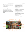
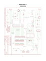
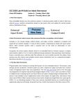
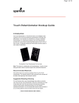
1) Power In: This is the screw terminal where you attach your power source. That can be any battery or
power supply 7.5v to 15v. Note that you should have the power source attached to the board even during
programming, due to USB protecting measures.
2) Power Led: It is on if power is applied correctly on GRoboduino.
3) Digital Ports (0-7): General Purpose digital ports for use with sensors, servos, relays etc. Ports 0, 1 are
also connected to the hardware serial port of AVR processor.
Ports 3, 5, 6 are capable of use with hardware PWM (analogWrite command of Arduino)
4) Reset Button: Used rarely, in cases the processor has to be restarted manually.
5) FTDI Connector: This is where your FTDI is connected. FTDI is a usb-to-serial converter, used to
connect the on-board serial port to the USB port of a PC, to program the Arduino or for debugging /
communication purposes. For standalone applications this is used only during programming.
6) Quad 2-input NAND Gate: This IC is used in-circuit between the processor and the
H-Bridge so that the connection requires less pins. This is used internally and you will never need to
worry about it.
7) Motor Connector: Screw terminals for connecting the motors. “L” and “R” marks on the PCB are for
Left and Right motor accordingly.
8) H-Bridge: Dual H-Bridge, 600mA / motor (1.2A peak), L293DNE. For information on how to use
motors / h-bridge easily with the GRoboduino Library, skip to the section “Using GRoboduino Library”.
9) Motor Power Select Jumper: This jumper sets the power supply for the motors. You have two choices:
Vcc (5v, from the on-board regulator, maximum 2A) or Vin (7.5v-15v, from the Power In of the board).
Warning: If you remove the jumper, the motors will not function at all.
10) Analog Ports (0-5), Digital Ports (15-19): These ports can be used for analog sensors (using the
analogRead command of Arduino). They are connected to the Analog-to-Digital converter of the AVR.
There is also a REF pin to be used for setting a reference voltage other than the AVR's standard reference,
if that is necessary.
Alternatively, these ports can be used as digital ports.
11) LED: This is the LED you find in every Arduino board, connected on Pin 13. The GRoboduino Library
contains commands for manipulating the led with great ease, like “toggleLed”, “setLed”. Find more
information about these commands in the “Using GRoboduino Library” section.
12) Buzzer: This is a generic Buzzer used for making sounds or music. The GRoboduino Library contains
commands like “beep”, “playNote” for the buzzer. Find more information about these commands in the
“Using GRoboduino Library” section.
13) Vin – Power In Connector: These pins are very useful in those cases when you need to supply another
pcb with the power source you are supplying the GRoboduino and you don't want to cut and solder new
cables. For example, when using a 12v relay, and you supply GRoboduino with 12v, you can use these
pins to supply the transistor-relay pcb with 12v.
14) Regulator: 78S05 regulator. It gets voltages from 7.5v - 15v and converts them to stable 5v, up to 2A.
Warning: when you use sensors / servos etc that draw more than 1A, it is strongly recommended to attach
a heatsink on the regulator! Also, never touch the regulator, it can get very hot!
3
Getting Started:
Requirements:
• Arduino IDE (http://www.arduino.cc) (or alternative)
• FTDI
•
•
a Battery / Power Supply (7.5v – 15v)
GRoboduinoBoard Arduino Library
(download from http://dexterslabgr.blogspot.com)
1. Install GRoboduinoBoard Library (extract “GroboduinoBoard” folder from the archive to the
“libraries” folder of your Arduino IDE installation)
2. Connect your FTDI on the “FTDI Connector” of GRoboduino and of course your USB.
3. Connect your power source (7.5v – 15v) on the “Power In” screw terminals.
4. If you are using motors (hooked up on the “Motors Connectors” screw terminals) do not forget to select
the power source of the motors (by using “Motor Power Select Jumper”)
Warnings:
•
When applying loads exceeding 1A, putting a heatsink on the regulator is strongly
recommended.
•
Power from USB has been disabled to protect the port. That means, you need to apply power to
the GRoboduino even during programming.
•
If you remove the “Motor Power Select Jumper” the motors will not function. You must select
between Vcc (5v) or Vin (Power In).
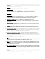
Inside Arduino IDE:
Select “Arduino Duemilanove with ATMega328” Board
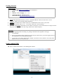
4
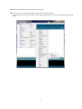
Select the Serial Port that was assigned on your FTDI
You can try one of the examples (Blink, GenericTest, ObstacleAvoider).
Even the “Blink” example can teach you many things about how you can use the GRoboduino peripherals
easily.
5
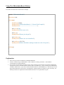
Using The GRoboduinoBoard Library
Let's take for instance the “GenericTest” example:
#include "GRoboduinoBoard.h"
GRoboduino brd;
void setup()
{
Serial.begin(9600);
Serial.println("GRoboduinoBoard v1.2 GenericTest Example");
Serial.println("----------------------------------------");
brd.setLed(ON);
Serial.println("Led is now on");
brd.beep();
Serial.println("Buzzer just beeped");
brd.initMotors();
Serial.println("Motors are now initialized");
brd.setMotors(150, 150);
Serial.println("Motors should be running forward now with 150 speed");
}
void loop()
{
}
Explanation:
First of all you need to include the "GroboduinoBoard.h"
Create a variable of type “GRoboduino”. That variable is actually your board – with methods
(commands) for all the peripherals.
If you want to use the motor controller, in the “setup” section of your program you need to initialize the
asynchronous motor controller handler with the method “initMotors()” (in this example, the GRoboduino
variable is called “brd”, so you can see the command written as “brd.initMotors()”). After that you can set
the speed and direction of the motors, and keep them running without any delays in your main loop - the
interrupt code that is responsible for the PWM of the motors is as optimized as it gets!
6
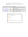
GRoboduino Methods / Commands:
So, these are the class methods of GRoboduino class.
If you don't know what a class method is, then what you should keep in mind is, that the following
commands are used after the variable name of the GRoboduino and a dot (.).
For instance, if you have created a GRoboduino variable named “board”:
- for initializing the motors you would write: board.initMotors();
- for making a beep sound: board.beep();
etc.
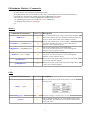
Motors:
Command & Parameters
Result Type Description
initMotors()
void
This is called usually in the “setup” section of the program,
when motors will be used. It is absolutely needed for the motor
process to work, and ot needs to be called just one time.
setLeftMotor(int Speed&Direction)
void
Sets the speed and direction of the Left Motor.
1 to 255 on one direction and -1 to -255 on the opposite
direction. 0 (zero) stops the motors.
setRightMotor(int Speed&Direction)
void
Sets the speed and direction of the Right Motor.
1 to 255 on one direction and -1 to -255 on the opposite
direction. 0 (zero) stops the motors.
setMotors(int Left, int Right)
void
Sets the speed and direction of both the motors.
1 to 255 on one direction and -1 to -255 on the opposite
direction. 0 (zero) stops the motors.
getLeftMotor()
int
Returns the current speed and direction of the Left Motor.
(-255 to 255, 0 means stopped)
getRightMotor()
int
Returns the current speed and direction of the Right Motor.
(-255 to 255, 0 means stopped)
LED:
Command & Parameters
Result Type Description
Sets the state of the led. That can be used in one of the
following ways
setLed(byte State)
void
toggleLed()
void
Turns the led ON if it is OFF and vice-versa.
getLed()
byte
Gets the state of the led (pin 13). The evaluation can be done
using: ON/OFF, 1/0, true/false. So you can use whatever suits
you in your code.
7
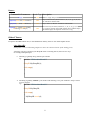
Buzzer:
Command & Parameters
Result Type Description
beep()
void
Makes a single beep sound.
playNote(char Note, int Duration)
void
Plays a musical note (which can be 'c', 'd', 'e', 'f', 'g', 'a', 'b', 'C')
for “Duration” milliseconds.
playTone(int Tone, int Duration)
void
Plays “Tone” (in Hz) for “Duration” milliseconds.
playSong(int Length, char Notes[],
int Beats[], int Tempo)
void
Given an array of Notes (characters, 'c', 'd', 'e', 'f', 'g', 'a', 'b',
'C'), an array of beats, the length of those arrays and the tempo,
this method plays the sequence of notes as a song.
Other Classes:
Except for the GRoboduino class, in the GRoboduino Library there are also other helpful classes:
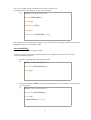
class SharpIR:
(SharpIR is a sensor with analog output so it has to be connected to one of the analog ports)
Assuming you have connected your SharpIR sensor on Analog Port 0, there are two ways
of creating a SharpIR object:
•
Declaring it globally along with the port number
e.g.:
#include "GRoboduinoBoard.h"
SharpIR MySharpIR(0);
void setup()
{
}
•
Declaring it globally without a port number and attaching it to a port inside the “setup” section
of your program.
e.g.:
#include "GRoboduinoBoard.h"
SharpIR MySharpIR;
void setup()
{
MySharpIR.attach(0);
}
8
One way or another, after the initialization, the object is ready to use.
To read the value from the sensor use the “read” command.
e.g.:
#include "GRoboduinoBoard.h"
SharpIR MySharpIR(0);
void setup()
{
Serial.begin(9600);
}
void loop()
{
Serial.println(MySharpIR.read());
}
The result from “read” command is of type int, and it is the result of averaging 10 sensor readings, as the
SharpIR sensors have very unstable output.
class ParallaxPing:
(ParallaxPing is a sensor with digital output)
Assuming you have connected your ParallaxPing sensor on Digital Port 3, there are two ways of
creating a ParallaxPing object:
•
Declaring it globally along with the port number
e.g.:
#include "GRoboduinoBoard.h"
ParallaxPing MyParallaxPing(3);
void setup()
{
}
•
Declaring it globally without a port number and attaching it to a port inside the “setup” section
of your program.
e.g.:
#include "GRoboduinoBoard.h"
ParallaxPing MyParallaxPing;
void setup()
{
MyParallaxPing.attach(3);
}
9
One way or another, after the initialization, the object is ready to use.
To take a measurement you can use the following commands, depending on the
result you want:
Command & Parameters
Result Type Description
Sends a ping and counts the microseconds to the
return of that ping. The result is a long integer of the
microseconds counted.
pingMicroseconds()
long
distanceInCM()
double
Triggers a measurement and returns the calculated
distance, in centimeters, as a double.
distanceInInches()
double
Triggers a measurement and returns the calculated
distance, in inches, as a double.
e.g.:
#include "GRoboduinoBoard.h"
ParallaxPing MyParallaxPing (3);
void setup()
{
Serial.begin(9600);
}
void loop()
{
Serial.println(MyParallaxPing.distanceInCM(), DEC);
}
10
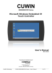
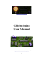
APPENDIX
SCHEMATICS
11