1
ModIO™ M100 Modbus Interface Unit - Users Guide
Page 1
Updated: 16 April 2006
ModIO™ M100
Modbus Interface Unit
User’s Guide
ModIO PCB Rev: 1.2 (aka Rev C)
Firmware Rev: 16
Mach3 Rev: 1.84
Copyright 2006 ©
Homann Designs
Revision 0.92
ModIO™ M100 Modbus Interface Unit - Users Guide
Page 2
Homann Designs
20 View St
HIGHETT VIC, 3190
AUSTRALIA
[email protected]
http://www.homanndesigns.com
Copyright 2005/6 © Homann Designs. All rights reserved.
No part of this publication may be reproduced, transmitted, transcribed, stored in a retrieval system,
or translated into any language or computer language, in any form or by any means, electronic,
mechanical, magnetic, optical, chemical, manual or otherwise, without the prior written permission
of Homann Designs.
Disclaimer
Homann Designs makes no representation or warranties with respect to the contents hereof and
specifically disclaim any implied warranties or merchantability or fitness for any particular purpose.
Information in this publication is subject to change without notice and does not represent a
commitment on the part of Homann Designs.
Feedback
We appreciate any feedback you may have for improvements on this document. Please send your
comments to [email protected]
Trademarks
ModIO™ and DigiSpeed™ are trademarks of Homann Designs. All other brand and product names
mentioned herein are trademarks, services marks, registered trademarks, or registered service marks
of their respective owners and should be treated as such.
Acknowledgements
To get a product like the ModIO to the state that it is now, takes an immense effort. This would not
be possible without the help of the following people and others who have helped by beta testing the
early versions.
Andy Wander - Andy has taken it upon himself to provide front line support for the ModIO, usually
being the first to address questions and problems as they appear on the Yahoo ModIO and Mach
User Groups.
Art Fenerty - Art has worked tirelessly, providing a ModIO interface into Mach3. He is always
open and responsive to new suggestions and possibilities.
Olivier Adler - Olivier convinced us that ModBus was the way to go for a reliable serial
communications protocol. Additionally, he conducted the ModIO RS-485 interface testing,
identified a number of required safety features and has always provided valuable feedback.
John Prentice - John has transformed this document from its incomplete draft state into a polished
manual. Additionally, behind the scenes John has been a sounding board and a great support during
the development of the ModIO.
Steve Blackmore - Steve has always provided sound advice and feedback on various aspects of the
ModIO development.
Copyright 2006 ©
Homann Designs
Revision 0.92
ModIO™ M100 Modbus Interface Unit - Users Guide
Page 3
Table of Contents
1
Introduction ............................................................................................................................ 5
1.1 Contents............................................................................................................................ 5
1.2 Features............................................................................................................................. 5
2
Quick Start Guide ................................................................................................................... 7
2.1 What you need .................................................................................................................. 7
2.2 Configuring Mach3/IV ...................................................................................................... 8
2.3 Lighting an LED ............................................................................................................. 10
2.4 Sensing a switch closure.................................................................................................. 12
3
Board Description ..................................................................................................................13
3.1 Introduction..................................................................................................................... 13
3.2 Overview ........................................................................................................................ 13
3.3 Connectors ...................................................................................................................... 13
3.3.1
Connector summary................................................................................................13
3.3.2
I/O Connectors (J1, J10) .........................................................................................13
3.4 Jumpers........................................................................................................................... 16
3.5 Power Supply.................................................................................................................. 16
3.6 Reset Switch ................................................................................................................... 17
3.7 Configurations and Slave address switch......................................................................... 17
3.7.1
Configuration parameters........................................................................................17
3.7.2
Slave addressing .....................................................................................................18
3.8 Status LEDs .................................................................................................................... 19
3.8.1
Power LED.............................................................................................................19
3.8.2
Error LED...............................................................................................................19
3.8.3
Transmit/Receive LEDs..........................................................................................19
3.8.4
Pin status LEDs ......................................................................................................19
3.9 Modbus Communication interface................................................................................... 20
3.9.1
RS-232 versus RS-485............................................................................................20
3.9.2
RS-232 Interface.....................................................................................................20
3.9.3
RS-485 interface .....................................................................................................20
3.10 Discrete Inputs .............................................................................................................. 21
3.11 Discrete Outputs............................................................................................................ 22
3.12 Expansion Module Interface .......................................................................................... 23
3.13 DigiSpeed™ DC Motor Controller Interface ................................................................. 23
4
ModIO support in Mach3 .......................................................................................................24
4.1 Introduction to data – the autopoller and macropump ...................................................... 24
4.2 Configuring Mach communications for a ModIO ............................................................ 24
4.3 Enabling the ModIO interfaces........................................................................................ 25
4.4 Configuring Inputs & Outputs ......................................................................................... 27
4.5 Configuring MPGs .......................................................................................................... 27
4.6 Configuring the DigiSpeed spindle control...................................................................... 27
4.7 Using analog inputs......................................................................................................... 28
4.8 LCD Display................................................................................................................... 30
4.9 Scanned keyboard ........................................................................................................... 30
4.10 Frequency measurement ................................................................................................ 31
4.11 Testing ModIO from Mach3.......................................................................................... 31
4.11.1 Opening the ModIO for test ....................................................................................31
4.11.2 Reading registers ....................................................................................................31
4.11.3 Writing a register ....................................................................................................32
Copyright 2006 ©
Homann Designs
Revision 0.92
ModIO™ M100 Modbus Interface Unit - Users Guide
5
6
7
8
9
Page 4
Interfacing some typical devices to ModIO ............................................................................33
5.1 Output devices ................................................................................................................ 33
5.1.1
External LED or lamp.............................................................................................33
5.1.2
Relay ......................................................................................................................33
5.1.3
Logic gate (e.g. on VFD invertor) ...........................................................................33
5.2 Input devices ................................................................................................................... 34
5.2.1
Push switches (galvanic contact).............................................................................34
5.2.2
From logic gate outputs ..........................................................................................34
5.2.3
MPGs .....................................................................................................................35
5.2.4
Rotary potentiometers.............................................................................................35
5.2.5
Rotary switches as potentiometer ............................................................................35
Register Organization.............................................................................................................36
6.1 ROM Register Block....................................................................................................... 37
6.2 Configuration Register Block .......................................................................................... 37
6.2.1
100 - ADDRHI: Modbus Unit ID address high nibble............................................39
6.2.2
101 - CONFIG: Configuration control register........................................................40
6.2.3
102 - COMM0: UART Configuration Control Register.........................................41
6.2.4
103 - FLASH: Flash control register .......................................................................42
6.2.5
104 - PUMP: Pump Control Register ......................................................................44
6.2.6
105 - DEBUG: ModIO™ Debug control register. ...................................................46
6.2.7
106 - CONFIG2: Configuration control register 2 ..................................................47
6.3 RAM Register Block....................................................................................................... 48
6.3.1
1000 - 1039 Liquid Crystal Display Controller registers .........................................49
6.3.1.1
LCD data Registers .........................................................................................49
6.3.1.2
LCD Connector Interface ................................................................................49
6.3.1.3
Register Use Summary....................................................................................50
6.3.2
1040 - DOUT: Discrete Output Register .................................................................51
6.3.2.1
Bit allocation in DOUT ...................................................................................51
6.3.2.2
Discrete Output Safety Charge Pump ..............................................................52
6.3.2.3
Register Use Summary....................................................................................52
6.4 1041 – SSPEED: PWM for DigiSpeed unit ..................................................................... 53
6.4.1
1050 - Encoder1: MPG Encoder read register .........................................................54
6.4.1.1
Overview ........................................................................................................54
6.4.1.2
Register Use Summary....................................................................................54
6.4.2
1151 - DIN: Discrete Input Register........................................................................55
6.4.3
1152 , 1153, 1154 – Analog in Registers.................................................................57
6.4.3.1
Overview ........................................................................................................57
6.4.3.2
Register Use Summary....................................................................................57
6.4.4
1155 – Encoder2: MPG Encoder read register.........................................................58
6.4.4.1
Overview ........................................................................................................58
6.4.4.2
Register Use Summary....................................................................................58
6.4.5
1156 – TickCtr: Timing register..............................................................................59
6.4.6
1157 – Period: Spindle speed measurement register ...............................................59
6.4.7
1158 – Keyboard: Scanned inputs register..............................................................60
Firmware programming..........................................................................................................61
7.1 Preparation...................................................................................................................... 61
7.2 Connecting to the ModIO and erasing flash..................................................................... 62
7.3 Programming .................................................................................................................. 62
Revision data .........................................................................................................................63
Index......................................................................................................................................64
Copyright 2006 ©
Homann Designs
Revision 0.92
ModIO™ M100 Modbus Interface Unit - Users Guide
1
Page 5
Introduction
Thank you for purchasing Homann Designs' ModIO™ M100 Modbus interface unit. The M100
provides a general purpose interface unit with a Modbus RS-232 and RS-485 serial interface for
communication with a Modbus Master.
This document is a User's Guide that describes the ModIO™ M100 Modbus interface unit. The
document contains information on how to use and integrate the board into your own systems.
1.1 Contents
The box received when ordering the ModIO™ M100 Modbus interface unit. contains the
following:
•
The ModIO™ M100 Modbus interface board
•
A serial cable, DB9-male to 10 pin 2 x 5, 0.1" boxed header , for connecting
•
An optional 4x20 Character LCD display for use with the M100.
1.2 Features
Homann Designs' ModIO™ M100 Modbus interface unit lets you quickly and simply add additional
I/O functionality to your CNC system. The M100 provides the following;
•
•
•
•
•
•
Serial Communications
•
Modbus Protocol Stack
•
RS-232 Transceiver, and
•
RS-485 Half or Full Duplex Interface
•
RX and TX communications activity
indicator LEDs
Digital I/O
•
8 Digital 0 - 5 volt logic inputs
•
8 Digital outputs capable of driving
relay coils
•
LED Activity indicators on all inputs
and outputs
Analog Inputs
•
3 Analog inputs with 0 - 5 volt input
•
10-bit resolution (1024 steps)
Quadrature Encoders
•
2 Manual Pulse Generator (MPG)
Quadrature Encoder interfaces
Character LCD Interface
•
For Hitachi HD44780 (industry
standard) controller character displays
•
Up to 4 x 20 character LCD Display.
Safety Charge Pump
•
Disables outputs when Modbus
Communications are interrupted.
•
•
•
•
•
DigiSpeed™ Interface
•
Generates PWM Signals for
DigiSpeed™ Motor Speed controller.
Expansion Module Interface
•
Provides for up to 15 Special purpose
Interface expansion boards.
Power Supply Input
•
+8 to +24 Vdc or +6 to +12Vac via
screw terminals or,
•
+8 to +24 Vdc or +6 to +12Vac via
2.1mm Coaxial jack
•
Power indicator LED
Firmware Upgrades
•
User upgradeable via serial
interface.
Other Features
•
Error indicator LED for ModIO™ and
communications errors.
•
5mm pluggable screw terminals for
Digital, Analog I/O and Power
connections.
•
Designed to fit into the OKW
B6504111 RailTec DIN Rail
enclosure.
The ModIO™ can be used with any controlling software supporting the Modbus RS-232 or RS-485
standards. In this manual we will use the Mach3 CNC controller when we need to illustrate the
Copyright 2006 ©
Homann Designs
Revision 0.92
ModIO™ M100 Modbus Interface Unit - Users Guide
Page 6
master side of the Modbus interface. A demonstration of Mach3 can be downloaded from :
http://www.artsoft.ca should you not already be using it and want to run the setup procedures
described in the manual.
Copyright 2006 ©
Homann Designs
Revision 0.92
ModIO™ M100 Modbus Interface Unit - Users Guide
2
Page 7
Quick Start Guide
This section is intended to allow you to set up your new ModIO™ with a single switch and to use
Mach3 to read its state and to control one of the output LEDs of the ModIO™. Initially you should
use the RS-232 interface, even though you may eventually want to use RS-485. When you have
successfully done this you will have experience which will help you understand the information in
subsequent chapters.
We cannot too strongly advise you to follow these simple tests if you have not used a ModIO™
before. Its neat appearance belies a large number of configurable facilities. In addition you must
ensure that the software in the PC (the master) and the ModIO™ (the slave) are compatibly
configured. The serial communications cannot be simply diagnosed with a multi-meter or logic
probe in the way that the connections between parallel port and breakout board can. If you do
encounter any difficulties then an understanding of what you are aiming to do and a systematic set
of testing steps will ensure your success.
This manual contains many diagrams showing interface connections, but if you
have difficulty in understanding them you are strongly advised to seek assistance
from someone with electronics experience. Incorrect connections could damage the
ModIO™ and/or the equipment to which you are interfacing.
2.1
What you need
To get started you need:
•
a ModIO™ board
•
a toggle or push switch with two flying leads
•
a power supply (e.g. wall-wart aka plug-top transformer) delivering 6 to 18 volts AC, or 8 to
24 volts DC via a 2.1 mm coaxial jack
•
a lead with a D9 Male connector at one end (the ModIO™) and a D9 Female connector at
the computer end
•
a PC with a serial (COM) port available and Mach3 installed on it
•
and, ideally, an LCD connected to the ModIO™
With the power to PC and ModIO™ switched off connect the ModIO™ to the PC by the serial
cable and RS-232 ribbon cable supplied with the ModIO™. This plugs into J7 which is between the
two sets of LEDs which face the edge of the board.
If you have the LCD, plug it into J4
Check that the jumpers are in their default positions as shown in figure 2.1 Notice that the jumpers
and pins have been highlighted for clarity of illustration.
Switch the hex rotary switch (figure 3.4) to “0” (zero) – This gives the default configuration of all
ModIO parameters (e.g. baud rate, slave address etc.).
Plug in the power jack
Turn on the computer and ModIO™ power supply. The green power LED on the ModIO, should
light. See figure 3.4. The LCD should display text similar to figure 3.3. – in particular be sure to
check that “–DEF” is shown on the bottom line. If it is not then the hex switch is not correctly set.
Copyright 2006 ©
Homann Designs
Revision 0.92
ModIO™ M100 Modbus Interface Unit - Users Guide
Page 8
Next you need to tell Mach3 about your ModIO™.
Figure 2.1 – Standard jumpering for use with RS-232
2.2 Configuring Mach3/IV
Double click the Mach3 icon – not Mach3Mill. Click
Create Profile. And fill in the new name and highlight
that you want it cloned from Mach3Mill. If you have
another profile you normally use then you can clone
from this. See figures 2.2 and 2.3.
You can either create a new shortcut for your profile (see
Using Mach3Mill manual) or run Mach3.exe and select
from the list of profiles
In this manual we will assume that you are using the
standard 1024.set screens. The ModIO™ will however
work with any screen set.
Figure 2.2 – Creating new Profile
If you are testing the ModIO™ on a computer that does
not have your machine tool connected to it then you will
need to work in the Offline mode to be able to clear the
EStop condition.
On Config>Ports and Pins, Port Setup & Axis Selection
tab, check ModBus Input/Output support. Close Mach3
and reload it with your ModIOTest profile
Figure 2.3 – Naming and cloning
Copyright 2006 ©
Homann Designs
Revision 0.92
ModIO™ M100 Modbus Interface Unit - Users Guide
Page 9
Open the dialog from the Config>Setup ModBus Control menu. It will look like figure 2.4
Figure 2.4 – A default Modbus configuration in Mach3
This complex looking screen allows Mach3 to be used with virtually any Modbus device – e.g. a
custom programmed PLC.
Mach3 is aware of the arrangement of registers in the ModIO™ and will replace this arbitrary
configuration with one optimised for ModIO™ when you check the MODIO ModBus card
checkbox. The screen will then look like figure 2.5.
Figure 2.5 – Mach3 set for ModIO
It is assumed that you are plugged into COM1 on your PC. The baud rate and async parameters are
set to 57600 and 8-1-N which is the ModIO™ default. Use RTS is only relevant to half-duplex RSCopyright 2006 ©
Homann Designs
Revision 0.92
ModIO™ M100 Modbus Interface Unit - Users Guide
Page 10
485 operation and the default serial timeout of 50mS is suitable for all applications.
At this stage the green LED to the left of the RS-232 cable should be giving and intermittent
double-flash about every half second. This shows that
data is being received by the ModIO™.
The details of the Autopoller are described later in
chapter 4. For now, notice only that the Slave Address
is set to 1 in Mach3 whereas the ModIO™ default is 6.
Change the screen as shown in figure 2.6 and click
Apply.
When you do this you should notice that the status
message Receive Timeout at the top of the screen
should change to No Error. The flashing green LED
will speed up and the red one above it will also flash.
The red LED shows that the ModIO™ is recognising
the received data (because the slave address is correct)
and transmitting replies.
Figure 2.6 – Setting slave address
There is no point in going further if you cannot get the regular red/green flashing when the
ModIO™ is connected to your running Mach3. Recheck connections, that the ModIO™ is running
the default configuration and that the Config>Setup ModBus Control dialog looks correct.
If all is well you can control your first output device.
2.3 Lighting an LED
The ModIO™ has 8 digital outputs each with an indicator LED on the board. If the power jack is on
the right hand side of the board then these LEDs are above the connector on the bottom edge.
The outputs are numbered 0 to 7 from left to right. These numbers correspond to setting Port 0
“Pins” 0 to 7 in the Config>Ports and Pins, Output Signals tab.
Within Mach3 the
outputs which can be
controlled from parallel
port, ModIO™ or, in
MachIV, the GRex are
numbered 1 to 20.
Figure 2.7 shows Mach
output #3 configured to
ModIO™ Discrete
Output 6.
Do this on your system
and click Apply.
Now if you change the
Figure 2.7 – Mach Output 3 configured to ModIO discrete output 6
Active Low column for
your output you will be
able to turn the LED (next to the right end for Discrete Output 6) on and off.
Figure 2.8 shows LED 6 on and figure 2.9 shows the corresponding screen setting.
Copyright 2006 ©
Homann Designs
Revision 0.92
ModIO™ M100 Modbus Interface Unit - Users Guide
Page 11
In practice, of course, an output would
be controlled by something like
M07/M08 (coolant) or a user macro in
Mach3.
You can show this by using
Config>Ports and Pins, Spindle tab to
set Mach3 output 3 to be the Flood
coolant control. Then your LED will
turn on if you MDI an M08 or use the
Flood coolant button and turn off with
an M09.
Figure 2.8 – LED 6 is ON
Figure 2.9 – Config for LED 6 to be ON
You might be confused by all the numbering so it is
worth summarizing it.
•
Every output signal in Mach3 has an internal
number (1 to 20)
•
In Config>Ports and Pins, Output Signals you link
(or map) these to a port and a “pin” number on
that port
•
ModIO™ ouputs (and inputs come to that) are all
referred to as being on Port 0 (zero). Printer ports
are 1 and 2.
•
The 8 ModIO™ Discrete Outputs are named
Figure 2.10 – Coolant is ModIO
DOut0 to DOut7 (left to right if the connector is at
Output 6
the bottom as you view the board) and, for
example, DOut 6 is what Mach3 thinks is Port 0 Pin 6.
And finally:
•
The actual outputs are connected to numbered terminals (plugged onto pins) on the
ModIO™. So for example the signal DOut 6 is on terminal 16 – sometimes called pin 16.
These numbers are defined in Table 3.1
It seems complicated but unfortunately necessary because of the power of the system.
Next you can move on to see how a switch input can be used.
Copyright 2006 ©
Homann Designs
Revision 0.92
ModIO™ M100 Modbus Interface Unit - Users Guide
Page 12
2.4 Sensing a switch closure
Switch off the ModIO™ power and connect a normally open switch between terminals 5 and 8 on
the Input side of the ModIO™. These
terminals are Ground and input DIn 1
respectively.
Note: Take care not to do this on the output
side by mistake.
Switch on the ModIO™ power. When you
press the switch the second light from the
left (if power jack is on right hand edge of
board) should light. If it is on and goes off
when switch pressed the you have a
normally closed switch by mistake.
The connections are shown in figure 2.11.
Now go to Config>Ports and Pins, Input
Signals tab and define input #3, say, to be
Port 0 (i.e. the ModIO™) Pin 1 (i.e. Din 1).
This is shown in figure 2.12
Figure 2.11 – Switch connected to terminals
5 and 8 of Input side of ModIO
When you go to the Mach3 Diagnostics
screen you will see
Input #3 lighting
when you press the
switch.
Note: If you are
following very
carefully you
might spot that we
have the switch
Figure 2.12 – Configuring a ModIO input
connected so it
pulls the input low when active but did not select Active Low in Config>Ports and Pins. This is a
feature (or perhaps more properly bug) of the current release of Mach3.
If your ModIO™ works with these two simple tests then you are in a position to configure it and
Mach3 interfaced to an actual machine tool. Congratulations!
The next chapter gives details of all the physical interfaces.
Copyright 2006 ©
Homann Designs
Revision 0.92
ModIO™ M100 Modbus Interface Unit - Users Guide
3
Page 13
Board Description
3.1 Introduction
4 no. Holes 3mm dia.
This section tells you about the
mechanical and electrical aspects of the
ModIO™ board.
On first reading you probably do not need
to read beyond the description of the
LEDs and their functions.
The board is 82mm x 98 mm excluding
wiring space from the screw connectors.
The total thickness is approximately
25mm. Figure 3.1 shows the position of
the mounting holes.
View from component side
50
3.2 Overview
15
82
Power Connector
Here
6.5
85
98
Figure 3.1 – Board outline and fixings
3.3 Connectors
3.3.1 Connector summary
The ModIO™ contains a number of connectors by which the board is interfaced to the PC, your
machine tool and its control panel and a power source. The connectors are listed in Table 3.1 below.
The location of the connectors is indicated in Illustration 3.2 below.
Connector
Description
Comment
J1, J10
I/O Connectors
18 Pin pluggable screw connectors
J4
LCD Interface
16 pin 2 x 8, 0.1” IDC header
J6
Expansion Bus
10 pin 2 x 5, 0.1” IDC header
J7
RS-232 Interface
10 pin 2 x 5, 0.1” IDC header
J8
Power Jack
2.1mm Coaxial Power jack
J15
DigiSpeed™ Control
6 Pin Molex 0.1" single row header
Table 3.1 - Connector Summary
3.3.2 I/O Connectors (J1, J10)
The ModIO™ contains 2 connectors for interfacing to the machine tool and its control panel. Each
connector (J1 and J10) is made up of 18 pluggable screw terminals. Being pluggable, they may be
“lifted off” their pins to aid servicing and installation. The identification of each terminal is listed
below in Table 3.2 and Table 3.3 below.
Copyright 2006 ©
Homann Designs
Revision 0.92
ModIO™ M100 Modbus Interface Unit - Users Guide
Page 14
Figure 3.2 – Jumper/Connector Identification
Pin number
Signal
I/O
Comment
1
+5v
-
Power Supply (+5V)
2
Analog 1 Input
I
0-5V Analog Input
3
Analog 2 Input
I
0-5V Analog Input
4
GND
-
Power Supply (GND)
5
Analog 3 Input
I
0-5V Analog Input
6
GND
-
Power Supply (GND)
7
VGnd
-
Connect external VOut supply Ground here
8
+VOut
-
Device supply (VOut) *(It is a power input or output
depending on JP3)
9
DOut0
O
Discrete Output
Shared with Scanned keyboard column select 0
10
DOut1
O
Discrete Output
Shared with Scanned keyboard column select 1
11
DOut2
O
Discrete Output
Shared with Scanned keyboard column select 2
Shared with DigiSpeed Direction
12
DOut3
-
Discrete Output
Shared with Scanned keyboard column select 3
Shared with optional DigiSpeed Enable
13
+VOut
-
Power Supply (VOut)*
Copyright 2006 ©
Homann Designs
Revision 0.92
ModIO™ M100 Modbus Interface Unit - Users Guide
Pin number
Signal
I/O
Page 15
Comment
14
DOut4
O
Discrete Output
Shared with DigiSpeed PWM signal
15
DOut5
O
Discrete Output
16
DOut6
O
Discrete Output
17
DOut7
O
Discrete Output
18
+VOut
-
Power Supply (VOut)* (see pin 3)
Table 3.2 - J1 or J2 I/O Connector (Outputs side)
Pin number
Signal
I/O
Comment
1
RS-485 A+
I/O
RS-485 differential line A+
2
RS-485 A-
I/O
RS-485 differential line A-
3
RS-485 B-
I/O
RS-485 differential line B-
4
RS-485 B+
I/O
RS-485 differential line B+
5
GND
-
Power Supply (GND)
6
+5V
-
Power Supply (+5V)
7
DIn0
I
Discrete Input (0-5V)
Shared with Scanned Keyboard data 0
8
DIn1
I
Discrete Input (0-5V)
Shared with Scanned Keyboard data 1
9
DIn2
I
Discrete Input (0-5V)
Shared with Scanned Keyboard data 2
10
DIn3
I
Discrete Input (0-5V
Shared with Scanned Keyboard data 3
11
GND
-
Power Supply (GND)
12
DIn4
I
Discrete Input (0-5V)
Shared with DigiSpeed Index
Shared with MPG2
13
DIn5
I
Discrete Input (0-5V)
Shared with MPG2
14
DIn6
I
Discrete Input (0-5V)
Shared with MPG1
15
DIn7
I
Discrete Input (0-5V)
Shared with MPG1
16
GND
-
Power Supply (GND)
17
Vac/Vdc
-
Power Supply (VIN)
18
Vac/Vdc
-
Power Supply (VIN)
Table 3.3 - J10 or J12 I/O Connector (Inputs side)
Copyright 2006 ©
Homann Designs
Revision 0.92
ModIO™ M100 Modbus Interface Unit - Users Guide
Page 16
Note:
(a) In this revision of the manual these Data connections have been relabeled from 0 to 7
rather than 1 – 8 to correspond to the bit numberings in DIN and DOUT registers. You do
not need to change any existing wiring - this is only a name change.
(b) For the remainder of this manual we will use the identifications J1 and J10 (these should
be taken as J2 and J12 on boards equipped with the 5.08mm terminals
(c ) Many functions share the DIn and DOut pins with the main discrete input register and
discrete output register. The details are given in the individual sections of the manual. The
terminology DOUT (and DIN) refers to the actual bits of the discrete output (and input
registers) while DOut and DIn refer to the signals whatever their source or destination (e.g.
MPG logic, PWM generator, keyboard scanner etc.)
3.4
Jumpers
The ModIO™ also contains a number of jumper that allow the board to be configured. The
connectors are listed in Table 4 below. The location of the connectors is indicated in figure 3.2.
Jumpers
Description
Comment
Reference
S2
Slave Id/Default
Config
16 position Hex
switch
J13
DigiSpeed™ Enable
source
3 Pin 0.1” Jumper
JP1
Boot Select
2 Pin 0.1” Jumper
See Firmware programming
section
JP2
spare
2 Pin 0.1” Jumper
Leave open
JP3
Vout Source
3 Pin 0.1” Jumper
See Discrete Outputs section
JP4
RX Receive Source
3 Pin 0.1” Jumper
See Communications Section
H/F* (JP5)
RS-485 Duplex Select 2 Pin 0.1” Jumper
See Communications Section
RXP (J6)
RS-485 RX Polarity
2 Pin 0.1” Jumper
See Communications Section
JP7
Not used
JP8
RS-485 A Load
2 Pin 0.1” Jumper
See Communications Section
JP9
RS-485 B Load
2 Pin 0.1” Jumper
See Communications Section
TXP (J10)
RS-485 TX Polarity
2 Pin 0.1” Jumper
See Communications Section
BL (JP11)
LCD Back light
2 Pin 0.1” Jumper
See LCD Section
Default (JP12)
Legacy (was Default
Configuration)
2 Pin 0.1” Jumper
Leave open
JP13
DigiSpeed enable
3 Pin 0.1” Jumper
See DigiSpeed interface
Table 3.4 - Jumper Summary
3.5 Power Supply
Power is connected to the ModIO™ via a 2.1mm Co-axial Power Jack (J8), or from Pins 17 and 18
on the I/O Connector strip J10. The power supply can accept AC or DC power and it does not
Copyright 2006 ©
Homann Designs
Revision 0.92
ModIO™ M100 Modbus Interface Unit - Users Guide
Page 17
matter whether the connector pin is positive or negative although it is usual for the pin to be the
positive pole with a DC supply.
The input voltage should be in the range 8 to 24 volts DC or 6 to 18 volts RMS AC.
Internally the ModIO™ conditions this raw power supply by a full-wave bridge rectifier feeding
into a 500mA linear voltage regulator. The heat dissipation of this regulator can cause excessive
temperature rise in a small enclosure or when input voltages are at the higher end of the range. The
internal supply presents 5volts DC and/or the unregulated (but rectified) raw input to various output
terminal. Sufficient power is available for potentiometers, the LCD backlight, a few low power
LEDs or relays, etc. but if industrial MPGs or other higher powered devices are to be used then you
need to provide your own supply for them with its ground commoned to the ModIO™ ground.
3.6 Reset Switch
A small push button is mounted on the ModIO™ printed circuit behind output terminal number J17. This will reset the ModIO™.
Note: No changes in configuration either by software or jumper take effect until the ModIO™ is
reset by this button or by cycling the power off and on. Forgetting to do this is a source of many
reports of difficulty in configuring the ModIO™.
3.7 Configurations and Slave address switch
3.7.1 Configuration parameters
The ModIO™ remembers how
it is configured in an area of
flash memory in the PIC chip.
This configuration is updated by
writing to registers of the
ModIO™. In a Mach3
installation this will generally be
done using the Config dialog but
can also be done by using the
test screen and writing into the
numbered registers. If you have
an LCD connected then, until
you overwrite the screen (e.g.
from Mach3) it will display the
programmed configuration. In
part this is in clear language and
in part by letters indicating the
state of configurations bits. A
Figure 3.3 – Configuration display on LCD
capital version of the letter
indicates that the feature is
Enabled a lowercase letter that it is Disabled.
The following symbols are displayed in this order:
Function
Enabled Disabled
Discrete outputs
D
Copyright 2006 ©
Homann Designs
d
Notes
J1 Pins 9-12 & 14 - 17
Revision 0.92
ModIO™ M100 Modbus Interface Unit - Users Guide
A
L
1
H
2
P
F
K
a
l
m
h
m
p
f
k
Enforce serial interchar gap rules G
Limit serial error flash to duration E
of error state
ModIO debug mode selected
D
g
e
Analog inputs
LCD interface
MPG1
MPG1 Hi-res
MPG2
PWM output for DigiSpeed
Frequency counter
Keypad scanner
Default parameters in use
d
-DEF
Page 18
J1 Pins 2, 3 & 5
J10 Pins 14 & 15
J10 Pins 12 & 13
J1 Pin 14
J10 Pin 4
J10 Pins 7 – 10 & J1 Pins
9 - 12
Hardware/firmware
debug only. If enabled it
Disables the discrete
outputs.
The LCD displays the
programmed values. The
ModIO (after Reset) uses
the default ones.
Illustration 3.3 shows a sample screen display.
3.7.2 Slave addressing
Each Modbus device (and with RS-485 there can be
many on one “bus”) has a Slave Address which
defines the messages to which it will respond. This is
configured by a 16 position miniature rotary switch.
See figure 3.4. Position 0 of this switch is reserved to
define the Default Configuration.
Note: Changes to the switch do not take effect until
after the ModIO™ is reset.
Figure 3.4 – Slave address switch and
power LED
Note: It is Highly recommended that you operate the ModIO™ with the
default configuration (switch position = 0 selected) until there is a
need to alter the unit’s configuration and you become confident
understanding the operation of the ModIO™.
To enable the Default configuration:
1. Switch the slave address switch to “0”
2. Press the Reset Switch, or cycle the power to the ModIO™.
On Bootup, the ModIO™ will be configured to:
•
Modbus Slave address of 6
•
Communication settings of 57,600 Baud, 8 bit data, 1 Stop bit, No parity
Copyright 2006 ©
Homann Designs
Revision 0.92
ModIO™ M100 Modbus Interface Unit - Users Guide
•
•
•
•
•
•
•
•
Page 19
LCD Interface Enabled
Discrete I/O Interface Enabled
Analog Interface Enabled
MPG 1 & 2 Enabled (Hi Resolution Mode)
Limit Error Flash Enabled
Flash Discrete outputs Disabled
DigiSpeed™ Interface Disabled
Debug Interface Disabled
Note: If you have the LCD display connected then it will indicate the configuration currently
programmed into the ModIO™ not the parameters of the Default configuration that you will be
using. This is state is indicated by the characters “-DEF” on the bottom line of the display.
3.8 Status LEDs
3.8.1 Power LED
The green LED on the edge of the board by the Slave Address switch shows that the board has 5
volt power available.
3.8.2 Error LED
The red LED above the Power LED is an “Error Indication”. The LED is capable of indicating 2
types of errors:
• Flashing – Modbus Communication Error. Indicates that a error has been detected during
serial communications.
• Solid – ModIO™ Internal Error. Indicate an error internally within the Unit. Selecting an
invalid Slave address will cause such an error
Note: The Modbus Specification requires that once an error is detected, the indicator remains
latched until the unit is reset. This feature can be inconvenient when debugging communication
errors such as an intermittent fault. The ModIO™ contains a configuration bit, LEF, [b2 in register
102 COMM0] that allows the latching of an error to be disabled. When this bit is 1 the Indicator
will extinguish shortly after the error condition is removed.
3.8.3 Transmit/Receive LEDs
The LEDs mounted on the board edge to the left of the RS-232 connector indicate the reception of
data by the ModIO™ (green) and transmission of data by it to the PC (red).
Hint: When Mach3 is running if the green LED flashes but red LED is not flashing then it is
almost certain that the values of slave address are configured differently in Mach3 and the
ModIO™.
3.8.4 Pin status LEDs
Each of the 8 discrete outputs and inputs has a surface-mount LED on the board near to its terminal.
The LEDs indicate an active (i.e. Lo) state on the corresponding pin.
Note: On first reading you may wish to skip the remainder of this chapter.
Copyright 2006 ©
Homann Designs
Revision 0.92
ModIO™ M100 Modbus Interface Unit - Users Guide
Page 20
3.9 Modbus Communication interface
3.9.1 RS-232 versus RS-485
The ModIO™ contains an RS232 and RS-485 serial interface. Both of these interfaces are used by a
single UART on the ModIO™. Therefore only one of the interfaces may be used at any one time.
3.9.2 RS-232 Interface
The connector for this bus is a 10 pin 2 x 5, 0.1" boxed header. The pins and signals for the
connector are detailed in Table 3.5 below.
Pin number
Signal
I/O
Comment
1
N/C
-
-
2
N/C
-
-
3
TX Data
O
RS-232 Data transmitted from ModIO
4
N/C
-
-
5
RX Data
I
RS-232 Data Received by ModIO
6
N/C
-
-
7
N/C
-
-
8
N/C
-
-
9
GND
-
Power Supply (GND)
10
N/C
-
-
Table 3.5 - RS-232 Interface Connector
3.9.3 RS-485 interface
The RS-485 interface should be used if connections of longer than 3 metres are required between
the ModIO™ and the computer or if it is to be operated in an electrically noisy environment (e.g.
with a plasma cutter)
RS-485 allows more than one ModIO™ on the bus (i.e. with different slave addresses) although this
is not at present supported by Mach3.
RS-485 can be used with two or four wire connexions. Although both are supported by ModIO™ it
is strongly advised not to use the 2-wire option with Mach3. The reason for this is that Windows is
not reliable in generating a signal from a Com port to define the direction of information transfer.
With 4-wire this is unnecessary as one pair is transmit and the other pair is receive.
The RS-485 signals are connected via pins 1 to 4 on J10 (or J12). The PC end of the connexion will
require an RS-232 to RS-485 converter. These are available as standard stock items from
electronics and computer suppliers.
The RS-485 mode has various jumpering option as described in Table 3.4
The meaning of these jumpers is as follows:
RX Receive source (JP4)
Should be in position 1-2 for RS-485 communications and position 2-3 for RS-232
Copyright 2006 ©
Homann Designs
Revision 0.92
ModIO™ M100 Modbus Interface Unit - Users Guide
Page 21
communications. If it is in the wrong position then data will not be received from the interface
intended.
RS-485 Duplex Select (H/F)
Should only be inserted in the exceptional event of using 2-wire (half duplex) operation
RS-485 Receive polarity (JP6)
Normally open – jumper to invert Mark/Space polarity
RS- 485 A load (JP8)
This jumper should be in for the last (only) ModIO™ on the bus. It terminates the line with a 120R
load
RS-485 B Load (JP9)
This jumper should be in for the last (only) ModIO™ on the bus. It terminates the line with a 120R
load
RS-485 TX Polarity (JP10)
Normally open – jumper to invert Mark/Space polarity
3.10 Discrete Inputs
The ModIO™ provides 8 Discrete inputs
(Din0 to DIn7) which feed the DIN
register. Some also are used for the MPGs
and the scanned keyboard logic. These
are accessed via pins on J10.
They operate as “Active Low”. That is,
the input device needs to connect the
relevant DIn pin to Ground to represent
the active state.
Each input contains a pull-up resistor,
allowing it to be used with switches or
open-collector outputs on MPGs and the
like.
Each input is provided with a LED,
indicating when the input is active.
Figure 3.5 - Discrete Input Schematic
If the input is being connected to a
switching device other than a passive
switch, the voltage from the device should not exceed 5 volts DC or the inputs will be damaged.
When state of a Discrete input is accessed by the DIN input register, the register contains a bit for
each discrete input. The bit is set “1” when the input is active (i.e. tied to <0.8 volts and LED is
illuminated)
The ModIO™ may be configured to disable the discrete inputs and outputs. That said, it would be
unusual to have a need to do so. To disable the discretes set bit UDIS (CONFIG<2>) to 0.
Copyright 2006 ©
Homann Designs
Revision 0.92
ModIO™ M100 Modbus Interface Unit - Users Guide
Page 22
3.11 Discrete Outputs
The ModIO™ provides 8 Discrete outputs accessed via the Discrete Output Register (DOUT), the
Digispeed feature and the scanned keyboard.
The outputs operates as “Open Collector”. That is, the output is pulled near to ground when active.
Devices that are to be controlled need to be connected between the VOut terminal and a particular
DOut terminal.
The outputs (0 to 6) use the ULN2003A transistor output driver chip. This driver contains an
integral free-wheeling or catch diode, allowing inductive loads such as relay coils to be controlled.
The ULN2003A is rated for
500mA per output.
Output & uses a FMMT491
transistor rated at 200mA.
Each output is provided with a
LED, indicating when the
output is active.
Note: that the ModIO™ power
supply is only capable of
supplying 500 mA in total.
Therefore for high current
applications VOut needs to be
powered from an external
power supply.
There are three sources for
supplying power to the Discrete
outputs. The source is
controlled by Jumper J3, as
detailed below;
Figure 3.6 - Discrete Output Schematic
1. External supply to VOut
Terminal – Remove J3
completely. By removing J3, the VOut terminal is isolated from the rest of the ModIO™
power supply. Power for the devices connected to VOut must be provided externally and is
to be connected between a VGnd terminal and the VOut Terminal.
2. VIn Supply – By placing Jumper J3 between pins 2 and 3, Power for VOut is sourced from
the VIn power supply. It is tapped into the supply after Vin has been full wave rectified but
before it is regulated.
In this case power can be taken from the VOut terminals but an external supply must not be
connected to it.
3. +5V Supply – By placing Jumper J3 between Pins 1 and 2, power for VOUT is sourced
from the ModIO™ internal voltage regulator.
In this case power can be taken from the VOut terminals but an external supply should not
normally be connected to it.
This internal source is not recommended as the power supply has limited capacity.
Copyright 2006 ©
Homann Designs
Revision 0.92
ModIO™ M100 Modbus Interface Unit - Users Guide
Page 23
3.12 Expansion Module Interface
The ModIO™ contains a proprietary expansion bus, based on the I2C serial communication
standard. The connector for this bus is a 10 pin 2 x 5, 0.1" boxed header. The pins and signals for
the connector are detailed in Table 3.6 below.
Pin number
Signal
I/O
Comment
1
+VOut
-
Power Supply (+VOut)
2
+VOut
-
Power Supply (+VOut)
3
+5V
-
Power Supply (+5V)
4
+5V
-
Power Supply (+5V)
5
GND
-
Power Supply (GND)
6
Clock
O
Expansion Bus Clock
7
GND
-
Power Supply (GND)
8
Data
I/O
9
GND
-
Power Supply (GND)
10
GND
-
Power Supply (GND)
Expansion Bus Bidirectional Data
Table 3.6 - J6 Expansion Bus Connector
3.13 DigiSpeed™ DC Motor Controller Interface
The ModIO™ contains an interface for the Homann DigiSpeed™ DC Motor controller. The
connector for this bus is J5, a 6 pin, 0.1” open header. The pins and signals for the connector are
detailed in Table 3.7 below.
Pin number
Signal
I/O
Comment
1
GND
-
Power Supply (GND)
2
PWM
O
DigiSpeed™ PWM Signal#
Shared with DOut 4
3
Enable
O
DigiSpeed™ Enable Signal
Shared with DOut3 or jumpered to GND by JP13
4
Direction
O
Motor Direction Signal
Shared with DOut2
5
Index
I
Motor Spindle Index Signal
Shared with DIn4
6
+5V
-
Power Supply to Digispeed (+5V)
Table 3.7 - J5, DigiSpeed™ DC Motor Controller Interface Connector
Copyright 2006 ©
Homann Designs
Revision 0.92
ModIO™ M100 Modbus Interface Unit - Users Guide
4
Page 24
ModIO support in Mach3
This chapter gives you details of the way you configure Mach3 for the full range of input and
output devices and gives examples of some user code to exploit them.
The Mach3 ModBus interface is subject to a proposal for redesign so information here is limited to
that required for use of the current software.
4.1 Introduction to data – the autopoller and macropump
The ModBus interface is a very polite thing. The slave (ModIO™) never speaks until spoken to by
the master (the PC). The implication of this is that the PC has to keep asking the ModIO™ what the
state of its inputs are.
Mach3 has a buffer, called Input, of 128 x 16 bit words for data input to it from the ModBus device
and another, called Output, of another 128 words of data destined to be sent to the ModBus device.
In addition to these buffers is another 40 word buffer used to send data to the LCD.
A task in Mach3 called the AutoPoller runs periodically (by default 20 times per second). The
AutoPoller sends data to the ModBus device and reads data from it. It is responsible for any errors
in transmission etc. Thus the user just has to put data in Output and the LCD buffers and in due
course it will go to the ModBus device. Data retrieved by the user from Input is the latest version of
information from the device.
The first 64 words of Input and Output are mapped into the port 0 input pins and port 0 output pins
respectively. Thus anything that activates or deactivates a pin (e.g. turning on coolant) can change
the data in a ModBus device and data from the device can be treated as a limit switch, OEM trigger
or virtually anything else that can come in on an input pin.
The second 64 words of Input and Output have to be accessed from VB Script code (e.g. in a macro
or on a button). This will very often be done in a Macropump macro. This is code run, rather like
the AutoPoller, periodically. The difference is that the autopoller does standard things but you write
your own MacroPump.
There are endless possibilities for ModBus devices, indeed with a PLC (programmable logic
controller) the system designer actually writes code to run in the device. The ModIO™ is not user
programmable so Mach3 knows what it does and this makes ModIO™ configuration much simpler
than general ModBus configuration. This manual concentrates of the ModIO™ case.
4.2 Configuring Mach communications for a ModIO
In order to use a ModBus device you
must check Use Modbus InputOutput
support on the Config>Ports and Pins,
Port Setup and Axis Selection tab. After
checking this, close and reload Mach3
with your ModIO profile.
You will then be able to access
Config>Setup ModBus Control. This is
illustrated in figure 4.2.
Figure 4.1 – Enabling ModBus support
Copyright 2006 ©
Homann Designs
Revision 0.92
ModIO™ M100 Modbus Interface Unit - Users Guide
Page 25
Figure 4.2 – Configuring ModBus control
Under MODIO Device Support, check MODIO ModBus card. If this was previously unchecked you
will notice that many of the values in the dialog box change automatically.
You are initially advised to work with the default ModIO™ configuration. This corresponds to the
values set by Mach3 when MODIO ModBus card is checked except that you need to alter Slave
Addr to 6 in the two places indicated in figure 4.2.
The other change that might be required is if you are not using COM1 as the serial port. Set Port
Num to the n in the COMn. That you are using.
Do not alter any other values in the dialog – they are there for devices like PLCs.
When you have done this, click Apply and the red and green LEDs on the left hand side of the RS232 header (J7) should be flashing rapidly and “No Error” should be indicated in Status. If this does
not happen revisit the Quick Start guide of chapter 2 and get this going again.
If you click OK the dialog will dismiss but as it is running at the same time as Mach3 will still
appear on the task bar. You can re-open it from there or the Mach3 Config menu whenever
required.
4.3 Enabling the ModIO interfaces
The default configuration is suitable for many applications. It provides 8 discrete inputs, with the
two MPGs enabled in high-res mode (i.e. one cycle of quadrature pulses gives one count) and 8
discrete outputs. The analog inputs are enabled, the LCD interface is enabled. You may however
need to change these and may wish to configure the ModIO™ board. This is done by the Config
button on the ModBus Status & Control dialog which is just below the MODIO ModBus card
checkbox. See figure 4.2.
Copyright 2006 ©
Homann Designs
Revision 0.92
ModIO™ M100 Modbus Interface Unit - Users Guide
Page 26
This Config button opens a
new dialog as shown in
figure 4.3.
Notes:
(a) It is very important to
realize that using this dialog
displays and reconfigures the
ModIO™ hardware. That is
to say it rewrites the data in
the flash memory of the PIC.
(b) If you are set to default
configuration (hex switch
position = 0) then this is not
the configuration actually
being used by the ModIO™
(c) Changes to a hardware
configuration do not occur
until you Reset the ModIO™
Figure 4.3 – Configure ModIO device
(d) If you change some
parameters (e.g. baud rate) and forget them then you may find you can no longer communicate with
the ModIO™ to further configure it. The default configuration at switch position 0 will get you out
of this difficulty. Do not forget you need a Reset after choosing it.
Important note: Even experienced users can get confused and think that the ModIO™ is not
working correctly by forgetting these things
Some explanation of individual controls in this dialog may be useful:
Headings: The register numbers shown by Mach3 in some of the headings are wrong. See chapter 6
for correct details.
Use Pump: The ModIO™ has built in “charge pump” logic to disable outputs if it seems to have
lost contact with the PC. This can cause problems in testing so you may wish to disable the feature.
The feature, if globally enabled, can be disabled on an individual output by output basis using bits
in register 104 via the Test dialog.
Pump delay: See definition of CONFIG (register 101) for the coding of the pump watchdog delay
time.
Use MPG1../Use MPG2….: The screen references to “pins 5, 6” and “pins 7, 8” should read “Input
side terminals 14, 15” and “.. Input side terminals 12, 13” - I.e. DIn 6, DIn7 and DIn 4, DIn 5.
Disable Debug: It is vital to leave this checked unless you have specialist debugging experience. If
enabled then the discrete outputs are Disabled.
Send config: This button writes the configuration selected to the ModIO™ flash.
RESET MODIO: This button is equivalent to pressing the reset button on the ModIO™ board. It
puts a new configuration into use. It is particularly convenient when the ModIO™ is in an enclosure
on the machine.
Copyright 2006 ©
Homann Designs
Revision 0.92
ModIO™ M100 Modbus Interface Unit - Users Guide
Page 27
4.4 Configuring Inputs & Outputs
No special action is required. Inputs DIn 0 to DIn 7 appear as Mach3 “input pins” 0 to 7 on Port 0.
Outputs DOut 0 to DOut 7 are controlled by “output pins” 0 to 7 on Port 0
4.5 Configuring MPGs
It is convenient to use Port 0 pins 6, 7 or Port 0 pins 4, 5 on the Config>Ports and Pins,
Encoders/MPGs tab to record the connections although the MPG mechanism does not involve pulse
counting by Mach3 – it is done in the ModIO™.
Ensure that the MPGs are configured within the ModIO™ (figure 4.3)
Check the MPG #1 and, if required, MPG #2 boxes on the Modbus Status and Control dialog
(figure 4.2).
Use the Cal button on the jogging flyout in Mach3 to tune the MPGs. Unless a fixed step per detent
click is important to you, you should find that Velocity mode is the most responsive way of
working.
4.6 Configuring the DigiSpeed spindle control
The ModIO™ has a custom interface to the Homann Designs DigiSpeed. This device connects in
place of the
potentiometer on VFD
and chopper DC speed
controllers and allows
software control of the
spindle speed.
It is supported by Mach3
in the PWM (pulse width
modulated) mode.
Enable the interface in
the Configure ModIO™
device dialog by
unchecking Digispeed
Off. See figure 4.3. Click
Send Config and
remember to reset the
ModIO™.
Figure 4.4 – Spindle setup
The DigiSpeed uses discrete outputs DOut 3 and DOut 4 (and optionally DOut 2) so you will not be
able to use these for other purposes (e.g. a scanned keyboard).
Use Config>Ports and Pins, Spindle Setup tab to configure Mach3 as shown in the ringed parts of
figure 4.4.
When the S word is set by G-code to the S DRO equal to the maximum speed for the currently
selected pulley then the ModIO™ will output a 100% ON PWM signal giving full input voltage on
the motor drive circuit. Similarly id S is half the maximum speed then a 50% PWM signal will be
generated.
Configure a Mach3 output signal (#2 in the example above) to be Port 0 Pin 2 (=DOut 2) to control
the motor direction.
Copyright 2006 ©
Homann Designs
Revision 0.92
ModIO™ M100 Modbus Interface Unit - Users Guide
Page 28
4.7 Using analog inputs
Analog inputs accept an input voltage from 0 to 5 volts DC. This will often be derived from a
potential divider (potentiometer) between the ModIO™ +5 volt rail and ground.
The relevant register is set to a value between 0 (0 volts) and 1023 (5 volts).
Analog1 is in Input[64]
Analog2 is in Input[65]
Analog3 is in Input[66]
The following fragments of code from MacroPumps show how the data can be used in Mach3:
' Macropump for setting Feed rate override from a potentiometer on
' Analog3
Option Explicit
Dim fro As Integer
fro = GetInput (66)
' read Analog3
fro = (fro * 95.0)/1024.0
setDRO 21, fro+5
' range is now 5 to 100%
The idea here is that the full range of the potentiometer sets the feed rate override from 5%
(minimum) to 100% (maximum).
This second code supports the schematic in figure 5.7
' Macropump for setting Jog Mode thru Analog In1
MPGAxis = GetInput( 64 ) 'analog Input 1 On ModIO
Select Case MPGAxis
Case < 100
'do nothing
State = 0
Case < 300
If GetOEMLED( 14 ) = 0 Then 'If not Set to Continuous Jog Mode
DoOEMButton( 276 ) 'Set Jog To continuous
End If
If State <> 1 Then
Speak "Continuous"
End If
State = 1
Case < 512
If GetOEMLED( 15 ) = 0 Then 'If not Set to Step Jog Mode
DoOEMButton( 275 ) 'Set Jog To Step
End If
If State <> 2 Then
Speak "Step"
End If
State = 2
Case < 715
If GetOEMLED( 57 ) = 0 Then 'If not Set to MPG Jog Mode
DoOEMButton( 327 ) 'set Jog to MPG
End If
If GetOEMLED( 59 ) = 0 Then
DoOEMButton( 185 ) 'set MPG Jog to X
End If
If State <> 3 Then
Copyright 2006 ©
Homann Designs
Revision 0.92
ModIO™ M100 Modbus Interface Unit - Users Guide
Page 29
Speak "X"
End If
State = 3
Case < 920
If GetOEMLED( 57 ) = 0 Then 'If not Set
DoOEMButton( 327 ) 'set Jog to MPG
End If
If GetOEMLED( 60 ) = 0 Then
DoOEMButton( 186 ) 'set MPG Jog to
Speak "Y"
End If
State = 4
Case >= 920
If GetOEMLED( 57 ) = 0 Then 'If not Set
DoOEMButton( 327 ) 'set Jog to MPG
End If
If GetOEMLED( 61 ) = 0 Then
DoOEMButton( 187 ) 'set MPG Jog to
Speak "Z"
End If
State = 5
End Select
to MPG Jog Mode
Y
to MPG Jog Mode
Z
The values such as "100", "300", etc. above are arrived at as follows:
•
The Analog input will read the voltage (between 0 and +5V) on its input pin, and convert it
to a digital value from 0-1023
•
Since we have a 6-position switch, the first position will be "0", the 6th position will be
1023, and each of the positions in between will be 1023/5 greater than the one before it.
•
This gives values(rounded to the nearest integer) of:
Position
1
2
3
4
5
6
ExactValue
0
205
409
614
818
1023
To make the switching as reliable as possible, one doesn’t want to look for these exact values, as
they might drift slightly. Therefore, the decision is based on numbers between the switch positions.
Position
1
2
Copyright 2006 ©
Homann Designs
Mid Value
100
300
Revision 0.92
ModIO™ M100 Modbus Interface Unit - Users Guide
3
4
5
6
Page 30
511
715
920
1030
So, for instance, any number less than 100 is taken to be a "0", which equates to Position 1. Any
number less than 300 is taken to be Position 2.
4.8 LCD Display
The characters are written to the LCD two characters per word. The easiest way to do this is to
setup the entire 80 character string in a VB script array and write it to the LCD. The sample below
shows code to display the axis DROs, the current measurement mode, the coordinate system, the
jog mode and if EStop has occurred.
Rem Axis DRO display on ModIO
' Include this as or in Macropump.m1s
Option Explicit
Dim Display As String
Dim SVal As String
Dim iCount As Integer
Dim iBase As Integer
Dim strMode (6) As String
' supplementary info must be 5 chars exactly in each
Const slave = 6 ' default config
Const NoAxesToDisp = 4 ' max lines on ModIO Reduce if no A
If GetLED (1) Then strMode (0) = " inch" Else strMode (0) = "
If GetOEMLED (16) Then strMode (1) = "<m/c>" Else strMode (1)
system
If GetOEMLED (83) Then strMode (2) = "
"
"
" ' coord
" Else strMode (2) = "NoJog"
If GetLed (0) Then strMode (3) = "EStop" Else strMode (3) = "
strMode (4) = "
strMode (5) = "
mm"
= "
"
' not on ModIO LCD of course
Display = "" ' initially empty string
For iCount = 0 To NoAxesToDisp - 1
SVal = Right (" " & Format (GetDro (iCount), "+0.00000;-0.00000"), 8)
' format the DRO value 8 chars long
If iCount < 3 Then ' X, Y, Z
iBase = Asc ("X")
Else ' A, B, C
iBase = Asc ("A") - 3
End If
Display = Display & " " & Chr (iBase + iCount) & _
SVal & "
" & StrMode (iCount)
Next iCount
SetModIOString (slave, 0, 0, Display)’ Sends string to the ModIO on next poll
4.9 Scanned keyboard
Copyright 2006 ©
Homann Designs
Revision 0.92
ModIO™ M100 Modbus Interface Unit - Users Guide
Page 31
This feature is currently not supported by Mach3
4.10 Frequency measurement
This feature is currently not supported by Mach3
4.11 Testing ModIO from Mach3
It is possible to read and write individual registers of the ModIO™ using the Test dialog. This is
Figure 4.5 – The Test dialog
displayed by the Test ModBus button on the ModBus Status and Control. The dialog is shown in
figure 4.5
4.11.1
Opening the ModIO for test
The first operations must be to set the, communications parameters if these are wrong, set the
ModIO Slave Address (typically 6) and click the Open button.
The Status should read No Error.
4.11.2
Reading registers
To read one of more ModIO™ registers, enter the start address and number of registers and click
Read. If an attempt is made to read a non-existent register then a Timeout Error will be reported.
Figure 4.4 shows the Config registers of a typical system.
Copyright 2006 ©
Homann Designs
Revision 0.92
ModIO™ M100 Modbus Interface Unit - Users Guide
4.11.3
Page 32
Writing a register
Data can be written to any register by putting its address and a Num Regs of 1 in the control and
typing a new hex value in the list box and clicking Write.
This is illustrated in figure 4.6.
Figure 4.6 – Writing test data
Notes: If you use this feature to change the ModIO™ configuration do not forget to Reset the
ModIO™ so the new configuration is used.
Do not press Enter after typing data into the controls of the test dialog. If you do so it will
close as Enter is the shortcut for the OK button.
Copyright 2006 ©
Homann Designs
Revision 0.92
ModIO™ M100 Modbus Interface Unit - Users Guide
5
Page 33
Interfacing some typical devices to ModIO
This section describes some possible circuits for interfacing external devices. It does not cover the
“standard” interfaces for the DigiSpeed, RS-232, RS-485 etc.
5.1 Output devices
It is very important to consider the options for the VOut supply for external devices. All the outputs
on J1 share a common VOut so a single choice must be made.
5.1.1 External LED or lamp
Generally with external lamps you will
need a separate VOut power supply. In
this case you must remove the JP3
jumper to avoid the external supply back
feeding.
Figure 5.1 – Interfacing external indicators
5.1.2 Relay
External relays can be controlled
directly provided they draw no more
than the rated 500mA sink current
(200mA for Dout7) of the output stages
Catching diodes are built in to the
ModIO™ but it does not matter if they
are duplicated at the relay terminal.
Indeed this would be a good thing if
long connecting leads are required to the
relay panel.
Note that the ON voltage on the DOut
Figure 5.2 – Interfacing relays
terminals is about 0.6 to 0.8 volts. Thus
if you attempt operation from a 5 volt
supply the relay must be specified to pull in at <4.2 volts.
5.1.3 Logic gate (e.g. on VFD invertor)
Warning: Check that the logic ground on any external device is isolated from mains.
Copyright 2006 ©
Homann Designs
Revision 0.92
ModIO™ M100 Modbus Interface Unit - Users Guide
Page 34
It is very important not to exceed
the permitted hi input voltage on
the logic in the external device.
This is typically a little over the
Vcc supply voltage of the logic
(5.6 volts with TTL).
In practice this means that the
ModIO™ VOut should be from
the same supply as the logic Vcc.
If the external device allows you
to provide this supply then you
can use the ModIO™ VOut at 5
volts of perhaps the unregulated
8– 24 volt supply (See JP3 for
details). Otherwise you will have
Figure 5.3 – Driving external logic
to take the supply from the
external device. This may
constrain what else you can drive with the ModIO™ outputs. For a slow signal (like motor on/off or
direction of rotation) it is often best to include a low power relay to get isolation.
5.2 Input devices
5.2.1 Push switches (galvanic
contact)
Connect the switch from a DIn terminal
to a convenient ground (e.g. J10 pin 5,
11 or 16)
No external pullup resistor is required as
one is provided in the ModIO™
Figure 5.4 – Interfacing switches
5.2.2 From logic gate
outputs
Wherever possible use Open
Collector output gates in the
external equipment. The
ModIO™ contains a suitable
pullup resistor.
If you have to use totem-pole
outputs (i.e. not open-collector
gates) then you must ensure that
the Vcc of the external logic
does not exceed the 5 volt
supply of the ModIO™ or its
Copyright 2006 ©
Homann Designs
Figure 5.5 – Interfacing inputs to other logic
Revision 0.92
ModIO™ M100 Modbus Interface Unit - Users Guide
Page 35
input gates or indicator LEDs may be damaged.
5.2.3 MPGs
The diagram shows the MPGs
being interfaced to the
ModIO™.
Ideally you should use MPGs
with Open Collector outputs as
this avoids the need to coordinate power supply voltages.
If you use totem-pole outputs
then the Vcc of the MPG must
be the same as that of the
ModIO™
Many MPGs require more
current than can be provided by
the ModIO™ and in this case
an external supply should be
provided (as with MPG2 in this
example).
Figure 5.6 – Interfacing MPGs
5.2.4 Rotary potentiometers
See Analog input schematic diagram for details of a rotary potentiometer connection.
5.2.5 Rotary switches as potentiometer
Analog inputs are a
very economical
way of interfacing
controls like axis
selectors, step size
programming and
such like using a
rotary switch. Macro
code is, of course,
needed to convert
the voltage levels
into actions in
Mach3
Figure 5.7 – Rotary switch as a potentiometer
Copyright 2006 ©
Homann Designs
Revision 0.92
ModIO™ M100 Modbus Interface Unit - Users Guide
6
Page 36
Register Organization
This chapter is aimed at a user who is going to program a master to drive the ModIO™ or a user
who is going to use the Test dialog in Mach3 or MachIV to diagnose problems in a complex
installation. It assumes that you have an understanding of binary and hexadecimal numbers as a
way of representing bit patterns.
Skip the chapter unless you have to use it.
There are three Register blocks in the ModIO™. These Register blocks are;
•
•
•
ROM REGISTERS
CONFIG REGISTERS
RAM REGISTERS
The three blocks are separate and have different functionality. All ModIO™ Registers are 16 bits
wide. The bits within a register are organized as “Little Endian”. That is bit 0 is the least
significant bit (LSB), bit 15 the Most significant (MSB). This is depicted below.
Bit
15
Bit
14
Bit
13
Bit
12
Bit
11
Bit
10
Bit
9
Bit
8
Bit
7
Bit
6
Bit
5
Bit
4
Bit
3
Bit
2
Bit
1
Bit
0
Table 6.1 - Register Bit Layout
Register addresses are also 16 bit in length. Valid Addresses are from 0 to 65535.
This is consistent with the Modbus specification.
Note: Although the valid register address range is from 0 – 65535, the actual
valid register addresses for the ModIO are dependant on the ModIO
firmware you have loaded.
The ModIO™ memory may also be accessed as single bit(s) via the Modbus Discrete input (02) and
coil functions (01,05,15). The Address for a bit in a 16 bit register may be calculated by;
Bit Address = (Register Address * 16) + bit number
For example, to access the Limit Error Flash control bit, LEF, Bit 2
configuration control register Address 102.
LEF bit address
of the ModIO™ UART
= (102 * 16) + 2
= 1634
Table 6.2 shows the memory map for the ModIO™ devices.
Copyright 2006 ©
Homann Designs
Revision 0.92
ModIO™ M100 Modbus Interface Unit - Users Guide
Register Block
Page 37
Address
0000
ROM REGISTERS
0047
0048
Not Used
0099
100
CONFIG REGISTERS
200
201
Not Used
999
1000
RAM REGISTERS
1249
Table 6.2 - ModIO™ Register Block Map
6.1 ROM Register Block
To be defined in a later version of this manual.
6.2 Configuration Register Block
The config register block is implemented as EEPROM memory. This memory is non-volatile and
will retain its values once set even when the ModIO™ is powered down. It is used to set-up the
ModIO™ Configuration.
Even though the registers in the Config block are 16 bit, only the lower 8 bits of each register are
utilized When writing to the Config Block, the upper 8 bits of the register are ignored. When
Reading from the Config Block, the upper 8 bits are set to 0.
Additionally, when writing to the Config Block, registers can only be written to one at a time.
The ModIO™ Config Block contains the registers as shown below in table 6.3.
Note: Any changes made to registers in the Config Block will only take
effect after pressing the Reset button or after Power Up.
Address
Copyright 2006 ©
Homann Designs
Name
Revision 0.92
ModIO™ M100 Modbus Interface Unit - Users Guide
100
101
102
103
104
105
106
107
250
Page 38
ADDRHI
CONFIG
COMM0
FLASH
PUMP
DEBUG
CONFIG2
-
Table 6.3 - Config Block Register Map
Copyright 2006 ©
Homann Designs
Revision 0.92
ModIO™ M100 Modbus Interface Unit - Users Guide
6.2.1 100 - ADDRHI:
Page 39
Modbus Unit ID address high nibble
U-1
U-1
U-1
U-1
R/W-1
R/W-1
R/W-1
R/W-1
-
-
-
-
ADDR3
ADDR2
ADDR1
ADDR
0
Bit 7
Bit 0
Bit 7
Unimplemented
Bit 6
Unimplemented
Bit 5
Unimplemented
Bit 4
Unimplemented
Bit 3-0
ADDR3:ADDR0 Modbus Unit ID Address high Nibble. These 4 bits are the
high 4 bits of the Modbus Unit ID. The lower 4 bit of the address are
determined by the Address jumpers on the ModIO™ board.
Note: It will not often be necessary to use these bits to extend the 16 slave addresses available on
the rotary switch.
Legend:
R = Readable Bit
‘1’ = bit set
Copyright 2006 ©
Homann Designs
W = Writable Bit
‘0’ = bit cleared
U = Unimplemented
‘X’ = bit Unknown
Revision 0.92
ModIO™ M100 Modbus Interface Unit - Users Guide
6.2.2 101 - CONFIG:
Page 40
Configuration control register
R/W-1
R/W-1
R/W-1
R/W-1
R/W-1
R/W-1
R/W-1
R/W-1
DBEL
PDL2
PDL1
PDL0
UPMP
UDIS
UANA
ULCD
Bit 7
Bit 0
Bit 7
DBEL: Debug Enable Lo
Enable/Disable the ModIO™ Debug interface.
1 = Disable Debug Interface
0 = Enable Debug Interface.
Bit 6-4
PDL2:PDL0 Charge Pump Timeout Delay
000 = 325ms
001 = 650ms
010 = 1.30S
011 = 2.60S
100 = 5.20S
101 = 10.4S
110 = 20.8S
111 = 41.6S
Bit 3
UPMP: Use Pump
Enable/Disable the ModIO™ Charge Pump .
1 = Enable the Safety Charge Pump
0 = Disable the Safety Charge Pump.
Bit 2
UDIS: Use Discretes
Enable/Disable the ModIO™ Discrete I/O interface.
1 = Enable the Discrete IO Interface
0 = Disable the Discrete IO Interface.
Bit 1
UANA: Use Analogs
Enable/Disable the ModIO™ Analog inputs interface.
1 = Enable the Analog Input Interface
0 = Disable the Analog Input Interface.
Bit 0
ULCD: Use LCD
Enable/Disable the ModIO™ Character LCD interface.
1 = Enable the LCD Interface
0 = Disable the LCD Interface.
Legend:
R = Readable Bit
‘1’ = bit set
Copyright 2006 ©
Homann Designs
W = Writable Bit
‘0’ = bit cleared
U = Unimplemented
‘X’ = bit Unknown
Revision 0.92
ModIO™ M100 Modbus Interface Unit - Users Guide
Page 41
6.2.3 102 - COMM0: UART Configuration Control Register
R/W-1
R/W-1
R/W-1
R/W-1
R/W-1
R/W-1
U-1
R/W-1
SPD2
SPD1
SPD0
MD1
MD0
LEF
-
UCG
Bit 7
Bit 0
Bit 7-5
SPD2:SPD0 UART Baud rate control bits
000 = 9,600 Baud
001 = 19,200 Baud
010 = 34,400 Baud
011 = 56,000 Baud
100 = 56,700 Baud
101 = 115,200 Baud
110 = 230,400 Baud
111 = 56,700 Baud
Bit 4-3
MD1:MD0 UART Parity, Stop control bits
00 = 8 data bits, 1 stop bit, odd parity
01 = 8 data bits, 1 stop bit, even parity
10 = 8 data bits, 2 stop bit, no parity
11 = 8 data bits, 1 stop bit, no parity
Bit 2
LEF: Limit Error Flash control bit
Limits the time that the error led will flash on detection of an error.
1 = Reset the error led after a few seconds.
0 = Latch the error led once an error is detected
Bit 1
Unimplemented
Bit 0
UCG: Use Character Gap control bit
Check when receiving a message that the gap between the received characters is less
than 1.5 * character reception time as per the Modbus specification.
1 = Check that the inter-character gap is within limits
0 = Ignore the inter-character timing requirements.
Legend:
R = Readable Bit
‘1’ = bit set
Copyright 2006 ©
Homann Designs
W = Writable Bit
‘0’ = bit cleared
U = Unimplemented
‘X’ = bit Unknown
Revision 0.92
ModIO™ M100 Modbus Interface Unit - Users Guide
Page 42
6.2.4 103 - FLASH: Flash control register
The ModIO™ provides a Discrete Output Flashing Capability. This facility can be enabled on an
individual discrete output basis. Output flashing is provided as a mechanism to easily allow the
flashing of indicators, such as warning lights, etc.
Enabling/disabling of individual discrete output flashing is controlled by the FLASH configuration
register as defined below.
When a bit is cleared, the corresponding Discrete output will flash if the Output is Active.
R/W-1
R/W-1
R/W-1
R/W-1
R/W-1
R/W-1
R/W-1
R/W-1
FLD7
FLD6
FLD5
FLD4
FLD3
FLD2
FLD1
FLD0
Bit 7
Bit 0
Bit 7
FLD7: Discrete 7 Flash Disable
1 = Disable flashing output
0 = Enable flashing output
Bit 6
FLD6: Discrete 6 Flash Disable
1 = Disable flashing output
0 = Enable flashing output
Bit 5
FLD5: Discrete 5 Flash Disable
1 = Disable flashing output
0 = Enable flashing output
Bit 4
FLD4: Discrete 4 Flash Disable
1 = Disable flashing output
0 = Enable flashing output
Bit 3
FLD3: Discrete 3 Flash Disable
1 = Disable flashing output
0 = Enable flashing output
Bit 2
FLD2: Discrete 2 Flash Disable
1 = Disable flashing output
0 = Enable flashing output
Bit 1
FLD1: Discrete 1 Flash Disable
1 = Disable flashing output
0 = Enable flashing output
Bit 0
FLD0: Discrete 0 Flash Disable
1 = Disable flashing output
0 = Enable flashing output
Note: Flashing should not be enabled for output pins that are used for the DigiSpeed or scanned
keyboard.
Copyright 2006 ©
Homann Designs
Revision 0.92
ModIO™ M100 Modbus Interface Unit - Users Guide
Legend:
R = Readable Bit
‘1’ = bit set
Copyright 2006 ©
Homann Designs
W = Writable Bit
‘0’ = bit cleared
Page 43
U = Unimplemented
‘X’ = bit Unknown
Revision 0.92
ModIO™ M100 Modbus Interface Unit - Users Guide
Page 44
6.2.5 104 - PUMP: Pump Control Register
The ModIO™ provides a Safety Charge Pump facility. The purpose of this facility is to disable
selected outputs if communications with the ModBus Master are disrupted. If the Master computer
or it's software malfunctions, then the Safety Charge Pump will deactivate those inputs selected to
be controlled by the charge pump.
The Charge Pump facility is enabled/disabled by the UPMP bit (CONFIG<3>). If set (default
condition) the facility is enabled. If the bit is cleared then the facility is disabled and not used.
The timeout period required to invoke the Safety Charge Pump is controlled by the Charge Pump
Delay PDL0-2 (CONFIG<6:4>).
If the Safety Charge Pump is enabled then individual Discrete outputs may be selected to be under
the control of the Safety Charge Pump by setting or clearing the corresponding bit in the PUMP
configuration register at address 104.
When a bit Set, the corresponding Discrete output will turn off if at least one ModBus message is
not received during the timeout delay period.
R/W-1
R/W-1
R/W-1
R/W-1
R/W-1
R/W-1
R/W-1
R/W-1
CPE7
CPE6
CPE5
CPE4
CPE3
CPE2
CPE1
CPE0
Bit 7
Bit 0
Bit 7
CPE7: Discrete 7 Pump Enable
1 = Enable Pump output control
0 = Disable Pump output control
Bit 6
CPE6: Discrete 6 Pump Enable
1 = Enable Pump output control
0 = Disable Pump output control
Bit 5
CPE5: Discrete 5 Pump Enable
1 = Enable Pump output control
0 = Disable Pump output control
Bit 4
CPE4: Discrete 4 Pump Enable
1 = Enable Pump output control
0 = Disable Pump output control
Bit 3
CPE3: Discrete 3 Pump Enable
1 = Enable Pump output control
0 = Disable Pump output control
Bit 2
CPE2: Discrete 2 Pump Enable
1 = Enable Pump output control
0 = Disable Pump output control
Bit 1
CPE1: Discrete 1 Pump Enable
1 = Enable Pump output control
0 = Disable Pump output control
Copyright 2006 ©
Homann Designs
Revision 0.92
ModIO™ M100 Modbus Interface Unit - Users Guide
Bit 0
Page 45
CPE0: Discrete 0 Pump Enable
1 = Enable Pump output control
0 = Disable Pump output control
Register Use Summary
101<15-8>
CONFIG
-
-
-
-
-
-
-
-
101<7-0>
CONFIG
DBEL
PDL2
PDL1
PDL0
UPMP
UDIS
UANA
ULCD
104<15-8>
PUMP
-
-
-
-
-
-
-
-
104<7-0>
PUMP
CPE7
CPE6
CPE5
CPE4
CPE3
CPE2
CPE1
CPE0
Table 6.4 - Registers associated with Safety Charge Pump
Legend:
R = Readable Bit
‘1’ = bit set
Copyright 2006 ©
Homann Designs
W = Writable Bit
‘0’ = bit cleared
U = Unimplemented
‘X’ = bit Unknown
Revision 0.92
ModIO™ M100 Modbus Interface Unit - Users Guide
6.2.6 105 - DEBUG:
Page 46
ModIO™ Debug control register.
R/W-1
U-1
U-1
U-1
U-1
U-1
DBENHI
-
-
-
-
-
R/W-1
R/W-1
COMDBOFF MPGDBOFF
Bit 7
Bit 0
Bit 7
DBENHI: Debug Enable High bit.
Enable/Disable the ModIO™ Debug interface.
1 = Enable the Debug Interface
0 = Disable the Debug Interface.
Bit 6
Unimplemented
Bit 5
Unimplemented
Bit 4
Unimplemented
Bit 3
Unimplemented
Bit 2
DSDBOFF DigiSpeed Debug Screen Control.
Enable/Disable the ModIO™ DigiSpeed debug screen
1 = Disable the DigiSpeed Debug screen
0 = Enable the DigiSpeed Debug Screen.
Bit 1
COMDBOFF Communications Debug Screen control.
Enable/Disable the ModIO™ Communications debug screen
1 = Disable the Communications Debug screen
0 = Enable the Communications Debug Screen.
Bit 0
MPGDBOFF MPG Debug Screen control.
Enable/Disable the ModIO™ MPG debug screen
1 = Disable the MPG Debug screen
0 = Enable the MPG Debug Screen.
Note: You should not normally enable the Debug interface except to investigate a particular
problem as in this state the Discrete outputs a disabled, for safety reasons.
Legend:
R = Readable Bit
‘1’ = bit set
Copyright 2006 ©
Homann Designs
W = Writable Bit
‘0’ = bit cleared
U = Unimplemented
‘X’ = bit Unknown
Revision 0.92
ModIO™ M100 Modbus Interface Unit - Users Guide
6.2.7 106 - CONFIG2:
Page 47
Configuration control register 2
R/W-1
R/W-1
R/W-1
U-1
R/W-1
R/W-1
R/W-1
R/W-1
DSOFF
PEROFF
KBOFF
-
UHSE2
UHSE1
UENC2
UENC1
Bit 7
Bit 0
Bit 7 DSOFF: DigiSpeed™ Enable
Enable/Disable the ModIO™ DigiSpeed™ interface.
1 = Disable the DigiSpeed™ Interface
0 = Enable the DigiSpeed™ Interface.
Bit 6 PEROFF: Period Measurement Enable
Enable/Disable the ModIO™ Period Measurement (Frequency) interface.
1 = Disable the Period Measurement Interface
0 = Enable the Period Measurement Interface.
Bit 5 KBOFF: Keyboard Enable
Enable/Disable the ModIO™ 4x4 Keyboard matrix interface.
1 = Disable the Keyboard Interface
0 = Enable the Keyboard Interface.
Bit 4 Unimplemented
Bit 3 UHSE2: Use High Resolution for Encoder 2
Enable/Disable the quadrature edge transition detection.
1 = Count all 4 edge transitions per pulse
0 = Count on 1 transition per pulse only.
Bit 2 UHSE1: Use High Resolution for Encoder 1
Enable/Disable the quadrature edge transition detection.
1 = Count all 4 edge transitions per pulse
0 = Count on 1 transition per pulse only.
Bit 1 UENC2: Use Quadrature Encoder 2
Enable/Disable the ModIO™ Quadrature Encoder Counter 2 interface.
1 = Enable the Encoder 1 Interface
0 = Disable the Encoder 1 Interface.
Bit 0 UENC1: Use Quadrature Encoder 1
Enable/Disable the ModIO™ Quadrature Encoder Counter 1 interface.
1 = Enable the Encoder 1 Interface
0 = Disable the Encoder 1 Interface.
Legend:
R = Readable Bit
‘1’ = bit set
Copyright 2006 ©
Homann Designs
W = Writable Bit
‘0’ = bit cleared
U = Unimplemented
‘X’ = bit Unknown
Revision 0.92
ModIO™ M100 Modbus Interface Unit - Users Guide
Page 48
6.3 RAM Register Block
The RAM register block is implemented in RAM within the PIC. This area is volatile, and all data
is reset to 0 on power up. Each register is 16 bits and may be written to and read from. The access
may be single or multiple reads and writes. The access may be on a register or bit basis.
The RAM Register Block is split into two sections, the input section and the output section. The
purpose behind this partitioning is for efficiency in reading and writing transactions with the
ModIO™. All reads to the ModIO™ may be done with a single Modbus Read Holding Registers
Function (03). All writes may be done with a single Write Multiple registers (16). Alternatively, it
is possible to read and write with a single function, Read/Write Multiple Registers (23).
The RAM Register Block Map is defined below in Table 6.4.
Address
1000
1039
1040
1041
Name
LCD Data Area
1149
1150
1151
1152
1153
1154
1155
1156
1157
1158
DOUT
SPINSPEED
ENCODR1
DIN
ANALOG1
ANALOG2
ANALOG3
ENCODR2
TICKCTR
PERIOD
KEYBOARD
1249
-
O
u
t
p
u
t
I
n
p
u
t
R
e
g
i
s
t
e
r
s
Table 6.4 – RAM registers
Copyright 2006 ©
Homann Designs
Revision 0.92
ModIO™ M100 Modbus Interface Unit - Users Guide
Page 49
6.3.1 1000 - 1039 Liquid Crystal Display Controller registers
The ModIO™ provides a character LCD interface. The interface is for a 4 x 20, 80 Character
HD44780 (industry standard) based character LCD.
The display is used in two basic modes, Diagnostic Mode and Data Mode. In Diagnostic mode, the
information displayed is preformed with the particular display being selected by the debug
configuration that is selected.
Although configured for four rows of 20 characters, smaller display sizes may be used.
Figure 6.1 – System data in LCD
Figure 6.2 – User data in LCD
6.3.1.1
LCD data Registers
The ModIO™ LCD interface provides for a 4x20 character display. Each 16 bit register holds two 8
bit ASCII characters. The LCD registers start at address 1000 and continue through to 1039, forty
registers in total. By writing to a register the characters will be displayed on the LCD.
6.3.1.2
LCD Connector Interface
The ModIO™ LCD interface interfaces to the LCD via a standard 16 pin 0.1” IDC Box header J4.
Table 6.5 below details the signal connections to the connector. The interface is configured in “4 bit
mode”.
Power for a LED back light is provided and will provide about 240mA at 5Vdc if other output
devices are powered by an independent VOut power supply. Insert jumper B/L to enable the LCD
backlight.
If it is vital for additional current to be supplied to the LCD then an external 5Vdc power supply
may be used. Consult Homann Designs for details of its connection.
Note: An external current limiting resistor will be required.
The contrast of the LCD is adjusted by trimpot VR1. The trimpot is set at the factory for a standard
4x20 display. It should not . need to be adjusted by the user.
Copyright 2006 ©
Homann Designs
Revision 0.92
ModIO™ M100 Modbus Interface Unit - Users Guide
Pin
Signal
Page 50
I/O
Description
1
Vss
-
Power Supply (GND)
2
Vcc
-
Power supply (+5V)
3
Vee
-
LCD Bias voltage
4
RS
O
Register Select
5
R/W
Gnd
Read/Write. Connected to Gnd
6
E
O
Display Enable
7
DB0
N/C
Not Connected
8
DB1
N/C
Not Connected
9
BD2
N/C
Not Connected
10
DB3
N/C
Not Connected
11
DB4
O
I/O Data Bus Line 6
12
DB5
O
I/O Data Bus Line 6
13
DB6
O
I/O Data Bus Line 6
14
DB7
O
I/O Data Bus Line 7 (MSB)
15
BL+
-
Back light Supply (+5V)
16
BL-
-
Back light Supply (GND)
Table 6.5 - J10, LCD Connector
6.3.1.3
Register Use Summary
The registers used by the LCD interface are listed below in Table 6.6.
Address
Name
Bit7/15
Bit614
Bit5/13
Bit6/12
Bit3/11
Bit2/10
Bit1/9
Bit0/8
101<15-8>
CONFIG
-
-
-
-
-
-
-
-
101<7-0>
CONFIG
DBEL
PDL2
PDL1
PDL0
UPMP
UDIS
UANA
ULCD
1000<15-8> LCD CHAR 02
D7
D6
D5
D4
D3
D2
D1
D0
1000<7-0>
LCD CHAR 01
D7
D6
D5
D4
D3
D2
D1
D0
...
...
...
...
...
...
...
...
...
...
...
...
...
...
...
...
...
...
...
...
1039<15-8> LCD CHAR 80
D7
D6
D5
D4
D3
D2
D1
D0
1039<7-0>
D7
D6
D5
D4
D3
D2
D1
D0
LCD CHAR 79
Table 6.6 - Registers associated with LCD Interface
Copyright 2006 ©
Homann Designs
Revision 0.92
ModIO™ M100 Modbus Interface Unit - Users Guide
Page 51
6.3.2 1040 - DOUT: Discrete Output Register
Each of the Discrete outputs may be controlled by the DOUT register. The register contains a bit
for each discrete output as defined in below. The output is made active by setting the bit to “1”.
When the output is active, the output is pulled to Ground and LED is illuminated.
The ModIO™ may be configured to disable the discrete inputs and outputs. That said, it would be
unusual to have a need to do so. To disable the discrete set bit ULCD (CONFIG<2>) to 0.
6.3.2.1
Bit allocation in DOUT
R/W-X
R/W-X
R/W-X
R/W-X
R/W-X
R/W-X
R/W-X
R/W-X
DOUT7
DOUT6
DOUT5
DOUT4
DOUT3
DOUT2
DOUT1
DOUT0
Bit 7
Bit 0
R/W-0
R/W-0
R/W-0
R/W-0
R/W-0
R/W-0
R/W-0
R/W-0
-
-
-
-
-
-
-
-
Bit 15
Bit 8
Bit 15 - 8
Unimplemented
Bit 7
DOUT7: Discrete Output 7 (J1/2 - Pin 17 – DOut7)
1 = Input is Active (0V)
0 = Input is Inactive (+VOut)
Bit 6
DOUT6: Discrete Output 6 (J1/2 - Pin 16 – DOut6)
1 = Output is Active (0V)
0 = Output is Inactive (+VOut)
Bit 5
DOUT5: Discrete Output 5 (J1/2 - Pin 15 – DOut5)
1 = Output is Active (0V)
0 = Output is Inactive (+VOut)
Bit 4
DOUT4: Discrete Output 4 (J1/2 - Pin 14 – DOut4)
1 = Output is Active (0V)
0 = Output is Inactive (+VOut)
Bit 3
DOUT3: Discrete Output 3 (J1/2 - Pin 12 – DOut3)
1 = Output is Active (0V)
0 = Output is Inactive (+VOut)
Bit 2
DOUT2: Discrete Output 2 (J1/2 - Pin 11 - DOut2)
1 = Output is Active (0V)
0 = Output is Inactive (+VOut)
Bit 1
DOUT1: Discrete Output 1 (J1/2 - Pin 10 – DOut1)
1 = Output is Active (0V)
0 = Output is Inactive (+VOut)
Bit 0
DOUT0: Discrete Output 0 (J1/2 - Pin 9 –DOut0)
Copyright 2006 ©
Homann Designs
Revision 0.92
ModIO™ M100 Modbus Interface Unit - Users Guide
Page 52
1 = Output is Active (0V)
0 = Output is Inactive (+VOut)
Legend:
R = Readable Bit
‘1’ = bit set
6.3.2.2
W = Writable Bit
‘0’ = bit cleared
U = Unimplemented
‘X’ = bit Unknown
Discrete Output Safety Charge Pump
The ModIO™ provides a Safety Charge Pump facility. For Discrete Outputs, this facility can be
enabled on an individual output basis. When enabled, the output will be disabled if the ModIO™
unit fails to receive a Modbus Request within a user selected timeout period.
See the section on the Safety Charge Pump register 104 for details on using this facility.
Note: If a discrete is disabled by the Safety Charge Pump, it will not be
automatically re-enabled once Modbus communication
recommences.
The discrete output must be re-activated to turn it back on
6.3.2.3
Address
Register Use Summary
Name
Bit7/15
Bit614
Bit5/13
Bit6/12
Bit3/11
Bit2/10
Bit1/9
Bit0/8
101<15-8>
CONFIG
-
-
-
-
-
-
-
-
101<7-0>
CONFIG
DBEL
PDL2
PDL1
PDL0
UPMP
UDIS
UANA
ULCD
103<15-8>
FLASH
-
-
-
-
-
-
-
-
103<7-0>
FLASH
FLD7
FLD6
FLD5
FLD4
FLD3
FLD2
FLD1
FLD0
-
-
-
-
-
-
-
-
1040<15-8> DOUT
1040<7-0>
DOUT
DOUT7 DOUT6 DOUT5 DOUT4 DOUT3 DOUT2 DOUT1
DOUT0
Table 6.7 - Registers associated with Discrete Outputs
Copyright 2006 ©
Homann Designs
Revision 0.92
ModIO™ M100 Modbus Interface Unit - Users Guide
6.4 1041 – SSPEED:
Page 53
PWM for DigiSpeed unit
The ModIO will generate a pulse width modulated output which is presented on the DigiSpeed
interface header (J5 Pin 2) and on DOut4
The interface is enabled by bit 7 of CONFIG2 = 0
When the interface is enabled, DOut3 and DOut4 are dedicated to the PWM function and cannot be
used as Discrete outputs.
The frequency of this pulse train is 4.75Hz.
The pulse width is controlled by the least significant 10 bits of register 1041 (SSPEED). A value of
0 in this register is 0% of the pulse time being active (hi on J5 pin 2, lo on DOut4). A value of 1024
is 100% of the pulse time active.
DOut3 is used as the Enable signal for the PWM output and optionally the DigiSpeed itself. Its
configuration is optimized for this application. The software in the master (e.g. Mach3) should use
bit 3 in the DOUT register to turn the PWM signal on and off. DOUT3 = 1 forces the PWM signal
to be 0% active (zero speed). DOUT3 = 0 generates the pulse width defined by SSPEED. In
addition DOut3 can be connected to the DigiSpeed as an enable via J5 pin 3 or the DigiSpeed
enable can be help permanently lo (active) by J(P)13.
DOut2 is presented to the DigiSpeed on J5 pin 4. It can be used to control a contactor to set the
direction of spindle rotation. In this case it would be controlled as a discrete output by Mach3
Address
Name
105<15-8>
CONFIG2
105<7-0>
CONFIG2
1040<15-8> DOUT
1040<7-0>
DOUT
1041<15-8> SSPEED
1141<7-0>
SSPEED
Bit7/15
Bit614
Bit5/13
Bit6/12
Bit3/11
Bit2/10
Bit1/9
Bit0/8
-
-
-
-
-
-
-
-
DSOFF PEROFF KBOFF
-
-
-
-
UHSE2 UHSE1 UENC2
-
-
-
DOUT7 DOUT6 DOUT5 DOUT4 DOUT3 DOUT2 DOUT1
UENC1
DOUT0
-
-
-
-
-
-
B9
B8
B7
B6
B5
B4
B3
B2
B1
B0
Table 6.8 – PWM output register
Copyright 2006 ©
Homann Designs
Revision 0.92
ModIO™ M100 Modbus Interface Unit - Users Guide
Page 54
6.4.1 1050 - Encoder1: MPG Encoder read register
6.4.1.1
Overview
The ModIO™ provides an interface for two MPG (Manual Pulse Generator) inputs. The interface is
provided primarily for 100 ppr (pulses per revolution) encoders as found on CNC pendants and
controllers.
Note: The MPG interface is not designed for high resolution encoders as
found on servos, etc. The MPG interface may lose steps if the
encoder generates more than 1000 pulses/second.
The MPG interface is enabled by default, but may be controlled via configuration register
CONFIG2. Each MPG may be enabled/disabled independently. Additionally, the encoder count for
each encoder may be divided by four, if desired.
Each encoder interface generates a 16- bit up down counter which rolls under/over once the 16 bits
have been exhausted.
Encoder 1 shares pins 14 and 15 with Discrete inputs DIn 6 and DIn 7.
Register 1156 (TickCtr) give the time in ticks since an MPG register was read. This is used by
Mach3 to calculate the speed of rotation of the MPGs
6.4.1.2
Address
Register Use Summary
Name
106<15-8>
CONFIG2
106<7-0>
CONFIG2
Bit7/15
Bit614
Bit5/13
Bit6/12
Bit3/11
Bit2/10
Bit1/9
Bit0/8
-
-
-
-
-
-
-
-
DSOFF PEROFF KBOFF
-
UHSE2 UHSE1 UENC2
UNC1
1150<15-8> MPG1
B15
B14
B13
B12
B11
B10
B9
B8
1150<7-0>
MPG1
B7
B6
B5
B4
B3
B2
B1
B0
1155<15-8> MPG2
B15
B14
B13
B12
B11
B10
B9
B8
1155<7-0>
B7
B6
B5
B4
B3
B2
B1
B0
1156<15-8> TickCtr
B15
B14
B13
B12
B11
B10
B9
B8
1156<7-0>
B7
B6
B5
B4
B3
B2
B1
B0
MPG2
TickCtr
Table 6.9 - Registers associated with MPG Interface
Copyright 2006 ©
Homann Designs
Revision 0.92
ModIO™ M100 Modbus Interface Unit - Users Guide
6.4.2 1151 - DIN:
Page 55
Discrete Input Register
R/W-X
R/W-X
R/W-X
R/W-X
R/W-X
R/W-X
R/W-X
R/W-X
DIN7
DIN6
DIN5
DIN4
DIN3
DIN2
DIN1
DIN0
Bit 7
Bit 0
R/W-0
R/W-0
R/W-0
R/W-0
R/W-0
R/W-0
R/W-0
R/W-0
-
-
-
-
-
-
-
-
Bit 15
Bit 8
Bit 15 - 8
Unimplemented
Bit 7
DIN7: Discrete Input 7 (J10/12 - Pin 15)
1 = Input is Active (0V)
0 = Input is Inactive (+5V)
Bit 6
DIN6: Discrete Input 6 (J10/12 - Pin 14)
1 = Input is Active (0V)
0 = Input is Inactive (+5V)
Bit 5
DIN5: Discrete Input 5 (J10/12 - Pin 13)
1 = Input is Active (0V)
0 = Input is Inactive (+5V)
Bit 4
DIN4: Discrete Input 4 (J10/12 - Pin 12)
1 = Input is Active (0V)
0 = Input is Inactive (+5V)
Bit 3
DIN3: Discrete Input 3 (J10/12 - Pin 10)
1 = Input is Active (0V)
0 = Input is Inactive (+5V)
Bit 2
DIN2: Discrete Input 2 (J10/12 - Pin 9)
1 = Input is Active (0V)
0 = Input is Inactive (+5V)
Bit 1
DIN1: Discrete Input 1 (J10/12 - Pin 8)
1 = Input is Active (0V)
0 = Input is Inactive (+5V)
Bit 0
DIN0: Discrete Input 0 (J10/12 - Pin 7)
1 = Input is Active (0V)
0 = Input is Inactive (+5V)
Legend:
R = Readable Bit
‘1’ = bit set
Copyright 2006 ©
Homann Designs
W = Writable Bit
‘0’ = bit cleared
U = Unimplemented
‘X’ = bit Unknown
Revision 0.92
ModIO™ M100 Modbus Interface Unit - Users Guide
Address
Name
Page 56
Bit7/15
Bit614
Bit5/13
Bit6/12
Bit3/11
Bit2/10
Bit1/9
Bit0/8
101<15-8>
CONFIG
-
-
-
-
-
-
-
-
101<7-0>
CONFIG
DBEL
PDL2
PDL1
PDL0
UPMP
UDIS
UANA
ULCD
-
-
-
-
-
-
-
-
DIN7
DIN6
DIN5
DIN4
DIN3
DIN2
DIN1
DIN0
1151<15-8> DIN
1151<7-0>
DIN
Table 6.10 - Registers associated with Discrete Inputs
Copyright 2006 ©
Homann Designs
Revision 0.92
ModIO™ M100 Modbus Interface Unit - Users Guide
Page 57
6.4.3 1152 , 1153, 1154 – Analog in Registers
6.4.3.1
Overview
The ModIO™ provides three analog to
digital (A to D) inputs. These inputs are
provided primarily for the connection of
potentiometers (either rotary or with
switched discrete resistors) for use as
variable input devices, such as speed or feed
rate control inputs.
The reference voltage for the analog to
digital converter is 5V. Therefore the analog
voltage inputs are limited to 0 – 5Vdc.
The Analog interface is enabled by default,
but may be controlled via the Use Analogs
Bit (UANA) of configuration register
CONFIG2.
Figure 6.3 - Analog Input Schematic
Each of the three analog to digital converter
inputs convert the analog input voltage to a 10 bit variable that ranges from 0 to 1023.
6.4.3.2
Address
Register Use Summary
Name
Bit7/15
Bit614
Bit5/13
Bit6/12
Bit3/11
Bit2/10
Bit1/9
Bit0/8
101<15-8>
CONFIG
-
-
-
-
-
-
-
-
101<7-0>
CONFIG
DBEL
PDL2
PDL1
PDL0
UPMP
UDIS
UANA
ULCD
-
-
-
-
-
-
B9
B8
B7
B6
B5
B4
B3
B2
B1
B0
-
-
-
-
-
-
B9
B8
B7
B6
B5
B4
B3
B2
B1
B0
-
-
-
-
-
-
B9
B8
B7
B6
B5
B4
B3
B2
B1
B0
1152<15-8> ANA1
1152<7-0>
ANA1
1153<15-8> ANA2
1153<7-0>
ANA2
1154<15-8> ANA3
1154<7-0>
ANA3
Table 6.11 - Registers associated with Analog to Digital Interface
Copyright 2006 ©
Homann Designs
Revision 0.92
ModIO™ M100 Modbus Interface Unit - Users Guide
Page 58
6.4.4 1155 – Encoder2: MPG Encoder read register
6.4.4.1
Overview
The ModIO™ provides an interface for two MPG (Manual Pulse Generator) inputs. The interface is
provided primarily for 100 ppr (pulses per revolution) encoders as found on CNC pendants and
controllers.
Note: The MPG interface is not designed for high resolution encoders as
found on servos, etc. The MPG interface may lose steps if the
encoder generates more than 1000 pulses/second.
The MPG interface is enabled by default, but may be controlled via configuration register
CONFIG2. Each MPG may be enabled/disabled independently. Additionally, the encoder count for
each encoder may be divided by four, if desired.
Each encoder interface generates a 16- bit up down counter which rolls under/over once the 16 bits
have been exhausted.
Encoder 2 shares pins 12 and 13 with DIn 4 and DIn 5.
Register 1156 (TickCtr) give the time in ticks since an MPG register was read. This is used by
Mach3 to calculate the speed of rotation of the MPGs
6.4.4.2
Address
Register Use Summary
Name
Bit7/15
Bit614
Bit5/13
Bit6/12
Bit3/11
Bit2/10
Bit1/9
Bit0/8
-
-
-
-
106<15-8>
CONFIG2
-
-
-
-
106<7-0>
CONFIG2
DSOFF
-
-
-
1150<15-8> MPG1
B15
B14
B13
B12
B11
B10
B9
B8
1150<7-0>
MPG1
B7
B6
B5
B4
B3
B2
B1
B0
1155<15-8> MPG2
B15
B14
B13
B12
B11
B10
B9
B8
1155<7-0>
B7
B6
B5
B4
B3
B2
B1
B0
1156<15-8> TickCtr
B15
B14
B13
B12
B11
B10
B9
B8
1156<7-0>
B7
B6
B5
B4
B3
B2
B1
B0
MPG2
TickCtr
UHSE2 UHSE1 UENC2
UNC1
Table 6.12 - Registers associated with MPG Interface
Copyright 2006 ©
Homann Designs
Revision 0.92
ModIO™ M100 Modbus Interface Unit - Users Guide
Page 59
6.4.5 1156 – TickCtr: Timing register
This register gives the time, in PIC ticks, since an MPG register was read. It is used to estimate the
speed of rotation of the MPGs
Address
Name
Bit7/15
Bit614
Bit5/13
Bit6/12
Bit3/11
Bit2/10
Bit1/9
Bit0/8
1056<15-8> TickCtr
D7
D6
D5
D4
D3
D2
D1
D0
1056<7-0>
D7
D6
D5
D4
D3
D2
D1
D0
TickCtr
Table 6.13 - Registers associated with MPG speed measurement
6.4.6 1157 – Period:
Spindle speed measurement register
Gives the time in (a unit to be determined) between the latest and penultimate pulses on the Index
input of the DigiSpeed interface
Address
Name
Bit7/15
Bit614
Bit5/13
Bit6/12
Bit3/11
Bit2/10
Bit1/9
Bit0/8
1057<15-8> Period
D7
D6
D5
D4
D3
D2
D1
D0
1057<7-0>
D7
D6
D5
D4
D3
D2
D1
D0
Period
Table 6.14 - Register associated with Period measurement
Copyright 2006 ©
Homann Designs
Revision 0.92
ModIO™ M100 Modbus Interface Unit - Users Guide
6.4.7 1158 – Keyboard:
Page 60
Scanned inputs register
DOut pins 3 – 0 (J1 terminals 12 to 9) can be arranged to scan 4 possible columns of contacts (e.g. a
4 x 4 switch matrix). DIn pins 3 – 0 ( J10 terminals 10 to 7) sense the signal rows.
Figure 6.4 – Connections for “Keyboard” matrix
This mode is enabled by bit 5 of CONFIG2 (register 106). When enabled these 4 outputs and 4
inputs are automatically disabled in DOUT (register 1040) and DIN (register 1151).
With a suitable circuit with diodes in series with each switch, the ModIO can sense any
simultaneous combination of switch closures so this feature can be used to encode 16 switches for
any function not just a keypad. If one switch closure at a time is all that is expected and you do not
mind spurious results if several are pressed then the diodes can be omitted.
Address
Name
106<15-8>
CONFIG2
106<7-0>
CONFIG2
Bit7/15
Bit614
Bit5/13
Bit6/12
Bit3/11
Bit2/10
Bit1/9
Bit0/8
-
-
-
-
-
-
-
-
UENC2
UNC1
DSOF PEROFF KBOFF
F
-
UHSE2 UHSE1
1058<15-8> Keyboard
C3R3
C3R2
C3R1
C3R0
C2R3
C2R2
C2R1
C2R0
1058<7-0>
C1R3
C1R2
C1R1
C1R0
C0R3
C0R2
C0R1
C0R0
Keyboard
Table 6.15 - Register associated with Scanned Inputs
Key: CxRy (e.g. C1R2) means bit is set to “1” if switch in Column x Row y (e.g. Column 1 Row 2)
is closed
Copyright 2006 ©
Homann Designs
Revision 0.92
ModIO™ M100 Modbus Interface Unit - Users Guide
7
Page 61
Firmware programming
The processor on the ModIO has flash memory in it which stores the firmware. This can be reflashed from a PC using the RS-232 serial interface. This is useful for implementing upgrades to the
firmware in the field.
This process can only be performed after inserting a jumper (JP1) so cannot be performed
accidentally by a user.
If you are encountering difficulties with a ModIO, then re-flashing should only be attempted
as a last resort and if you know that the newer version of the firmware that you are installing
corrects the sort of symptoms that you have seen. If you have a hardware or communications
fault the re-flashing will potentially fail leaving you with an erased PIC and diagnosis will be even
harder than with a partly working system.
7.1 Preparation
Insert a jumper on the pins of the boot jumper. See highlight in Figure 7.1.
Reset the ModIO. It will the be
running a built in boot-loader
awaiting commands from a
utility in the PC.
Run the program P1618QP.exe
This will display a screen like
figure 7.2.
Click Select and right click on
the baud rate control. Select
57600 as shown in figure 7.3.
Figure 7.1 – Boot jumper location
Figure 7.2 – Programming utility
Figure 7.3 – Selecting baud rate
Copyright 2006 ©
Homann Designs
Revision 0.92
ModIO™ M100 Modbus Interface Unit - Users Guide
Page 62
7.2 Connecting to the ModIO and erasing flash
Click the Connect icon on the tool bar. See figure 7.3.
The bootloader should identify the
PIC in the ModIO and enable the
other icons on the toolbar. Click the
Erase Flash icon to erase the
ModIO memory.
Figure 7.4 – PIC identified and the Erase icon
The PIC flash memory will be
cleared. This is most important or
the subsequent re-program will fail to give a valid system.
7.3 Programming
Next use the File>Open menu item of open file icon to display a file open dialog. Navigate to the
folder where you have stored the firmware hex file – probably downloaded from the ModIO Yahoo!
Group.
An example with only one file is
shown in figure 7.5. Select the file to
use and click Open.
Then click the Write device icon on
the programmer utility.
This is highlighted in figure 7.6.
The programmer will count up the
bytes as they are written to the
ModIO PIC.
When the write is completed,
remove the Boot jumper and Reset
the ModIO.
If you have an LCD, you can
confirm the version of the current
firmware that has been flashed as it
is displayed on the initial screen.
Figure 7.5 – File open dialog for firmware
Figure 7.6 – Hex file leaded and the Write device icon
Copyright 2006 ©
Homann Designs
Revision 0.92
ModIO™ M100 Modbus Interface Unit - Users Guide
8
Page 63
Revision data
Version
0.92
Date
16 April 2006
0.91
20 March 2006
Copyright 2006 ©
Homann Designs
Change record
Various detailed drafting improvements made
after user feedback
Initial issue of full manual
Revision 0.92
ModIO™ M100 Modbus Interface Unit - Users Guide
9
Page 64
Index
Addressing
slave ...................................................... 18
ADDRHI - 100, register............................. 39
AnalogIn – 1152/3/4 registers .................... 57
Bit
COMDBOFF – communications debug
enable/disable .................................... 46
DBEL .................................................... 40
DBENHI - debug enable/disable ............ 46
DSDBOFF – DigiSpeed debug
enable/disable .................................... 46
DSOFF - DigiSpeed enable/disable ........ 47
KBOFF - keyboard enable/disable ......... 47
LEF – limit error flashing control........... 41
MPGDBOFF – MPG debug enable/disable
.......................................................... 46
PEROFF – period measurement
enable/disable .................................... 47
UANA - Enable/Disable analog I/O
interface ............................................. 40
UCG – character gap control.................. 41
UDIS - Enable/Disable discrete I/O
interface ............................................. 40
UENC1 – use encoder1.......................... 47
UENC2 – use encoder2.......................... 47
UHSE1 – use high resolution , encoder1 47
UHSE2 – use high resolution , encoder2 47
ULCD - Enable/Disable LCD I/O interface
.......................................................... 40
UPMP - Enable/disable charge pump ..... 40
Bits
MD – UART mode control .................... 41
PDL - charge pump timeout delay.......... 40
SPD - baud rate control .......................... 41
COMM0 - 102, register.............................. 41
CONFIG - 101, register ............................. 40
Config change seems not to work............... 26
CONFIG2 - 106, register
CONFIG2 - 106 ..................................... 47
Configuration
default - values of .................................. 18
Configuration parameters........................... 17
Connector
for inputs ............................................... 13
for outputs.............................................. 13
Connectors
summary ................................................ 13
Copyright 2006 ©
Homann Designs
DEBUG - 105, register .............................. 46
Default configuration
use of to recover a corrupt state.............. 26
DigiSpeed interface.................................... 23
Dimensions of ModIO ............................... 13
DIN - 1151, register ................................... 55
Discrete inputs ........................................... 21
Discrete outputs ......................................... 22
DOUT - 1040, register ............................... 51
Encoder1 - 1050, register ........................... 54
Encoder2 - 1050, register ........................... 58
Encoders
interfacing.............................................. 35
Expansion interface – J6 ............................ 23
External logic
interfacing.............................................. 34
Feature summary ......................................... 5
FLASH - 103, register................................ 42
Inputs
discrete .................................................. 21
interfacing from logic............................. 34
schematic diagram ................................. 21
Interface
DigiSpeed .............................................. 23
expansion............................................... 23
LCD pinouts .......................................... 49
Interfacing
encoders and MPGs ............................... 35
external logic ......................................... 34
LED or lamp .......................................... 33
logic gate outputs................................... 34
logic to inputs ........................................ 34
potentiometer ......................................... 35
relay....................................................... 33
rotary switch .......................................... 35
switch - galvanic contacts ...................... 34
Jumpers ..................................................... 16
Keyboard - 1158, register........................... 60
LCD characters register ............................. 49
LEDs
status...................................................... 19
Logic output
interfacing.............................................. 34
Mach3
configuring communications .................. 24
data transfer ........................................... 24
enabling ModIO interface ...................... 25
Revision 0.92
ModIO™ M100 Modbus Interface Unit - Users Guide
suppoer for ModIO ................................ 24
testing ModIO with ................................ 31
used for trying out ModIO........................ 8
using analog devices .............................. 28
using LCD display ................................. 30
using scanned keyboard ......................... 31
Memory map ............................................. 37
MPG
interfacing.............................................. 35
Outputs
discrete .................................................. 22
schematic diagram ................................. 22
the VOut supply..................................... 22
Parameters
configuration.......................................... 17
configuration - display of ....................... 17
Period - 1157, register................................ 59
Pote XE "Interfacing:rotary switch" XE
"Rotary switch:interfacing" ntiometer
interfacing.............................................. 35
Power supply
details .................................................... 16
external - need for .................................. 17
Power supply requirements .......................... 7
PUMP - 104, register ................................. 44
Quick start ................................................... 7
lighting and indicator ............................. 10
sensing a switch ..................................... 12
what you need.......................................... 7
RAM register block ................................... 48
Register
ADDRHI - 100 ...................................... 39
AnalogIn – 1152/3/4 .............................. 57
COMM0 - 102 ....................................... 41
CONFIG - 101 ....................................... 40
CONFIG2 - 106 ..................................... 47
DEBUG - 105 ........................................ 46
DIN - 1151............................................. 55
DOUT - 1040......................................... 51
Copyright 2006 ©
Homann Designs
Page 65
Encoder1 - 1050..................................... 54
Encoder2 - 1050..................................... 58
FLASH - 103 ......................................... 42
Keyboard - 1158 .................................... 60
Period - 1157 ......................................... 59
PUMP - 104........................................... 44
SSPEED - 1041...................................... 53
TickCtr - 1156 ....................................... 59
Registers
bit addressing......................................... 36
LCD characters XE "LCD characters
register" 1000 - 1039.......................... 49
ROM, CONFIG & RAM........................ 36
Relay
interfacing.............................................. 33
Re-programming the firmware ................... 61
Reset
required for ModIO config change to be
used ................................................... 26
Reset switch............................................... 17
Rotary switch
interfacing.............................................. 35
RS-232
connector pinout .................................... 20
RS-232 interface lead................................... 7
RS-232 vs RS-485 ..................................... 20
RS-485
jumpers .................................................. 20
RS-485 vs RS-232 ..................................... 20
Slave addressing ........................................ 18
SSPEED - 1041, register
SSPEED - 1041...................................... 53
Status LEDs............................................... 19
Switch
interfacing.............................................. 34
Test reading registers ................................. 31
Test writing registers ................................. 32
TickCtr - 1156, register.............................. 59
VOut supply for outputs............................. 22
Revision 0.92


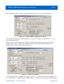
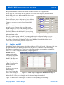


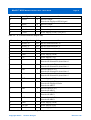


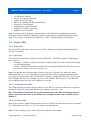

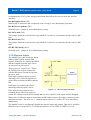

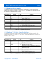
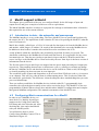

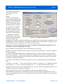


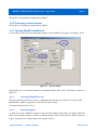
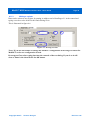

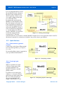
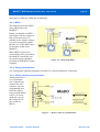


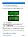

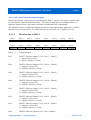

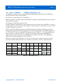
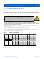


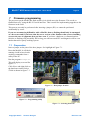


![[U4.81.02] Opérateur CALC_NO](http://vs1.manualzilla.com/store/data/006349976_1-336538590847c8a9ba9a62619c907779-150x150.png)