1
MAX24104
15Gbps Quad Linear Equalizer
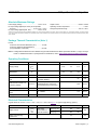
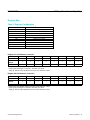
Absolute Maximum Ratings
Power-Supply Voltage...........................................-0.5V to +4.0V
DC Input Voltage Applied (all control pins except SDA
and SCL)............................................... -0.5V to (VCC + 0.3V)
DC Input Voltage Applied (SDA, SCL)..................-0.5V to +4.0V
Output Current................................................... -90mA to +90mA
Operating Junction Temperature...................................... +125ºC
Storage Temperature Range..............................-40ºC to +150°C
Stresses beyond those listed under “Absolute Maximum Ratings” may cause permanent damage to the device. These are stress ratings only, and functional operation of the device at these
or any other conditions beyond those indicated in the operational sections of the specifications is not implied. Exposure to absolute maximum rating conditions for extended periods may affect
device reliability.
Package Thermal Characteristics (Note 1)
FCLGA
Junction-to-Case Thermal Resistance (qJC)................10°C/W
Junction-to-Ambient Thermal Resistance
(qJA) (EIA/JESD51-2 standard)....................................29°C/W
Note 1: Package thermal resistances were obtained using the method described in JEDEC specification JESD51-7, using a four-layer
board. For detailed information on package thermal considerations, refer to www.maximintegrated.com/thermal-tutorial.
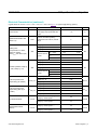
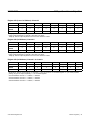
Operating Conditions
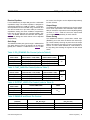
PARAMETER
Supply Voltage
Operating Ambient
Temperature
SYMBOL
MIN
TYP
MAX
UNITS
VCCR,
VCCT,
VCCP
CONDITIONS
2.312
2.5
2.75
V
TA
-40
+25
+85
°C
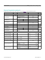
15
Gbps
66
CID
1200
mVP-P
Data Rate
1
Source Data Coding and
CID
Differential Source Diff LowFrequency Voltage
DC balanced NRZ, 8B10B or
Scrambled; PRBS31
VLAUNCH
LF Baseline (without PE)
measured at source; source HF
pre-emphasis swing can be higher
Source Rise/Fall Time
Test source 10% to 90%
Source Common-Mode
Noise
DC - 200MHz
Supply Noise
DC - 1MHz
26
ps
150
50
mVP-P
mVP-P
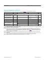
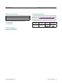
Electrical Characteristics
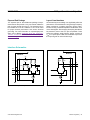
(Typical values are at VCCR = VCCT = VCCP = 2.5V, TA = +25°C. See Figure 1 for typical supply filtering.) (Note 2)
PARAMETER
Supply Current
Supply Current During
Power-Down
www.maximintegrated.com
SYMBOL
ICCR +
ICCT +
ICCP
CONDITIONS
Total supply
current with all 4
channels enabled
MIN
TYP
MAX
TXAx[1:0] = 00
204
275
TXAx[1:0] = 11
250
305
2.0
UNITS
mA
mA
Maxim Integrated │ 2