1
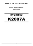
JOHN NEVES & BILL LEWIS
W H E N L I S T E N l N G T O A N FM STATION
in your car, have you ever
noticed the sudden onset of
noise -pops, clicks and humthat lasts for iust a short time?
Maybe you siopped at a traffic
light, heard the interference,
but found that it disappeared
when you drove away-less
than a car length.
This audio annovance could
be caused bv locaf sources of
noise, or it could be caused by
mdtipath-the convergence of
FM signals at your cars antenna
that arrived by taking different
paths from the FM transmitting
antenna. The interference is
commonly called "picket fencing" because it comes and goes
EIiminate muIfipath noise from
FM
drive with this diversity
~ i r ~that
~ iswitches
t
antennasm
FM TRANSMITTER
A ANTENNA
1600 kHz. Thus at 1000 kHz, a n
AM signal has a wavelength of
3 0 0 meters-100
times t h e
length of the FM signal. That's
why AM reception is unaffected
by multipath.
tion was developed in the early
days of radio to counter the
effects of "fading" in shortwave
reception. Shortwave or highfrequency (HF) signals, are capable of traveling thousands of
miles by "bouncing" off ionized
layers 100 kilometers or higher
in ionosphere. They were once
the best method for long-range
communication, a n d fading
could break that communications link.
In those early high-frequency
diversity systems, two separate
a n t e n n a s positioned several
miles apart fed two separate receiver sections. Electronic circuits compared t h e relative
strengths of the two received
signals, and automatically selected the strongest for further
amplification and reception.
The selection was performed by
automatic gain control (AGC).
The output DC level was proportional to the strength of the signal being received.
The same circuitry could improve mobile FM reception, but
two complete receivers would be
required-obviously
impractical and expensive. Moreover,
opening a standard automotive
receiver case to add circuitry
could pose a problem due to
space and power limitations.
The circuit described in this article solves that problem.
Diversity systems
A novel F M system
In the FM reception situation
described, if instead of moving
the car out of the noisy region, a
s e c o n d a n t e n n a were positioned at least 30 inches away
from the first, reception could
be restored. Unfortunately, connecting two antennas simultaneously to a single car radio will
not solve the problem.
The signals from the antenna
in the noisy region would combine with the signals from the
antenna "in-the-clear," and reception would not improve. The
answer to this dilemma is find a
means of switching automatically to the one of two antennas
situated in the most favorable
receiving position.
There is nothing new about
the concept of switching antennas to improve reception. One
method called diversity recep-
In stereo FM broadcasting,
the transmitter encodes left and
right channels as sum and difference signals. The difference
signal, L - R, modulates the 38kilohertz sub-carrier necessary
for decoding the stereo channels at the receiver. It is not
transmitted because of bandwidth restrictions. Instead, the
FM station transmits a pilot
subcarrier at 19 kilohertz, half
the subcarrier frequency. This
pilot phase locks a 38-kilohertz
oscillator in the receiver to decode the stereo signal.
The 19-kHz pilot subcarrier is
within the audio bandwidth,
but its amplitude is so low that
it doesn't disturb the listener.
However, the presence of this pilot subcarrier makes possible
the FM diversity reception system discussed in this article.
FIG. 1-MULTIPATH INTERFERENCE IN FM RECEPTION is caused by signals arriving
out-of-phase at the antenna after traveling over paths of different length.
9
9
Q
20
8-
z
.,o
iii
32
frequency which arrive at your
antenna from the station tuned
in. Radio waves of the same frequency that are out-of-phase, a s
shown in Fig. 2, can cancel each
other in certain locations and
blank out the received signal,
regardless of the FM station's
transmitter power.
However, the effects of multipath are more likely to show up
as partial cancellation of the received signal accompanied by
extraneous noise. If you keep
driving, you will soon pass out
of this "noisy" region. Fluctuations in signal strength might
occur just a quarter wavelength
apart.
T h e FM b r o a d c a s t b a n d
covers t h e radio-frequency
spectrum from 88 to 108 MHz.
Thus at the approximate midb a n d frequency of 100 kHz,
wavelength is 3 meters or about
3% yards. That's why moving
your car only a few feet can take
it out of the noise region.
By contrast, the amplitudemodulated ( A M ) b r o a d c a s t
band, covers the much lower
frequency spectrum of 540 to
T h e FM d i v e r s i t y c i r c u i t
monitors the 19-kHz pilot subcarrier signal.
Steadiness of the reception of
this 19-kHz pilot signal in the
audio portion of the FM transmission is an indication of the
quality of the received signal.
Whenever this signal falls below
a specified threshold value, it
will be lost in background noise.
The threshold establishes the
criterion for switching antennas. In effect, the pilot threshold level f u n c t i o n s i n FM
diversity a s the AGC level functions in HF diversity.
How FM diversity works
A second antenna, installed
on your vehicle as far away from
the original equipment antenna
as practical, provides the second FM signal. Figure 3 is a simplified block diagram of the diversity system.
The cables from both antennas are connected to the electronic antenna switch. The 19kHz pilot signal from the receiver's audio output is passed
through a high-gain bandpass
active filter which attenua.tes
audio programming t h a t i s
much stronger t h a n the pilot
signal. After amplification, the
pilot subcarrier becomes t h e
reference frequency for a phaselocked loop (PLL) circuit. The
output of the PLL locks to the
19-kHz pilot signal and functions a s a subcarrier detector.
When the reference frequency
becomes noisy, the PLL will lose
"lock" and trigger the flip-flop
whose output switches the state
of t h e e l e c t r o n i c a n t e n n a
switch. This action switches
the alternate antenna into the
system while disabling the original antenna.
If that second antenna is positioned for better reception, the
received signal will clear, and
the PLL will again lock to the
subcarrier and hold the switch
in that state until the pilot signal drops out again. If the second antenna does not restore
the pilot signal reception after a
0.1 second delay, the primary
antenna is switched back on.
When the radio is receiving
AM, the absence of a 19-kHz
subcarrier will also reactivate
the primary antenna t h a t is
tuned to the receiver for the best
AM reception.
FM diversity circuit
Refer to schematic diagram
Fig. 4. The audio signal from
the FM receiver appears at connector 54. The two capacitors
Cl1 and C16 in the audio input
section bypass any DC components in the radio output or
overvoltages t h a t could b e
caused by miswiring. Trimmer
potentiometer R22 controls the
input level. The LF347 quad operational amplifier IC3 is a n active filter with a gain of 50 at 19
KHz. It has four sections: a , b, c,
WAVELENGTH
(= 3 METERS FOR FM)
FIG. 2-OUT-OF-PHASE SINE WAVES represent out-of-phase FM signals arriving at a
receiving antenna. They can combine constructively or destructively. An FM signal is
about 3 meters long.
FIG. 3-BLOCK DIAGRAM OF THE FM
DIVERSITY SYSTEM to overcome multipath interference or cancellation.
and d.
The active filter attenuates
the audio so that the LM1800N
phase-locked loop (PLL)IC1 can
lock onto the 19-kHz pilot subcarrier. With 2 millivolts input,
the output level at pin 14 of IC3d is about 100 millivolts. Lightemitting diode LED3 is the level
indicator for IC3-d. Each of the
four 47,000-ohm feedback resistors, R1, R6, R7, and R8,
around the op-amp sections in
IC3 has a 1% tolerance. The
feedback capacitors (reading
from left to right) C6, C4, C19
and C23, and the input capacitors C7, C5, C20, and C21 have
closer 10% tolerances to assure
that the filter will tune in the 19kHz region.
Trimmer potentiometer R21
(in series with resistor R10 at
frequency pin 15 of IC1) sets the
PLL's operating frequency to 19
KHz. Resistor R9 a n d capacitors C2 and C12 form the loop
filter between pins 13 and 14 of
ICl to set the PLL's locking
characteristics including capture time and capture range.
The values shown result in a 1millisecond capture time and 2kHz bandwidth. Bandwidth is
not critical in this circuit because the center frequency is always 19 kHz. However, the wider
the bandwidth, the faster the
capture.
Every time the PLL locks to
the incoming signal, it produces a low-level logic output at
LAMP pin 7 of IC1. When the input signal is lost, pin 7 of IC1
goes h i g h , toggling 7 4 C 7 4
CMOS dual flip-flop IC2-a. Com-
;
2
q
2
c,
8
2,
?
33
plementary output pins 5 and 6
of IC2-a control t h e ONIOFF
states of the two MR901 RF
transistors Q1 and Q2. They are
switched through 33-kilohm resistors R13 and R12, respectively. When Pin 5 of IC2-a is
high, Q1 turns on; when pin 6
id high Q2 turns on.
Transistors Q1 and Q2 are the
active components in two identical broadband, untuned, common-emitter amplifiers. Each
has a gain of about unity in the
AM broadcast band and about 6
dB in the FM band. That 6-dB
gain overcomes cable and connector losses. The low AM gain
prevents AM signal overload.
Transistor Ql's base is con-
nected to antenna input jack 53
for Antenna 1 and transistor
Q2's base is connected to input
jack 5 3 from antenna 2. The
transistor collectors are connected, but only one transistor
can be turned on at a time. As a
result, the circuit works a s a
fast electronic single-pole, double-throw antenna switch.
The load inductance for Q1
and Q2 presents a high impedance at FM frequencies for good
amplification. However, at AM
frequencies this impedance is
low, resulting in low amplification. The output signals at Ql
and Q2 feed back to the working
antenna input jack.
The second half of the CMOS
dual flip-flop IC2, section b, is a
0.1-second timer. If the FM pilot
subcarrier is absent for more
than 0.1 second, 0.1pF capacitor C17, charging through 1megohm resistor R15, toggles
flip-flop IC2-b, forcing pin 8 low.
That low output presets the IC2a flip-flop, biasing Q1 ON and activating antenna 1. This feature
is necessary for AM operation
because antenna 1 is the car's
original equipment or primary
AM antenna.
Flip-flop IC2-a also forces Q1
on for non-stereo FM signals.
The illumination of PILOT LED 3
indicates that the PLL is locked
to the pilot signal. The illumination of ANT 1 LED2 indicates that
antenna 1 is active, and the illumination of ANT 2 LED l indicates that antenna 2 is active.
Building the circuit
Readers are cautioned that
this project is a relatively complex RF circuit that is not recommended for beginners. Successful completion of this project will depend on the builder's
skill and the care taken in circuit assembly and soldering. An
u n d e r s t a n d i n g of how improperly placed and soldered RF
components can cause u n desirable feedback is necessary.
Also, the installation of the circuit calls for current knowledge
of modern automotive radio and
electrical systems.
Even s e a s o n e d b u i l d e r s
should pay particular attention
to details and work cautiously,
especially in the RF adjustment,
FIG. 4--SCHEMATIC DIAGRAM for the FM diversity circuit.
test and installation phases of
the project. Experience in working on automotive electrical and
entertainment systems will be
helpful.
Because the circuit must receive clear high-frequency FM
signals, PC board construction
is recommended. A partial kit,
including an etched and drilled
double-sided PC board with a
ground plane, is available from
the source given i n the Parts
List. Foil patterns are provided
for those who want to make
their own boards.
The ground plane is copper
foil laminated over most of the
component side of the board to
ensure stable RF reception. It
shields the active components
to prevent inadvertent signal radiation, t h u s preventing un-.
wanted oscillations. All of the
electronic components are standard parts, stock items from
mail-order d i s t r i b u t o r s a n d
most electronics retail stores.
All wiring must be a s short as
practical. For example, the leads
of collector inductor L1 must be
short to prevent unwanted oscillations. However, parts placement and wiring in the audio
section is not critical.
Refer to both the schematic
Fig. 4 and the parts placement
diagram Fig. 5. Follow accepted
parts placement practices, and
do all soldering with a fine-tipped soldering pencil rated 30
watts or less, preferably with a
temperature control set to
700°F.The cleanliness of the PC
board and component leads is
important for quality soldering.
Be sure that all solder joints are
smooth and shiny; cold solder
joints are usually dull gray and
irregular.
Use sockets for the all ICs,
and observe the location of pin 1
when installing all sockets.
Mount the eight axial-leaded
0.001 pF polyester capacitors
C4 to C7, C19 to 21, and C23,
the 390 pF C3 and the 0.047 FF
C8 vertically. With needle-nose
2
$
G
-8
m,rr
$.
G:
5
-Z
35
FIG. !+PARTS
g
2
g
z
.-%
E
36
PLACEMENT DIAGRAM for the FM diversity circuit.
pliers, grasp a lead at one end of
the capacitor close to the body
and bend the lead back 180" to
form closely spaced radial leads.
Find the cathode band on diode Dl and insert the lead on
that end in the cathode location
shown in placement diagram
Fig. 5. The three light-emitting
diodes LEDs 1, 2, and 3 in the
prototype were in T-1-style radial-leaded packages. The longer
lead on these LEDs is the anode
lead (arrowhead side of the symbol), and the short lead identifies the cathode lead (bar in the
symbol).
Insert and solder the three
LEDs w i t h o u t c u t t i n g t h e i r
leads. Mount t h e m s o they
stand off the board about 1%inches so the leads can be bent
to insert the reflectors into the
pre-drilled holes in the case
after the completed board is
mounted to the lower case half.
Transistors Q1 and Q2 have
flat leads to minimize inductance. Position the transistors
carefully on the board before
soldering them. Caution: The
t r a n s i s t o r s ' orientation a n d
spacing with respect to each
other and the other RF components is critical.
Install the two polarized capacitors, tantalum dipped, radial capacitor C24 and aluminum electrolytic C25, according
to the polarity marks shown on
Fig. 5. Caution: Be sure the
minus ( - ) side of both capacitors is connected to ground; a n
improper connection can destroy the capacitor.
Integrated circuit IC2 must
be a CMOS B 74C74 because the
power source is 12volts. Comparable parts in the HC a n d
HCT CMOS logic families are
rated for only 5 volts.
After inserting and soldering
all of the components on the PC
board, cut,insert and solder the
color-coded wires for the casemounted connector jacks. The
wires should all be cut about 3
inches long from No. 22 or 24
AWG insulated stranded hooku p wire. Use red wire to indicate
positive ( + ) and black to indicate negative ( - 1 ground for
power jack 55. Use any other
color for the audio input signal
to jack 54, but use black for the
ground connection there also.
Insert and solder lengths of
twisted black and red wire for
the R F connector jacks J1, 5 2
and 53 with the red wires for the
antenna and radio input signals and black wires for ground.
+
Packaging the circuit
The plastic enclosure specified in the Parts List is recommended because the circuit
board described in this article is
sized to fit snugly in it. Refer to
Fig. 6 for the proper orientation
of jacks with respect to the circuit board, and mark the cen-
ters of holes to be drilled for the
fivejacks J 1 to 5 5 on the ends of
the lower half case using the
hole-forming t e m p l a t e s i n cluded in this article. Exact hole
diameter and shape should be
determined by measuring the
actual jacks.
Mark the positions of the
holes for the three LEDs in the
side wall of the case with the aid
of the template and a s shown in
Fig. 6. Drill the LED holes with a
drill size that will permit the
LEDs to be press-fit in the side
of the case so that no adhesive
will be needed.
Clean the completed circuit
board with cotton swabs dipped
in cleaning fluids intended for
that purpose. Insert the board
in the lower half of the case a s
shown in Fig. 6, and fasten it to
the two internal sidebars of the
case with small sheet-metal
screws.
Next, install and fasten the
three RF connector jacks, J1,
52, and 53, power jack 55, and
audio input jack J6. Solder the
wires from the circuit board to
the lugs on the jacks. Wire jacks
J l , J 2 , and 53 with the twisted
pairs. They should be trimmed
as short as possible before they
are soldered to the connectors.
Solder the black wires for the
ground connections to the jack
shells and the red wires for the
signal paths from the antennas
and radio. (It might be necessary to remove s o m e metal
plating from the jack shells with
emery cloth or a file to obtain a
secure solder joint.)
Carefully b e n d b o t h LED
leads together so that the reflect o r body c a n be p r e s s - f i t
through the previously drilled
holes on the side of the case.
Double check the completed
assembly carefully A magnifying glass will be helpful. Check
for any incorrectly inserted
components, solder bridges, or
cold solder joints.
Identify all the jacks a n d
LEDs on the outside of the case
with a waterproof pen or dry
transfer lettering. Label LED3
a s PILOT, LED1 a s ANT 2 a n d
LED2 a s ANT 1 . Label J 1 as RADIO
INPUT, 5 2 a s ANT 1 a n d 53 a s
ANT 2. Label 54 as AUDIO INPUT
and 5 5 as
12 V." Cover the
"+
labels with transparent tape or
coat them with nail lacquer. Figure 8 is a photo of the author's
assembled prototype.
Testing and tuning
Before applying power to the
board, measure the resistance
between the positive power supply connection and ground. It
should be 3000 ohms or higher,
a f t e r t h e filter c a p a c i t o r
charges. If it is lower, recheck
the circuit for shorts or incorrectly installed ICs.
The power source required to
perform these tests can be a 12volt nickel-cadmium battery, a
12-voltlead-acid batten3 or a 12volt DC wall-outlet adapter. If
you use a n adapter, be sure it
has a standard 2.1 millimeter
diameter axial pin in the plug.
Read the label on the adapter to
be sure that the positive ( + )
conductor of the plug is the axial lead and the negative ( - )
conductor is the shell.
Put a %-ampere fuse in series
with the power supply to pre-
.
2718
INCHES
vent damage to the circuit if
there are undetected shorts. An
FM radio or tuner with an earphone or speaker plug connector is also required. The test
setup shown in Fig. 7 emulates
the wiring circuitry of a n automobile installation.
Tune the FM receiver to a stereo FM station. (The stereo indicator should be illuminated).
Set the volume control from one
quarter to one third of its maximum angle. Then connect the
audio input of the diversity circuit to the FM radio's headphone or speaker.
Apply power to the system.
With a plastic alignment tool or
small screwdriver, adjust audio
input-level potentiometer R22
to mid-position. Then adjust
PLL frequency-set potentiometer R21 slowly until LED3 is illiminated. After this adjustm e n t , LED3 will t r a c k t h e
radio's stereo indicator to verify
the presence of the stereo pilot
subcarrier signal with different
thresholds.
*
.
The radio indicator works
with all stereo stations, and the
diversity circuit depends on the
audio volume and the setting of
input-level potentiometer R22.
Either LEDl or LED2 should be
on. Turn down the volume control on the FM radio until LED 3
e x t i n g u i s h e s . Observe t h e
LEDl a n d LED2 p a i r : They
should alternate between on
and off each time LED3 goes
out.
Turn the volume-control knob
u p a n d down to check t h e
switching action. ' h r n the volume down once or twice s o
LED2 stays on, then keep the
volume low. After 0.1 second,
LEDl will light and LED2 will go
off. That indicates the one-second timer is working.
Connect the RADIO INPUT cable
from J 1 to the FM radio's antenn a input jack. If the existing FM
radio receiver does not have external antenna connections, retract its antenna completely,
and convert it to the input connection with wires connected by
171a INCHES
-.
FOIL PATTERN FOR THE COMPONENT SlDE OF THE PC BOARD. FOIL PATTERN FOR THE SOLDER SIDE OF THE PC BOARD.
37
two alligator clips. 'l'he second
connection is for ground, the
outer part of the cable or jack.
Unless t h i s connection is
made with a coaxial cable, the
antenna will not function correctly, and the test will be invalid. Light-emitting diode LED2
will be illuminated after the onesecond timeout. Antenna 1 will
be the active antenna. Conversely, LED1 will indicate that
antenna 2 is active.
Connect two test antenna cables to their jacks in the diversity circuit. One of these could
be the extra antenna you purchased for installation in your
car. A three-foot length of insulated hookup wire stretched vertically will serve as the second
antenna, Regardless of what
you use as an antenna, it must
make contact with the axial
conductor of the connector. A
banana plug can serve a s a
makeshift connector.
7hne in an FM station, check
to see which LED is illuminated, and then disconnect the
related antenna. This step will
permit the circuit to switch to
the alternative antenna, a s
shown by LED illumination. If
the signal from the FM station
selected is strong, switching action can be prevented if the antenna connections are not well
shielded.
Choose a different station
and repeat the test. Then repeat
the test for the other antenna.
Adjust the volume control to
command antenna switching.
When the desired LED turns on,
remove the corresponding antenna, and the ability of the
LEDs to turn on and off should
be restored.
This test does not reproduce
actual circuit operation because it is not possible to simulate, at a fixed location, the FM
radio reception conditions to
which your vehicle is exposed.
In a car installation, the proper
FIG.&ASSEMBLY AND WIRING OF CASE-MOUNTED components.
connectors and coaxial cables
form well shielded connections
without RF leakage. Nevertheless, this bench test can demonstrate that the RF switching is
functional.
If you can perform this test
with an actual auto radio receiver and the coaxial cables
recommended in the Parts List,
the test will still be a realistic
approximation of a n a u t o motive installation.
Installation in a car
Refer again to Fig. 7, and install the second antenna on
your car. The greater the separation between the primary and
secondary antennas, the more
effective will be the diversity circuit's operation. If, for any reason, you do not want to install a
second full-size antenna, you
can purchase a flat antenna
that adheres to the windshield
glass.
The cable from the originally
installed antenna probably will
not reach the diversity circuit
unless the antenna was installed at the rear of the car. In
that case, the secondary installed antenna must be located
at the front of the car. The antenna extension cables listed in
the Parts List might be required.
Alternatively, you can make
your own extension cable from
low-loss coaxial cable terminated by male a n d female
Motorola-type connectors.
Another possibility is an automotive M F M antenna whose
design is based on that for a surface-mount cellular telephone
a n t e n n a . A source for t h e
03CH7516N antenna with 17
feet of cable is given in the Parts
List. However, an extension cable will not be needed for most
cars.
A horizontal antenna such as
the windshield type mentioned
will provide polarization diversity because FM broadcast stations transmit both vertically
a n d horizontally polarized
waves. This will be an advantage even if the two antennas
are not very far apart.
Access to the radio's electrical
connections in most cars can be
gained by removing the front
panel of the radio, and pulling it
out to expose the antenna and
speaker connections. Consult
the maintenance manual for
your car radio for details on how
to remove the radio without
damaging it.
The latest model car radios
have RCA audio o u t p u t connectors. Those will will make it
easy to provide the audio for the
diversity circuit.
Alternatively, the audio signal
source will be the radio's speaker output terminals. Any of the
stereo outputs will provide the
signal depending, of course, on
the stereo BALANCE control setting. Identify all of the speakers'
terminals and wiring. Consult
your user's manual or read the
labels on the wires.
Radio manufacturers do not
all follow a uniform wiring color
code, so the functions of the
wires cannot be determined
reliably from their colors. However, several leading manufacturers have agreed on green and
gray for the left and right speakers, respectively, and black for
common or ground. The ground
(or low side) goes to the ground
side of the audio input jack of
the diversity circuit. Only one
audio source is required for the
operation of this circuit.
Caution: Do not connect the
unit to the output of a n external
power booster.
Unfortunately, you have no
g u a r a n t e e t h a t your radio's
power amplifier will have sufficient bandwidth to allow the 19kHz subcarrier to pass. Tap the
audio from the input cable to
the power amplifier. If resistive
"faders" have been installed, tap
the audio signal upstream of
them.
Any connections spliced to
the speaker wires must be insulated with quality electric tape
so they will not be shorted to
ground. Connect the original
equipment car antenna to the
antenna input jack ANT 1 . Then
connect the second antenna to
input jack ANT 2. Connect the
diversity circuit to the FM receiver with an extension cable
terminated by two male plugs,
one end plugged into the RADIO
INPUT jack.
The required 12-volt power
FIG. 7-THE FM DIVERSITY SYSTEM installed in an automobile with one antenna, a
radio and speakers.
can be obtained from a fused
cigarette lighter adapter cable.
Install a Y4- or ?hampere fuse in
the fuse holder to protect the
diversity circuit. However, if you
want a more permanent connection, you can make one with
a n in-line fused cable for the
power connection to the spare
lugs usually available in the
car's fuse box. See the Parts
List.
Turn on the receiver and plug
in the adapter. Tune to a stereo
station, and set the receiver for
normal listening while driving.
Readjust input-level trimmer
potentiometer R22 for this normal audio volume setting in the
c a r u n t i l LED3 remains on
without blinking. Set the tone
or treble control to at least onequarter of a turn towards maximum. If this is not done, the 19
kHz pilot subcarrier signal will
'
be too low. If LED3 doesn't light
up, readjust the PLL frequencyset trimmer potentiometer R21
until it does.
Verify that LEDl and LED2
change state each time you
lower the volume. Then change
stations. That also will control
the LEDl to LED2 switching.
Input-level trimmer potentiometer R22 controls switching
sensitivity If it is set too low,
LED3 will not light. Set it so
LED3 r e m a i n s o n w i t h o u t
blinking when a clear stereo station is being received. Trimmer
R21 must be set in the middle of
its "lock" range, the span between the two points in wiper
rotation where LED3 turns on
and off.
Check the 19-kHz pilot subcarrier level at the audio output
of a receiver with a high-Q bandcontinued on page 85
consumer is happy with his Hitachi
rice cooker, vacuum cleaner, or
washing machine, he is likely to seriously consider a Hitachi audio
component. In other words, the
brand names of audio-equipment
manufacturers are a familiar part of
Japanese life. Large Japanese industrial companies also encourage
their employees with various savings plans and discount arrangements to invest in their "house
brand" audio equipment. The result
of all this has been the development
of a large number of hard-core audiophiles plus a higher level of interest on the part of the general public.
CD costs
Unlike the situation with conventional record players where, by and
large, the more you paid the better
they got, even the cheapest CD
players provide excellent quality.
Player costs have probably come
down about as low as they are going
to get. I've seen units advertised for
slightly over $100.
I still don't understand the economics of player pricing. They are
not like memory ICs whose cost per
unit falls radically with time and
sales because the inherent "parts"
cost is insignificant to start with. CD
players are crammed with precisionmade mechanical parts that, it
seems to me, are going to continue
to keep the prices from going any
lower. I'm grateful-and so should
the rest of you be-that the prices
of CD players have fallen as far
down as they have.
Disc prices, on the other hand,
have not fallen significantly from the
1983 initial introductions at $15 to
$20. Interestingly, during a 1981 report on a visit to Denon's Tokyo recording studio, I quoted an engineer
who said that, unlike the situation
with CD players, the cost of the disc
itself would not come down substantially with time. However, considering the effects of inflation and
the significant rise in the yen with
respect to the dollar, CD's are now
something of a bargain. At least, if
sales figures are an accurate indication, the music listening public
seems to think so.
In any case, Happy Tenth Birthday
to the Digital Compact Disc-and
R
long may it rotate.
I
pass filter and an oscilloscope.
Five millivolts of the pilot subcarrier will ensure proper system operation.
Temporarily fasten the diversity circuit to the automobile
dashboard with duct tape, but
put a cardboard hood over the
LED lamps so that they can be
seen more easily i n daylight.
Tmke the system for a test drive.
Ask a passenger to check the
switching action by observing
the three LEDs a s you drive.
When you are satisfied that
t h e diversity circuit works,
m ou n t i t in u n d e r t h e
dashboard where it cannot be
seen by passengers in the front
seat, but where you can see the
illuminated LEDs by ducking
your head down close to the
seat. Because of the wide variations in the size and shape of
the space available under auto-
mobile dashboards and the limited space available for mounting a n electronics case, universal mounting directions cannot
be given. After selecting a n appropriate location where the input and output wires and cables
are free of stress, you can clamp
the package in position with a n
adhesive-backed plastic clamp,
a strap that you fashion from
plastic or light metal, or even
duct tape.
Application precautions
It is possible that the diversity
circuit will not work on automotive radio receivers that are
more than about 20 years old
because of their restricted audio
bandwidth. Nevertheless, the
prototype was tested on several
different car radios with differing ages, and it worked satisfactorily on all of them. The circuit
will work with most late-model
stereo receivers because they
typically have a s much a s 20kHz audio bandwidth.
s2
1
SELF-PACED,
PROFESSIONAL-LEVELHOME STUDY COURSE
This easy-to-follow, step-by-step course teaches you high-profit
PC reparis, troubleshooting, servicing, upgrading, and installation.
Increase vour value-and your salary-as a computer expert
where your work. Or make better money in your
own business providing a much-needed service.
You need no high-tech electronics, no expensive
fancy workshop. Over 90% of
PC repairs involve simple,
mechanical procedures or
parts replacement using
ordinary hand tools.
Professional-level,oneon-one instruction. Study
r the guidance of
seasoned PC experts.
Free literature:
call 800-223-4542
Age
-
Phone (
State
ZIP
The School of PC Repair
-
6065 Roswell Rd , Dept JM342,Atlanta, GA 30328
6-
CIRCLE 178 ON FREE INFORMATION CARD
I
I
Id 85