1
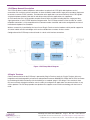
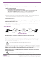
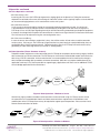
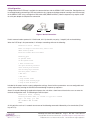
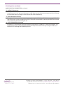
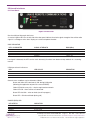
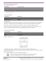
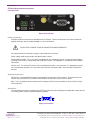
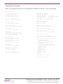
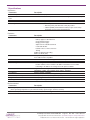
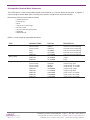
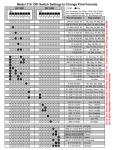
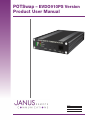
POTSwap – EVDO910PS Version
Product User Manual
Bulletin
Revision
Date
JA16-CDMA-UM
P03
21 Oct 2014
TABLE OF CONTENTS
TABLE OF CONTENTS, LIST OF FIGURES and DISCLAIMER........................................................................................... 2-3
1. POTSwap General Description .................................................................................................................................. 4
2. Plug-In Terminals......................................................................................................................................................... 4
3. Operation.................................................................................................................................................................. 5-6
3.1 Set-up
3.2 Voice Operation
3.2.1 Placing Calls
Manual Telephones
Automated Dialers
3.2.2 Receiving Calls
3.3.3 Call Disconnect
3.3 Data Operation
4. Configuration.......................................................................................................................................................... 7-10
5. External Interface ................................................................................................................................................ 11-14
5.1 Front Panel:
Received Signal Strength Indicator
LED Operational indicators:
POWER (RED) LED
CELLULAR (YELLOW) LED
STATUS (GREEN) LED
PUSH BUTTONS
PHONE – FXS Connector
5.2 Rear Panel:
Power connectors
Antenna connectors
Serial Port
6. Provisioning.......................................................................................................................................................... 14-15
7. Specifications............................................................................................................................................................ 16
8. Compatible Terminal Block Connectors................................................................................................................... 17
9. Ordering Information................................................................................................................................................. 18
10. Accessories............................................................................................................................................................... 18
11. References................................................................................................................................................................. 18
Revision History......................................................................................................................................................... 19
POTSwap User Guide JA16-CDMA-UM
Page 2
Rev: P03
Date: 10/21/14
© Copyright 2014 Janus Remote Communications Specifications subject to change without notice
All Rights Reserved See website for latest revision.
Not intended for life support applications.
TABLE OF CONTENTS continued
List of Figures
Figure 1. POTSwap Block Diagram
Figure 2. Voice Operation
Figure 3. Data Operation – Modem to Server
Figure 4. Data Operation – Modem to Modem
Figure 5. Serial Connection
Figure 6. Front Panel
Figure 7. RJ11 Jack
Figure 8. Rear Panel
Figure 9. Serial Port
DISCLAIMER
The information contained in this document is the proprietary information of Connor-Winfield Corporation and its affiliates (Janus Remote Communication). The contents are confidential and any disclosure to
persons other than the officers, employees, agents or subcontractors of the owner or licensee of this document, without the prior written consent of Connor-Winfield, is strictly prohibited. Connor-Winfield
makes every effort to ensure the quality of the information it makes available. Notwithstanding the foregoing, Connor-Winfield does not make any warranty as to the information contained herein, and does
not accept any liability for any injury, loss or damage of any kind incurred by use of or reliance upon the information. Connor-Winfield disclaims any and all responsibility for the application of the devices
characterized in this document, and notes that the application of the device must comply with the safety standards of the applicable country, and where applicable, with the relevant wiring rules. ConnorWinfield reserves the right to make modifications, additions and deletions to this document due to typographical errors, inaccurate information, or improvements to programs and/or equipment at any time
and without notice. Such changes will, nevertheless be incorporated into new editions of this application note.
All rights reserved 2012 Connor-Winfield Corporation
POTSwap User Guide JA16-CDMA-UM
Page 3
Rev: P03
Date: 10/21/14
© Copyright 2014 Janus Remote Communications Specifications subject to change without notice
All Rights Reserved See website for latest revision.
Not intended for life support applications.
1 POTSwap General Description
The POTSwap allows landline telephones and modems to replace their POTS (plain old telephone service)
connection with a wireless cellular connection. An internal landline modem allows legacy dial-up modem equipment
to connect to remote TCP/IP networks. Fixed location voice applications can connect directly to the PSTN (public
switched telephone network). Both dial-in and dial-out data and voice applications are supported.
An FXS connection (RJ11 jack) provides complete Central Office emulation including dial tone, ringing and busy
signal generation as well as DTMF detection and generation. The POTSwap emulates all the functions of a wired
telephone connection, is fully compatible with all common modem standards and can be configured to emulate all
international telephone line standards.
Wireless connectivity is provided by the Janus line of Plug-In Terminus terminal modems which provide support for
all current mobile network technologies with service available from numerous wireless carriers.
Configuration of the POTSwap can be achieved via a local serial interface connection.
Figure 1 POTSwap Block Diagram
2 Plug-In Terminus
Cellular communication for the POTSwap is powered by Plug-In Terminus terminals. Plug-In Terminus offer easy
integration and interchangeability of communication protocols between GSM/GPRS, CDMA, UMTS, EVDO and more
by combining full M2M functionality with the flexibility of a standard “plug-in” DIP design. These terminals share
the same mechanical footprint and offer users the ability to configure their applications for communications via any
cellular protocol. The POTSwap provides one platform that supports current cellular technology with the future in
mind.
POTSwap User Guide JA16-CDMA-UM
Page 4
Rev: P03
Date: 10/21/14
© Copyright 2014 Janus Remote Communications Specifications subject to change without notice
All Rights Reserved See website for latest revision.
Not intended for life support applications.
3 Operation
3.1 Set-Up:
Operating the POTSwap with voice (telephone) or data (modem) equipment can be achieved through the
following steps:
1. Gather the required equipment:
• POTSwap (with included Plug-In Terminus terminal module)
• Power Supply - This can be hard-wired from a user supplied power source via the terminal block header
(See section 8 - Compatible Terminal Block Connectors) or using the optional wall transformer
(See section 10 - Accessories).
• Cellular antenna - An optional cellular antenna is available (See section 10 - Accessories).
2. Connect a cellular antenna to the SMA connector labeled ‘CELLULAR’. This can be a local antenna or a
remote antenna connected by a coaxial cable. (See section 10 Accessories section.)
3. Connect power to the unit.
Once powered, the unit should show a connection to the cellular carrier within a minute. This will be indicated by
a rapidly flashing GREEN ‘STATUS’ LED, a blinking ‘CELLULAR’ LED, and a steady signal strength indication on
the Received Signal Strength LED stack.
4. The DE910PS model of the POTSwap must have a provisioned cellular radio. If the unit has not been
provisioned yet, see section 6 - Provisioning.
3.2 Voice Operation
MOBILE
NETWORK
PSTN
CELLULAR
TELEPHONE
POTSwap
TELEPHONE
VOICE
Figure 2 Voice Operation
Voice operation requires a standard voice telephone device to be connected to the POTSwap.
3.2.1 Placing calls:
When the connected telephone device is taken off hook, the POTSwap will present an audio dial tone signal.
Dialing can proceed, and must consist of a ten digit phone number that includes the area code. Eleven digit
dialing is accepted when the first digit is a ‘1’.
The POTSwap CANNOT be used to dial 3-digit numbers such as 911.
A dialing timeout will occur if no initial digit is entered within the period defined by the Dialing Tone Timeout or if
the period between entered digits exceeds the Dialing Digit Timeout. The Dialing Tone Timeout and Dialing Digit
Timeout periods are user configurable. If the dialing timeout periods are exceeded, the POTSwap will terminate
the dialing attempt by generating an Open Switching Interval. See section 4 - Configuration.
Telephone devices that automatically take the phone off-hook and place a call to a fixed telephone number are
compatible with the POTSwap. Dialing digits should not be sent faster than 100 ms per digit, with a minimum
DTMF tone duration of 45 ms.
The POTSwap is compatible with DTMF dialing only. Pulse dialing will not work.
POTSwap User Guide JA16-CDMA-UM
Page 5
Rev: P03
Date: 10/21/14
© Copyright 2014 Janus Remote Communications Specifications subject to change without notice
All Rights Reserved See website for latest revision.
Not intended for life support applications.
3 Operation continued
3.2 Voice Operation continued
3.2.2 Receiving calls:
Incoming calls will cause the POTSwap to generate a ringing signal on the phone line. Taking the connected
telephone line off-hook will answer the incoming call. Note that cellular carriers typically impose a 30 second limit
on unanswered ringing before a call is transferred to a voice mail system.
3.2.3 Call Disconnect:
A call can always be terminated by placing the connected telephone equipment on-hook. If a cellular call
is terminated on the carrier side (the result of a connected party ending the call or due to loss of signal) the
POTSwap will use an OSI (Open Signaling Interval) to aid in disconnecting automated type telephone equipment.
It removes the voltage from the phone line connection for a short time to signal that the call has been terminated.
The OSI interval can be adjusted using the user configuration menu.
3.2.4 Unconnected Busy:
In some instances when dialing a number that is busy, the cellular carriers will not make an audio connection
to a busy tone. If this occurs, the POTSwap will generate the busy tone locally for a period defined by the user
configurable Busy Dwell Timeout parameter. Following the busy tone, the POTSwap will terminate the call by
generating an Open Switching Interval (see section 4 - Configuration).
3.3 Data Operation (Future firmware feature):
Telephone modem equipment can be connected to the POTSwap for the purpose of converting a legacy landline
data connection to a cellular connection. The POTSwap can simulate the remote dialed modem and transfer the
data using a TCP/IP connection. At the remote location, an accommodation has to be made for the change in
data transport technology (dial-up modem to internet connection). While this may require modifications to the
application software, it may also be possible to support legacy applications with the use of an additional TCP/IP
to serial bridge application on the remote host.
SERVER
MOBILE
NETWORK
INTERNET
CELLULAR
DATA
MODEM
POTSwap
PC
Figure 3 Data Operation – Modem to Server
Alternatively, legacy modem to modem communications can be achieved using a POTSwap at each end of
the connection as illustrated below. Note that all data communications requirements will be different, and
modifications to the POTSwap firmware may be required to support specific operations. Please contact Janus
Remote Communications for details.
CELLULAR
DATA
MODEM
POTSwap
MOBILE
NETWORKS
& INTERNET
CELLULAR
DATA
MODEM
POTSwap
Figure 4 Data Operation – Modem to Modem
POTSwap User Guide JA16-CDMA-UM
Page 6
Rev: P03
Date: 10/21/14
© Copyright 2014 Janus Remote Communications Specifications subject to change without notice
All Rights Reserved See website for latest revision.
Not intended for life support applications.
4 Configuration
Configuration of the POTSwap is available via communications with the SERIAL PORT connection. Configuration can
be accomplished by connecting a DTE terminal device (e.g. laptop or desktop computer running a terminal emulator)
to the SERIAL PORT using a straight-thru DB9 serial cable (DB9-M to DB9-F). Newer computers may require a USB
to serial port adaptor to complete the connection.
Figure 5 Serial Connection
Default communications protocol is 115200 baud, 8-N-1 (8 data bits, no parity, 1 stop bit) with no handshaking.
When the POTSwap is first powered on, it will output something similar to the following:
WireLine II Board - POTSwap
Audio via digital interface DVI, PCM to SLIC
HE910 Power-Up Mode
Board has SiLabs Wire Line Modem
WireLine_Open
25 Speaker Level
25 Microphone Level
1 Echo Cancellation
900 Open Switching Interval
30000 Dialing Tone Timeout
6000 Dialing Digit Timeout
6000 Busy Dwell Timeout
2 ADC Gain
4 DAC Gain
2 Loop Current Limit
0 Loop Closure Sensing Type
8 Loop Closure Threshold
Included in this output are the current configuration settings. Several of these parameters are user configurable and
can be adjusted by entering the CONFIG command during the power-up sequence.
About 15 seconds following the application of power, the unit offers a short interval wherein the user can enter the
terminal configuration menu. The following text will be output:
WireLine II Board - POTSwap
Entering Terminal Mode, 10 seconds to type first command
Type ? for help, Q to exit
FW: HH:MM:SS MTH DY YEAR
READY
At this point the user has 10 seconds to enter one of the following commands followed by a line termination (‘Enter’
key on PC’s):
POTSwap User Guide JA16-CDMA-UM
Page 7
Rev: P03
Date: 10/21/14
© Copyright 2014 Janus Remote Communications Specifications subject to change without notice
All Rights Reserved See website for latest revision.
Not intended for life support applications.
4 Configuration continued
TERMINAL MENU COMMANDS
COMMAND
FUNCTION
?, H Outputs the current menu options.
Q, QUIT
Exits the menu and causes the POTSwap to proceed with the normal operation.
DEBUG xx
Factory use only
DUMP Adr Len
Factory use only
XMODEM
Download upgrade binary
REBOOT
Restart Application
CONFIG Configure Settings
PROVISION
IDENTIFY
Display Cellular MEID (Mobile Equipment IDentifier) and phone number
These commands are NOT case sensitive. Terminal menu commands operate as follows:
?, H: Entering a ‘?’ or ‘H’ character will output the Terminal menu command menu again. It can be useful if the
menu has scrolled off of a screen.
Q ,QUIT: Entering ‘Q’ or ‘QUIT’ will exit the DEBUG menu and continue with the normal start-up and operation of
the POTSwap.
DEBUG xx: DO NOT USE - Factory use only.
DUMP Adr Len: DO NOT USE - Factory use only.
XMODEM: Used for firmware upgrades.
REBOOT: Entering ‘REBOOT’ will restart the POTSwap, similar to pressing the RESET button.
CONFIG: Entering ’CONFIG’ will cause the configuration menu to be output:
Janus Remote Communications - WireLine II Board - POTSwap Configuration
=======================================================================
Microphone Level
Speaker Level
Echo Cancellation
Open Switching Interval
Dialing Tone Timeout
Dialing Digit Timeout
Busy Dwell Timeout
[25] 0-31
[25] 0-31
[1] 0-1
[900 ] 100-1200 ms
[30000] 500-60000 ms
[6000 ] 250-15000 ms
[6000 ] 1000-30000 ms
SLIC ADC Gain
SLIC DAC Gain
[2] 0-8
[4] 0-8
Loop Closure Sense Type [0] 0-1
Loop Closure Threshold [8 ] 0-63
Press M=Modify, D=Defaults, X=Exit and Save, Q=Quit and Discard
The configuration menu lists the name of the parameter, the current setting (in brackets), and the range or values of
settings available. These settings may vary depending on the model of Plug-In Terminus terminal used in the POTSwap.
Following the list of parameters are options for changing the configuration settings or leaving this menu: M, D, X, and
Q. These single character command options can be entered in upper or lower case, and no enter key is required.
POTSwap User Guide JA16-CDMA-UM
Page 8
Rev: P03
Date: 10/21/14
© Copyright 2014 Janus Remote Communications Specifications subject to change without notice
All Rights Reserved See website for latest revision.
Not intended for life support applications.
4 Configuration continued
CONFIGURATION COMMANDS
COMMAND
FUNCTION
M – MODIFY
D – DEFAULTS
X – EXIT AND SAVE
Q – QUIT AND DISCARD CHANGES
Enter the parameter modification menu.
Set all parameters to their default (factory) value.
Save changes and exit the configuration menu.
Discard changes and exit the configuration menu.
M – MODIFY Commands:
Entering an ‘M‘ command will cause the current setting for each parameter to be output, and allows changing the
parameter setting. Currently, the following parameters can be modified:
CONFIGURATION PARAMETERS
PARAMETER
DEFAULT
RANGE
FUNCTION
Microphone Level 4
0-7
Sets the outbound audio gain
Speaker Level
7
0-14
Sets the inbound audio gain
Echo Cancellation 1
0-1
Enables the Echo Cancellation feature
0 = Echo Cancellation disabled
1 = Echo Cancellation enabled
Open Switching Interval
900
0-1200
Sets the period that the battery voltage is removed from the
(milliseconds)
telephone line following the termination of a call from the
carrier side, a dialing timeout, or a locally generated busy
tone. (AKA Kewlstart.)
Dialing Tone Timeout†
30000
500-60000
Sets time limit for first dialing digit to be entered following (milliseconds)
off-hook. Exceeding the time limit will cause Open Switching
Interval to be generated.
Dialing Digit Timeout†
6000
250-15000
Sets time limit for time between entering dialing digits.
(milliseconds)
Exceeding the time limit will cause Open Switching Interval to
be generated.
Busy Dwell Timeout†
6000
1000-30000
Sets length of time a busy tone is generated locally on calls
(milliseconds)
where the cellular carrier does not provide an audio connetion
to a busy tone. The Open Switching Interval will be generated
following the busy tone.
SLIC ADC Gain
2
0-8
Sets outbound audio gain during the initial outbound DTMF
dialing. Corrects for distortion using some auto dialers.
SLIC DAC Gain
4
0-8
Sets inbound audio gain. Should be set at 4.
Loop Closure Sensing Type**
0
0-1
Sets loop closure (off-hook) sensing type.
0 = current sensing
1 = voltage sensing
Use 0 (current sensing) for applications using ringer loads of
REN=1 or less. Use 1 (voltage sensing) for ringer loads of
REN>1, up to REN=5.
Loop Closure Threshold**
8
0-63
Sets loop closure (off-hook) sensing threshold.
Current sensing: 1.27 ma/unit (e.g. ‘8’=10.26 mA)
Voltage Sensing: 1.45 V/unit (e.g. ‘10’=14.50 V)
Recommended settings:
REN<=1: Current sensing; threshold=8 [default]
For REN>1 to REN=5: Voltage sensing; threshold=10
* 12 on firmware versions 131011 and lower
** available on firmware versions 140207 and higher
† available on firmware versions 140725 and higher
POTSwap User Guide JA16-CDMA-UM
Page 9
Rev: P03
Date: 10/21/14
© Copyright 2014 Janus Remote Communications Specifications subject to change without notice
All Rights Reserved See website for latest revision.
Not intended for life support applications.
4 Configuration continued
CONFIGURATION PARAMETERS continued
D – DEFAULTS Command:
Entering the ‘D’ command will change all of the settings back to the factory defaults. These settings will not be
saved unless the ‘X’ Exit and Save command is issued. Older versions of firmware will request that the POTSwap
be restarted to effect the changes; current versions will restart automatically.
X – EXIT AND SAVE Command:
Entering the ‘X’ command will save any changes made using the ’M’ Modify or ‘D’ Defaults commands. This will
also exit the menu system and requires that the POTSwap be restarted either by pressing the RESET push button
or by un-powering and re-powering the unit.
Q – QUIT AND DISCARD Command:
Entering the ‘Q’ command will discard any changes made using the ’M’ Modify or ‘D’ Defaults commands. This
will also exit the menu system and requires that the POTSwap be restarted either by pressing the RESET push
button or by un-powering and re-powering the unit.
POTSwap User Guide JA16-CDMA-UM
Page 10
Rev: P03
Date: 10/21/14
© Copyright 2014 Janus Remote Communications Specifications subject to change without notice
All Rights Reserved See website for latest revision.
Not intended for life support applications.
5 External Interfaces
5.1 Front Panel
Figure 6 Front Panel
Received Signal Strength Indicator
A stack of 4 green LED’s on the left side of the front panel indicate the relative signal strength of the cellular radio
signal. It is analogous to the ‘bars’ display on a cellular telephone handset.
RSSI INDICATOR
LED’s ILLIMINATED
SIGNAL STRENGTH
RSSI (dBm)
4
3
2
1
Excellent
Good
OK
Marginal
-73 or better
-83 to -74
-93 to -84
-109 to -94
If no signal is detected, the LED’s on the stack alternately illuminate from bottom to top and back in a ‘scanning’
manner.
LED Operational indicators
LED
LED COLOR
POWER
CELLULAR
STATUS
Red
Power status
YellowCellular radio status
Green
System status
INDICATION
General status conditions can be inferred as follows:
Green and Yellow LED continuously ON: during initialization
(following the application of power or a manual RESET).
Yellow LED blinks every 2.5s – wireless registered on network.
Yellow LED ON - when cellular call connected.
Green LED fast blink - when on hook (no call in progress)
Green LED - ON when off hook (during call)
POWER (RED) LED
LED STATUS
INDICATION
ON
OFF
Blinking
System is powered
System has no power
System Fault
POTSwap User Guide JA16-CDMA-UM
Page 11
Rev: P03
Date: 10/21/14
© Copyright 2014 Janus Remote Communications Specifications subject to change without notice
All Rights Reserved See website for latest revision.
Not intended for life support applications.
5 External Interfaces continued
CELLULAR (YELLOW) LED:
LED STATUS
CELLULAR RADIO
OFF ON Blinking 1sec on + 2 sec off Off
Not registered - or - Call active
Registered in idle
* When the CELLULAR LED stays on (not registered) for more than a few minutes after powering the POTSwap, it is usually an indication of a poor
antenna connection or a problem with the activation on the cellular network. Check that the SIM card is properly installed and that it has valid
activation with a cellular carrier.
STATUS (GREEN) LED
LED STATUS
INDICATION
ON
Blinking fast (12.5 Hz)
Blinking slow (1 Hz)
Phone line 9RJ11) is OFF-HOOK (also during initialization)
Phone line (RJ11) is ON-HOOK
Initializing
PUSH BUTTONS
Three push buttons are provided on the front panel of the POTSwap. These can be operated with a small diameter
object such as a paperclip. There is tactile feedback that indicates when the push button has been operated.
Applying pressure to the push buttons beyond the point at which they actuate can damage the switch.
Currently the SELECT and MODE push buttons are not supported. The RESET push button performs the same
function as powering the unit off and then on; the configuration parameters are not affected.
PUSH BUTTON FUNCTIONS
PUSH BUTTON
FUNCTION
SELECT
MODE
RESET
Future Use
Future Use
System Restart
PHONE – FXS Connector:
Figure 7 RJ11 Jack
A standard RJ11 jack (6P2C – 6 position 2 conductor) supports the landline telephone interface.
This jack simulates what would be provided by a land-line based telephone central office, including power, ringing
signal and voice transport.
Any standard telephone device can be connected to this connector.
Under no circumstances should the PHONE – FXS connector be connected to
another powered telephone line – e.g. a telephone wall jack or PBX line.
POTSwap User Guide JA16-CDMA-UM
Page 12
Rev: P03
Date: 10/21/14
© Copyright 2014 Janus Remote Communications Specifications subject to change without notice
All Rights Reserved See website for latest revision.
Not intended for life support applications.
5 External Interfaces continued
5.2 Rear Panel
Figure 8 Rear Panel
Power connectors:
Two types of power connector are provided on the POTSwap. These two connectors are connected directly
together internally, and are simply provided as a user convenience.
DO NOT APPLY POWER TO BOTH CONNECTORS SIMULTANEOUSLY
The negative terminal of the power supply is connected to the enclosure.
Power supply range can be found in the Specifications section.
Terminal Block Header: This is an industry standard 5.08 mm header that accepts a variety of terminal blocks,
including screw terminal, spring clamp and crimp terminal type. See Appendix A – Compatible Terminal Block
Connectors.
Circular Jack: The circular DC jack has a 6 mm hole diameter and a 2 mm center pin. It is designed to accept
a 5.5 mm diameter plug with a 2.1 mm center hole and a 8.5 mm barrel length. The center pin is the positive
terminal.
Antenna Connectors:
CELLULAR: A standard SMA connector is provided for connecting a cellular antenna. The placement of the
antenna affects connectivity; a remote antenna location may be necessary in some situations.
GPS: This is an optional antenna connector that supports a GPS receiver available on some Terminus Plug-in
Terminal devices.
Serial Port:
The female DB9 connector is configured as DCE (Data Communications Equipment) and provides a data path for
user configuration, firmware uploads and debug support.
5 4 3 2 1
9 8 7 6
Figure 9 Serial Port
POTSwap User Guide JA16-CDMA-UM
Page 13
Rev: P03
Date: 10/21/14
© Copyright 2014 Janus Remote Communications Specifications subject to change without notice
All Rights Reserved See website for latest revision.
Not intended for life support applications.
5 External Interfaces continued
5.2 Rear Panel continued
SERIAL PORT PINS
PIN NUMBER
FUNCTION
NEMONIC
CARRIER DETECT
RECEIVED DATA
TANSMITTED DATA
DATA TERMINAL READY
GROUND
DATA SET READY
READY TO SEND
CLEAR TO SEND
RING INDICATOR
CD
RX
TX
DTR
GND
DSR
RTS
CTS
RI
1
2
3
4
5
6
7
8
9
DIRECTION
OUTPUT
OUTPUT
INPUT
INPUT
----OUTPUT
INPUT
OUTPUT
OUTPUT
Default communications protocol is 115200 baud, 8-N-1 (8 data bits, no parity, 1 stop bit) with no handshaking.
SERIAL COMMUNICATION PROTOCOL:
PARAMETER
Baud rate
Data bits
Parity bit
Stop bits
Handshaking
SETTING
115200
8
None
1
None
6 Provisioning
A new POTSwap (model EVDO910PS) will require provisioning by the cellular carrier before it can be used.
Provisioning occurs ‘over the air’ and sets up the cellular radio in the POTSwap to operate on the carrier’s network.
The phone number of the cellular radio is installed during provisioning.
When negotiating a service agreement with a cellular carrier, the MEID (Mobile Equipment IDentifier) of the POTSwap
cellular radio will be required. This 14 character code can be found on the label on the bottom of the POTSwap
enclosure. It can also be obtained using the ‘IDENTIFY’ command from the terminal configuration menu. See
section 4 - Configuration.
Provisioning can be performed by dialing *228 from a connected telephone device or from the terminal configuration
menu by entering the ‘PROVISION’ command. A signal strength indication of 3 or 4 LED ‘bars’ is recommended.
Provisioning can take several minutes.
When provisioning using the *228 dialing option, a dial tone must be present before dialing. During provisioning, the
green STATUS LED will change from a fast blink to continuously on. Following provisioning, the green LED will return to
the fast blink state.
A failed provisioning is indicated by a 10 second interval of the red POWER LED flashing and a ‘fast busy’ tone
present on the telephone equipment at the end of the provisioning process. Note: While the telephone may be placed
back on-hook during provisioning, the failure indications will not occur if the telephone is on-hook at the end of *228
provisioning.
When provisioning using the ‘PROVISION’ command from the configuration menu, there is no change in the
green LED status display. The procedure can still be monitored by observing the output from the SERIAL PORT.
“Provisioning failed” will be reported if the provisioning was not successful. Following provisioning using the terminal
configuration menu, enter the REBOOT command restart the unit.
POTSwap User Guide JA16-CDMA-UM
Page 14
Rev: P03
Date: 10/21/14
© Copyright 2014 Janus Remote Communications Specifications subject to change without notice
All Rights Reserved See website for latest revision.
Not intended for life support applications.
6 Provisioning continued
Below is an example the output that can be expected from the SERIAL PORT during a successful provisioning:
Provisioning:
Checking firmware version
carrier revision=2
Verizon firmware version
OK after version check
Wait for registration...
Module is registered (Home)
Provision the module
Provision the module
Received OTASP:0) - Start OTASP
Received OTASP:1) - Start OTASP Commit
Received OTASP:2) - End OTASP
NO CARRIER after provisioning
Set MIP profile to 0
OK after setting profile
Waiting for shutdown...
Shutdown complete
Wait for re-start
Enable MIP profile
OK after enabling MIP profile
Wait for registration...
Module is registered (Home)
Enable MIP
OK after enabling MIP
Activate the PDP context
................... PDP context
ID=192.168.001.001”
. OK after activating PDP context
Check MDN
Found MDN: $MDN: 6305551212
MDN 6305551212 appears valid
OK after reading MDN
Resetting
OK after
Resetting
OK after
Resetting
OK after
MDN
resetting MDN
MSID
resetting MSID
MIP
resetting MIP
Rebooting...
OK after sending REBOOT
Waiting for shutdown...
Waiting for re-start
Re-start complete
Wait for registration...
Module is registered (Home)
Pause for 15+ seconds...
De-activate the PDP context
OK after de-activating PDP context
Check if NAI and profile keys are set
[Profile:0 Enabled]
[NAI:[email protected]]
MDN 6305551212 appears valid
[Home Addr:0.0.0.0]
[Primary HA:255.255.255.255]
[Secondary HA:255.255.255.255]
[MN-AAA SPI:2]
[MN-HA SPI:300]
[Rev Tun:1]
[MN-AAA SS:Set]
MN-AAA SS is set
[MN-HA SS:Set]
MN-HA SS is set
[OK]
OK after profile output
Provisioning completed
POTSwap User Guide JA16-CDMA-UM
Page 15
Rev: P03
Date: 10/21/14
© Copyright 2014 Janus Remote Communications Specifications subject to change without notice
All Rights Reserved See website for latest revision.
Not intended for life support applications.
7 Specifications
Interfaces
Parameters
Description
Modem/Telephone
RJ11 connector (FXS)
Serial
DB9 female DCE connector (user terminal interface for configuration and firmware upload.
Cellular Antenna
SMA connector
GPS Antenna
MCX connector (optional)
Power Input
7-15 Vdc; 22W with two input alternatives:
-- 6mm DC power jack with 2mm center pin positive
-- 5.08mm (0.200”) terminal block header (accepts screw clamp
and crimp connector type terminal blocks)
Features
Parameters
Description
SLIC
Performs all BORSCHT functions:
Battery supply to subscriber line
Overvoltage protection
Ringing current supply
Supervision of subscriber terminal
Coder and decoder
Hybrid, 2 wire to 4 wire conversion
Testing
DTMF encoding and decoding
REN=5 at 100 ft. (30m)
Modem Features
300bps to 56kbps; Bell 103 and 212a; ITU-T V.21, V.22, V.22bis, V.23, V.32, V
.32bis,
V.34, V.90 and V.92 compatible.
Data Conversion
Converts between modem analog/PSTN data and IP/packet data
Voice
Voice over cellular
Data Routing
Modem dialing information translation includes:
Fixed IP address; Phone number to IP address translation, Phone number
forwarding to IP address for routing. Secure IP options available.
Cellular Connection
Supports Terminus Plug-In cellular modems, with support for
GSM/GPRS, CDMA- 1xRTT, EDGE, UMTS, HSPA+ and EVDO
Push Buttons
SELECT, MODE, and RESET
LEDs
Power, Status, Cellular Link and Signal Strength
Dimensions (L x W x D)
6.5 in (165mm) x 4.3 in (109mm) x 1.2 in (30mm)
Weight
15 oz (425 g)
Mounting
Integrated mounting brackets (optional)
Environmental
Parameters
Description
Operating Temperature
-40° C to +60° C (-40° F to 140° F)
(Note: Operating temperature may be further limited by specific Plug-In Terminus terminal)
Relative Humidity
5% to 95% (non-condensing)
POTSwap User Guide JA16-CDMA-UM
Page 16
Rev: P03
Date: 10/21/14
© Copyright 2014 Janus Remote Communications Specifications subject to change without notice
All Rights Reserved See website for latest revision.
Not intended for life support applications.
8 Compatible Terminal Block Connectors
The POTSwap has a 0.200” terminal block header, also referred to as a 5.08 mm Eurostyle connector. It supports a
variety of plug-in terminal block types, including screw terminal, spring contact and crimp terminals.
Manufactures for these terminal blocks include:
•
•
•
•
•
•
•
•
Camden Electronics
FCI Electronics
Molex
OST (On Shore Technology)
Phoenix Contact
TE Connectivity (Tyco/Buchannan)
Weidmüller
Würth Elektronik
Below is a small sample of compatible connectors:
TYPE
MANUFACTURER
PART NO.
Screw Terminal
TE Connectivity 796634-2 TE Connectivity 1986484-2 Molex
395300002
Molex
395332002
Weidmuller
1943580000
Spring Clamp
Weidmuller
1013680000
Weidmuller
1013430000
Crimp Housing & Contacts
TE Connectivity 1986160-2 TE Connectivity 965901-1 TE Connectivity 965899-1 Weidmuller
1610490000 Weidmuller
1711960000 Weidmuller
1604250000
Weidmuller
1567060000 Weidmuller
1567070000 POTSwap User Guide JA16-CDMA-UM
DESCRIPTION
vertical screw, horizontal plug
horizontal screw, vertical plug
vertical screw, horizontal plug
horizontal screw, vertical plug
vertical screw, horizontal plug
orange
black
crimp housing, green
crimp terminal, 20-17 AWG
crimp terminal, 13-17 AWG
crimp housing, orange
crimp housing, black
crimp contact, 24-22 AWG
crimp contact, 20-17 AWG
crimp contact, 16-14 AWG
Page 17
Rev: P03
Date: 10/21/14
© Copyright 2014 Janus Remote Communications Specifications subject to change without notice
All Rights Reserved See website for latest revision.
Not intended for life support applications.
9 Ordering Information
POTSwap MODEL DESCRIPTION
HSPA910PS v1.0 EVDO910PS v3.0 HSPA+/UMTS/EDGE/GPRS/GSM (AT&T and PTCRB)
EV-DO (Verizon)
10 Accessories
The following accessories are available from Janus Remote Communications:
ACCESSORY
DESCRIPTIONJANUS STORE PART NUMBER
POWER SUPPLY
ANTENNA
MOUNTING KIT
Wall transformer with circular DC connector, 12V 2A
Indoor 5-band GSM/CDMA/UMTS 3G
Mounting bracket w/ set screw (set of 2)
MC-0004
ANT-0003
MCE-0331
11 References
JA03-UM - Terminus Plug-In Products User Manual
POTSwap User Guide JA16-CDMA-UM
Page 18
Rev: P03
Date: 10/21/14
© Copyright 2014 Janus Remote Communications Specifications subject to change without notice
All Rights Reserved See website for latest revision.
Not intended for life support applications.
POTSwap – EVDO910PS Version
Product User Manual
Revision History
Revision Revision Date
Note
P00
P01
P02
P03
Preliminary POTSwap User Manual Release
Overall Product Update/Changes
Updated to CDMA Version Only (EVDO910PS)
Updated 3.2 Voice Operation, 4.0 Configuration, 6.0 Provisioning and Misc edits
11/23/13
03/03/14
05/14/14
10/21/14
Division of The Connor-Winfield Corporation
2111 Comprehensive Drive • Aurora, Illinois 60505
630.499.2121 • Fax: 630.851.5040
www.janus-rc.com
Janus Remote Communications Europe
Bay 143
Shannon Industrial Estate
Shannon, Co. Clare, Ireland
Phone: +353 61 475 666