1
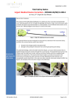
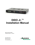
DIDO-0710
3U CompactPCI
Digital I/O Card
User Manual
13 Altalef St.
Yehud, Israel 56216
Tel: 972 (3) 632-0533
Fax: 972 (3) 632-0458
www.tenta.com
919 Kifer Road
Sunnyvale, CA 94086 USA
Tel: (408) 328-1370
Fax: (408) 328-1371
Document Revisions
Revision Comment
BY
Date
E2.0
Release
LL,
AF,RH
11/15/99
E2.3
Review and corrections
JR
03/10/00
E2.4
Added product revisions table, updated
format
DG
06/04/01
E3.0
Updated format
TJ
01/03/02
DIDO-0710 User Manual
Page 2 of 15
Table of Contents
I.
Introduction ..................................................................................... 4
II.
Ordering Information ...................................................................... 5
III.
Specifications .............................................................................. 6
A.
Physical Specifications ....................................................................... 6
B.
Environmental Specifications............................................................. 6
C.
Functional Specifications ................................................................... 7
D.
Power Specification............................................................................. 7
E.
I/O Circuitry Specification ................................................................... 7
F.
Digital Input Signals Specifications ................................................... 8
G.
Digital Output Signals Specifications ................................................ 8
H.
Watchdog timer.................................................................................... 9
I.
J2 Signals Distribution ........................................................................ 9
IV.
Block Diagram............................................................................ 10
V.
I/O Address Map ............................................................................ 11
VI.
Interrupts .................................................................................... 12
A.
Interrupt Handling.............................................................................. 12
B.
Interrupt Mask .................................................................................... 12
VII.
Test Procedure........................................................................... 13
VIII.
Product Revision History .......................................................... 14
IX.
Warranty ..................................................................................... 15
DIDO-0710 User Manual
Page 3 of 15
I. Introduction
This document describes the functionality of Tenta’s DI/O board 3U
CompactPCI form factor. This board design as general-purpose data
acquisition, 48 Digital I/O pins, and each pin can be used as Digital input
or Digital output. The I/O and power signals are distributed through J2
rear connector. The board form factor, physical dimension and BUS
interface complies with CompactPCI Specification PICMG 2.0 R2.1. The
board complies with Y2K requirement.
DIDO-0710 User Manual
Page 4 of 15
II. Ordering Information
Part Number
AS00710-01
DIDO-0710 User Manual
Description
Digital I/O board, 48 point, 3U cPCI, opto-isolated.
Page 5 of 15
III. Specifications
A. Physical Specifications
Criteria
PCB Dimensions
Form Factor
Connectors
Front Panel
Weight
Specifications
100MM (3.9370”) Height X 160MM
(6.2992”) Depth x 1.6MM (0.0629”)
Thickness
Plug in Euro card, 3U Height, 8 HP
Width (1 slot), IEEE (1101.1, 101.10
and P1101.11)
Metric 2.0mm grid, female connector
type A is used for J1 (cPCI BUS) and
J2 (Signal distribution).
128.5mm Height X 20.32mm Depth X
2.5 mm Thickness.
200g
B. Environmental Specifications
Criteria
Operating
temperature
Storage
Humidity
DIDO-0710 User Manual
Specifications
0-70 ºC
-40 to +85 ºC
5 to 95% non-condensing
Page 6 of 15
C. Functional Specifications
Criteria
BUS interface
Plug and Play
Front Panel
Indicators:
Watchdog timer
Protection
circuitry
Specifications
Compact PCI, 32 bit (16 bit data
transfer) 33MHz
Support auto recognition of the board
on power-on and plug-in includes
device ID, Vendor ID and configuration
RUN (HB), Power, In/Out Active 48
LEDs
Disable outputs (set all outputs to
Inactive (+24V) on timeout.
2A fuse on each output driver and a
suppression diode on each digital
input/output port.
D. Power Specification
Criteria
Digital Section
Power Supply
Output/input
Section Power
Supply
Specifications
+3.3VDC@ 20ma, +5VDC @ 220ma
from J1
+24V from J2, +5V EXT@ generated
on board
E. I/O Circuitry Specification
Criteria
Specifications
Number of I/O
48
signals
I/O signal function Each I/O can be used as Input OR
Output.
If used as output –output state can be
read back.
Number of I/O
48 green LEDs
front panel LEDs
DIDO-0710 User Manual
Page 7 of 15
F. Digital Input Signals Specifications
Criteria
Voltage Level
VIL
IMAX
VWITHSTAND
Isolation
Active Input
Inactive Input:
Specifications
Current-sinking, active low
<2V @ 8 mA sink, < 5V @ 15 mA
15 mA
5V min above actual voltage of 24V
DIO power supply
Min 100V
Min 6mA (input channel to DIO_COM)
Open or Max 3mA from the input
circuit.
G. Digital Output Signals Specifications
Criteria
Voltage Level
Current
Isolation
VOL
Specifications
Typical 24VDC, Min 18V DC,
Max 200 mA @24V DC
Min 100V
1.1V max. @ -100mA (sinking), 2V @ 200 mA
VOC
+18V
Current Limit
Max 500mA
Voltage
5V min above actual value of +24V
Withstand
DIO power supply
Off-state Leakage 100 µA max. @ 60V DC
Temperature
Driver built in thermal shutdown over
Limit
165 ºC with 10ºC thermal shutdown
Hysteresys
Fusing
2A fuse on each output driver.
Inactive state
24V
DIDO-0710 User Manual
Page 8 of 15
H. Watchdog timer
The Watchdog timer insures that cPCI bus communication with SBC is
alive. The watchdog timer must be reset by the SBC every 100msec to
avoid a time-out. If a time-out occurs, all digital outputs set to inactive
state. On time-out the watchdog timer latch on “watchdog fail” until
reinitialized by the SBC. On board jumper (JP3) allows to by-pass this
feature.
I. J2 Signals Distribution
Z
A
B
C
D
E
F
22 GND Reserved Reserved Reserved Reserved Reserved GND
21
20
19
18
17
16
15
14
13
12
11
10
9
8
7
6
5
4
3
2
1
GND Reserved Reserved Reserved Reserved Reserved GND
GND
GND
GND DI/O 44
DI/O 45
DI/O 46
DI/O 47
GND
GND DI/O 39
DI/O 40
DI/O 41
DI/O 42
DI/O 43 GND
GND Dig Com Dig Com Dig Com Dig Com Dig Com GND
GND DI/O34
DI/O 35
DI/O 36
DI/O 37
DI/O 38 GND
GND DI/O 29
DI/O 30
DI/O 31
DI/O 32
DI/O 33 GND
GND DI/O 24
DI/O 25
DI/O 26
DI/O 27
DI/O 28 GND
GND Dig Com Dig Com Dig Com Dig Com Dig Com GND
GND
GND
GND
GND
GND DI/O 20
DI/O 21
DI/O 22
DI/O 23
GND
GND Dig Com Dig Com Dig Com Dig Com Dig Com GND
GND DI/O 15
DI/O 16
DI/O 17
DI/O 18
DI/O 19 GND
GND DI/O 10
DI/O 11
DI/O 12
DI/O 13
DI/O 14 GND
GND
DI/O 5
DI/O 6
DI/O 7
DI/O 8
DI/O 9
GND
GND
DI/O 0
DI/O 1
DI/O 2
DI/O 3
DI/O4
GND
GND
24V
24Vret
24V
24Vret
Reserved GND
GND Reserved Reserved Reserved Reserved Reserved GND
GND Reserved Reserved Reserved Reserved Reserved GND
GND
3.3V
3.3V
3.3V
5V
5V
GND
DIDO-0710 User Manual
Page 9 of 15
IV. Block Diagram
OPTO
24V(External)
R
Serial Comm.
Output
Driver
x3
CK
PCI BRIDGE
CONTROL
LOGIC
OPTO
Serial Comm.
Output
Driver
x3
(DECODING,SERIAL COMM.
Heart Bit etc.)
EEPROM
16 bits
DATA BUS
BUFFER
PCI J2
Channels 24-47
LED0
HB RESET
R
Channels 0-23
LED47
HB RESET/OE
OPTO
DUAL
OPTO
X24
5V cPCI
LEDS
HB
POWER
DC to DC
CONVERTER
5V EXT
DIDO-0710 User Manual
ISOLATED POWER
Page 10 of 15
V. I/O Address Map
Board base address registers allocates 64 bytes within 32-bit memory
space. On power-up or system reset, all on-board control registers are
reset to 0. This sets all digital outputs to inactive state (high).
The following table defines the memory layout of the DIO710 relatively to
its base address. Bit 0 is the LSB of a 32 bit long word. Bits not defined
are considered don’t-care.
Offset
0
Register Description
Reset
R/W
W
Bit
0-31
4
Write Digital Ports 0-23
W
0-23
8
Write Digital Ports 24-47
W
0-23
4
Read Digital Ports 0-23
Output (0-23) busy
R
R
0-23
24
BIT Failed
R
27
WD Enable
WD Interval
WD Reset
R
R
R
28
29-30
31
8
Read Digital Ports 24-47
Output (24-47) busy
R
R
0-23
24
16
Watchdog Timer
W
0
W
4-5
W
8
20
BIT LED control
Interrupt Mask 0-23
W
W
12
0-23
24
Interrupt Mask 24-47
W
0-23
DIDO-0710 User Manual
Bit Range Description
Reset
By writing any value.
Write Values,
Output triggers refresh.
Write Values,
Output triggers refresh.
Read Values
Output refresh taking place.
Busy = 0, Ready = 1
Hardware Built-In-Test failed
indicator
Watch dog enabled
Watch dog Time-out interval.
Reset Activated
(Occurred = 0)
Read Values
Output refresh taking place.
Busy = 0, Ready = 1
Enable watchdog.
Enable = 1
Time-out interval.
100mS = 00
200mS = 01
400mS = 10
800mS = 11
Report Reset Occurrence
(Report = 1)
BIT LED
Mask values.
Interrupt enabled = 1
Mask values.
Interrupt enabled = 1
Page 11 of 15
VI. Interrupts
A. Interrupt Handling
This section is for future reference.
The application may register a change in the value of an input port that
was masked as interrupt enabled. Once there was a change in digital
input the board will force an interrupt over the PCI bus via INTA# signal.
B. Interrupt Mask
The driver should avoid enabling an interrupt to a port defined as output.
Such definition is miss-configuration.
DIDO-0710 User Manual
Page 12 of 15
VII. Test Procedure
The functionality of all digital outputs and digital inputs are examined by
an automatic test procedure (ATP). DIO710 consists of 48 Digital I/O
pins; each pin can be used as Digital input or Digital output. Software
configurable, due to this fact each two consequent pins are connected
together by an external loop-back connector and load (Iout=200mA)
resistors. The ATP program checks validation of each digital output path
and the consequent digital input that is connected to that digital output.
DIDO-0710 User Manual
Page 13 of 15
VIII.Product Revision History
Rev
E1
B
Changes
Original
Change C3 to 35VDC model
C
Change EPROM to 710.30
Reason
Capacitor has marginal voltage
specification
2us spikes on DO lines during
write operation
All boards of Rev. E1 should be discarded. All other boards under Rev. C
can be returned to Tenta for upgrade.
DIDO-0710 User Manual
Page 14 of 15
IX. Warranty
Tenta Technology warrants the original purchaser for two years from the
date of delivery for any defect in the product, material or workmanship.
Product should be used in suitable installation environment and for the
purposes it was designed. Any damages caused by natural disasters such
as: fire, flood, wind and lightning are not covered. For more information,
please contact Tenta Technology customer support (see locations on
front page). Tenta Technology hardware and software are not intended
for use in any manner when human life or safety is at risk and not for use
in life support equipment.
DIDO-0710 User Manual
Page 15 of 15