1
P.O. BOX 75 Yehud 56100, Israel
Tel: +972 3 531 5350; Fax: +972 3 531 5138
POP200/300
Observation Payload
User’s Guide
Release #5, August 2004
Doc No: A-1346.0037.00.00-1756-4.05
This document contains proprietary information of Israel Aircraft Industries Ltd. And may not be reproduced, copied,
disclosed or utilized in any way, in whole or in part, without the prior written consent of Israel Aircraft Industries Ltd.
POP200 User Manual. Rev #5, August 2004
Page 1
Doc: A-1346.0037.00.00-1756-4.05
P.O. BOX 75 Yehud 56100, Israel
Tel: +972 3 531 5350; Fax: +972 3 531 5138
Table of Contents
1
Introduction ............................................................................................................. 7
1.1
Application .............................................................................................7
1.2
General Description and Background........................................................8
1.3
Operating Voltage...................................................................................9
1.4
General Installation Guidelines...............................................................11
1.5
Functional Block Diagram ......................................................................13
1.6
POP200 Operation Guidelines ................................................................14
2
Payload Operation. ........................................................................................15
2.1
Connections and Initial Operation. .........................................................15
2.1.1
Connections.............................................................................15
2.1.2
Initial Operation.......................................................................16
2.2
Image Reception and Selection..............................................................17
2.2.1
Image Reception .....................................................................17
2.2.2
Display ....................................................................................19
2.2.3
Video Outputs Logic .................................................................19
2.2.4
IR Image.................................................................................20
2.2.5
TV Image ................................................................................20
2.2.6
Controlling the Secondary video output. ....................................20
2.3
System Shutdown. ................................................................................21
2.4
Piloting (Slewing) the LOS. ....................................................................24
2.4.1
Line of Sight (LOS) ..................................................................24
2.4.2
The Force Transducer (FT) Pushbutton ....................................24
2.4.3
Report on System Status and Position .......................................25
2.4.4
INERTIAL Mode .......................................................................25
2.4.5
POSITION (Heading Hold) Mode ..............................................25
2.4.6
STOW Position.........................................................................26
2.4.7
AUTO SCAN.............................................................................28
2.4.8
Cage Mode (Operator Window).................................................30
2.5
Track Mode ..........................................................................................32
2.5.1
Description ..............................................................................32
2.5.2
Tracker Submodes ...................................................................32
2.5.3
Track Mode - Selection and Operation.......................................35
2.5.4
Exiting Track Mode ..................................................................36
2.5.5
Prediction Mode .......................................................................36
3
Controlling and Optimizing the Image Quality .................................................37
3.1
FLIR Channel........................................................................................37
3.1.1
FLIR Focus ..............................................................................37
3.1.2
Focus to Infinity.......................................................................37
3.1.3
FLIR Focus Memory. ................................................................37
3.1.4
IR Fields Of Views (FOV) ..........................................................38
3.1.5
FLIR Polarity............................................................................38
3.1.6
FLIR Gain/Level Control............................................................39
3.1.7
FLIR Semi Automatic AGC ........................................................40
3.1.8
Freeze the FLIR Image.............................................................40
3.1.9
Non-uniformity Tables Replacement..........................................41
3.1.10
Automatic (One Point) – Non Uniformity Correction....................43
3.2
DTV Channel – for POP Models 200 .......................................................46
This document contains proprietary information of Israel Aircraft Industries Ltd. And may not be reproduced, copied,
disclosed or utilized in any way, in whole or in part, without the prior written consent of Israel Aircraft Industries Ltd.
POP200 User Manual. Rev #5, August 2004
Page 2
Doc: A-1346.0037.00.00-1756-4.05
P.O. BOX 75 Yehud 56100, Israel
Tel: +972 3 531 5350; Fax: +972 3 531 5138
3.2.1
DTV Focus...............................................................................46
3.2.2
DTV Zoom. ..............................................................................47
3.2.3
DTV - Shutter Speed Control. ...................................................47
3.3
DTV Channel – Model 200-6 ..................................................................48
3.3.1
What is New? ..........................................................................48
3.3.2
Near IR ...................................................................................48
3.3.3
DTV Focus...............................................................................49
3.3.4
DTV Zoom. ..............................................................................49
3.3.5
Freeze the DTV Image. ............................................................49
3.3.6
DTV Modes of Operation ..........................................................51
4
Manipulate the Image symbols.......................................................................56
4.1
Symbology Layers Modification ..............................................................56
4.2
Symbology Hue Modification..................................................................57
4.3
Modify Azimuth Reading........................................................................58
5
Laser Range Finder Operation ........................................................................60
5.1
General ................................................................................................60
5.2
Operation.............................................................................................60
5.2.1
Ranging ..................................................................................60
5.2.2
When Ranging is Allowed. ........................................................61
5.2.3
Range Display..........................................................................62
5.2.4
Setting LRF parameters ............................................................63
5.3
Ranging Fail .........................................................................................64
5.4
No Fire Zones Window ..........................................................................64
5.4.1
Setting and Update the “No Fire Zones” Window. ......................64
5.4.2
Canceling the “No Fire Zone”. ...................................................67
5.4.3
Definition of a reversed “No Fire Zone”. ...................................67
6
Laser Pointer Sensor - Safety Instructions and Operation.................................68
6.1
General ................................................................................................68
6.2
Detail Safety Instructions. .....................................................................70
6.2.1
Important Guidlines .................................................................70
6.2.2
LPS Operation Actions Highlight................................................70
6.2.3
Medical Evacuation ..................................................................71
6.3
Laser Pointer Operating Instructions ......................................................71
6.3.1
No Fire and Safety Zones definitions .........................................72
6.3.2
LPS Safety Zone ......................................................................72
6.3.3
No Fire Zone............................................................................72
6.3.4
Triggering the LPS ...................................................................73
6.3.5
Firing the LPS ..........................................................................74
6.4
Update the No Fire and Safety Zones definitions.....................................75
6.4.1
Update the Safety Zones definitions ..........................................75
6.4.2
Update the No Fire Zones definitions.........................................75
6.5
Using the LPS when No Fire window is Active .........................................76
6.5.1
Canceling the “No Fire Zone”. ...................................................77
6.5.2
Definition of a reversed “No Fire Zone”. ...................................77
6.5.3
LPS Abort, Modes. ...................................................................78
6.6
Symbology Glossary Updates for LPS .....................................................78
7
Modify System Default values.........................................................................79
7.1
CAGE Pointing Direction. .......................................................................79
7.2
AUTO SCAN..........................................................................................79
7.3
Fine Tune of DTV Shutter Speed (POP200).............................................79
This document contains proprietary information of Israel Aircraft Industries Ltd. And may not be reproduced, copied,
disclosed or utilized in any way, in whole or in part, without the prior written consent of Israel Aircraft Industries Ltd.
POP200 User Manual. Rev #5, August 2004
Page 3
Doc: A-1346.0037.00.00-1756-4.05
P.O. BOX 75 Yehud 56100, Israel
Tel: +972 3 531 5350; Fax: +972 3 531 5138
7.4
Secondary Video Output Source.............................................................80
7.5
Symbology Hue ....................................................................................80
7.6
Automatic One-point NUC Correction - Direction .....................................81
7.7
Time and Date......................................................................................81
7.8
Restore Defaults. ..................................................................................82
7.9
Laser Range Finder (LRF) No Firing Zone Definition. ...............................82
7.10
Laser Pointer (LP) No Firing Zone Definition. ..........................................82
8
Slaving Modes of the Payload.........................................................................83
8.1
POP200 Operation with Nav. System (GPS). ...........................................83
8.1.1
General ...................................................................................83
8.2
POP200 Operation with RADAR..............................................................84
8.2.1
General ...................................................................................84
8.2.2
Data Formatting ......................................................................84
8.2.3
Operation ................................................................................86
8.2.4
Slave Attitude Error Calibration. ................................................88
8.2.5
General Guidelines ...................................................................88
8.2.6
RADAR Fail or Off. ...................................................................89
8.3
POP200 Operation, With Two HCGs. ......................................................90
8.3.1
General ...................................................................................90
8.3.2
Power up and priority...............................................................90
8.3.3
Switch control between the HCGs. ............................................91
9
Non-uniformity Correction..............................................................................92
9.1
Background ..........................................................................................92
9.2
User Correction 1- Point External (Preferred). .........................................93
9.3
User Correction 1- Point, Internal. .........................................................96
10 System Menu ................................................................................................97
10.1
General Description...............................................................................97
10.2
Entry and Exit.......................................................................................97
10.3
How to Navigate within the Menu. .........................................................98
10.4
How Control the MENU in a Remote Host Operation. ..............................98
10.5
Common Modifications in MENU Mode ...................................................98
10.6
MENU Detailed Description .................................................................. 102
11 Symbology Legend and Glossary .................................................................. 108
11.1
Symbology Layout – Basic ................................................................... 108
11.2
Symbology Layout – With LRF ............................................................. 109
11.3
Symbology Layout – With Radar and GPS integrated............................. 110
11.4
Symbology Glossary............................................................................ 111
12 BIT............................................................................................................. 120
12.1
Turret BIT .......................................................................................... 120
13 Tips and Tricks............................................................................................ 121
13.1
Display the Mean and Sigma of the FLIR. ............................................. 121
13.2
Changing the LOS Maximum Rate. ....................................................... 121
13.2.1
FLIR Channel......................................................................... 121
13.2.2
DTV (EO) Channel ................................................................. 122
13.2.3
General ................................................................................. 122
13.3
System Standby.................................................................................. 122
13.4
Matching FOVs ................................................................................... 123
13.5
Set LOS sector limits ........................................................................... 123
14 HCG Switches Assignment ........................................................................... 124
This document contains proprietary information of Israel Aircraft Industries Ltd. And may not be reproduced, copied,
disclosed or utilized in any way, in whole or in part, without the prior written consent of Israel Aircraft Industries Ltd.
POP200 User Manual. Rev #5, August 2004
Page 4
Doc: A-1346.0037.00.00-1756-4.05
P.O. BOX 75 Yehud 56100, Israel
Tel: +972 3 531 5350; Fax: +972 3 531 5138
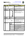
Terms and Abbreviations
A
AGC
AS
AZ
-
Automatic Gain Control
Auto-Scan
Azimuth
BH
-
Black-Hot
CFG
CG
-
Configuration.
Cage.
DC
DTV
-
Direct Current
Day Television
EL
ELZM
ETI
EXP
-
Elevation
Electronic Zoom
Elapsed Time Indicator
Exposure
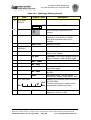
FLIR
FOR
FOV
FT
FZ
-
Forward Looking Infra-Red
Field of Regard
Field of View
Force Transducer.
Freeze
G/L
GN
-
Gain/Level
Gain.
HB
H/W
HC
HCG
HH
-
Hot Black
Hardware
Host Controller
Hand Control Grip
Heading Hold
ID
INRT
IP
IR
IRC
IT
-
Inner Diameter
Inertial
Inertial Position
Infra-Red
IR Camera
Integration Time
LOS
LPS
LRF
-
Line of Sight.
Laser pointer sensor.
Laser Range finder
MFOV
MFS
-
Medium FOV
Multi-Function Scale
B
C
D
E
F
G
H
I
L
M
This document contains proprietary information of Israel Aircraft Industries Ltd. And may not be reproduced, copied,
disclosed or utilized in any way, in whole or in part, without the prior written consent of Israel Aircraft Industries Ltd.
POP200 User Manual. Rev #5, August 2004
Page 5
Doc: A-1346.0037.00.00-1756-4.05
P.O. BOX 75 Yehud 56100, Israel
Tel: +972 3 531 5350; Fax: +972 3 531 5138
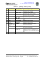
Terms and Abbreviations (Cont'd)
N
NAV
NFOV
NIR
NUC
-
Navigation
Narrow FOV
Near IR
Non-Uniformity Correction
O
OD
O-level -
Outer Diameter
Organizational Maintenance Level
PLT
POP
PP
PRI
PSU
-
Plate
Plug-in Optronic Payload
Present Position.
Priority
Power supply unit
RDR
RG
-
Radar
Range Gates
S/W
SHTR
SINI
SLV
SNAR
STBY
STD
-
Software
Shutter.
Slice Initialization.
Slave
Super narrow (FOV)
Stand-By
Standard
TBL
TINI
TOD
TRCK
TRT
TV
-
Table
Turret Initialization.
Time of Day
Track
Turret
Television
VCR
-
Video Cassette Recorder
WH
WFOV
-
White-Hot
Wide Field of View
P
R
S
T
V
W
This document contains proprietary information of Israel Aircraft Industries Ltd. And may not be reproduced, copied,
disclosed or utilized in any way, in whole or in part, without the prior written consent of Israel Aircraft Industries Ltd.
POP200 User Manual. Rev #5, August 2004
Page 6
Doc: A-1346.0037.00.00-1756-4.05
P.O. BOX 75 Yehud 56100, Israel
Tel: +972 3 531 5350; Fax: +972 3 531 5138
1 Introduction
This document describes the operation and guidelines for proper use of the
POP200/300, POP200-6, (enhanced DTV), POP200P (with LP) and
POP200TS/300TS (Three sensors), optronic payloads. Read this manual carefully
in order to get the most out of the product. If you have any question or require
assistance, please call TAMAM customer service department. This document
contains also important safety instructions and operation information on the
POP200P, which contains a non-eye safe laser pointer (LP) sensor.
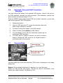
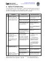
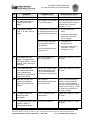
Appendix A provides field level maintenance instructions and on-site
troubleshooting for the payload. It contains the required guidelines to maintain
the payload at the organizational ("O") maintenance level.
A separate chapter is dedicated to the enhanced Day TV channel, which
characterizes the POP200-6 and POP300.
µ Safety Note:
A POP200P and POP300 version contains a Laser Pointer Sensor
(LPS). When this sensor is active, and points toward a human eye, it
may cause a permanent damage to the eye.
If the payload that you have purchased contains the LPS, than read
first carefully the safety instruction at chapter 6.2 in this manual.
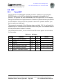
1.1
Application
This manual is for POP200 or POP300 units with software versions as follows:
Turret: #11 or higher.
Slice:
#15 or higher.
As of August 2004 the latest SW versions are: Turret #11 and Slice #15.
Also the following SW version is available:
♦
Turret #12 and Slice #16.
♦
Turret #13 and Slice #17.
This manual covers also the operation of additional POP200/300 sensors and
features which are optional:
Laser Range finder (LRF).
Laser pointer Sensor (LPS)
Enhanced DTV channel (POP200-6)
Payload integration with NAV/RADAR.
Payload operation with dual HCGs.
This document contains proprietary information of Israel Aircraft Industries Ltd. And may not be reproduced, copied,
disclosed or utilized in any way, in whole or in part, without the prior written consent of Israel Aircraft Industries Ltd.
POP200 User Manual. Rev #5, August 2004
Page 7
Doc: A-1346.0037.00.00-1756-4.05
P.O. BOX 75 Yehud 56100, Israel
Tel: +972 3 531 5350; Fax: +972 3 531 5138
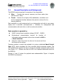
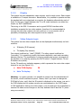
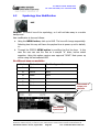
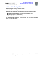
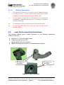
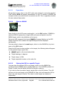
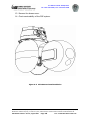
1.2
General Description and Background.
The POP200 optronic payload is comprises of two assemblies:
Slice:
Contains the sensors, cameras, and there optics (also
referred to as "slice").
Turret: Used as line of sight (LOS) stabilization, orientation and
as the mechanical interface between the optronic unit and for the
carrying platform.
Each assembly is a self-contained and is an independent unit with its own power
supply and a controller (microprocessor + software) for management and
communication with each other or with an external controller.
Each assembly is operated by:
¨
28VDC nominal input operation voltage (22 VDC ÷ 32VDC).
¨
Bi-directional communication channel for transfer of
information and commands to/from the unit and the HCG or
a Host Controller.
¨
Output of video lines from the slice to the turret and from
the turret to the monitor.
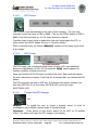
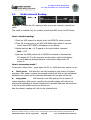
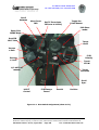
Common practice to control the payload is by using a dedicated Hand Control
Grip (HCG), which simulates the host controller serial commands stream. The
HCG contains the required hot key to access the payload commands and controls
(see Figure 1-2). (Please note that the HCG is an optional deliverable device to
the POP200).
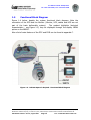
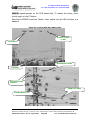
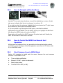
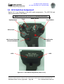
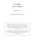
Figures 1-1 and 1-2 shows the payload main subassemblies. Figure 1-4 depicts
the POP200 architecture.
This document contains proprietary information of Israel Aircraft Industries Ltd. And may not be reproduced, copied,
disclosed or utilized in any way, in whole or in part, without the prior written consent of Israel Aircraft Industries Ltd.
POP200 User Manual. Rev #5, August 2004
Page 8
Doc: A-1346.0037.00.00-1756-4.05
P.O. BOX 75 Yehud 56100, Israel
Tel: +972 3 531 5350; Fax: +972 3 531 5138
System principle of operation is as follows:
a.
The 28 VDC operating voltage is fed directly to the turret. The system is
still in the OFF position since the ON/OFF signal from the host or the HCG
to the power supply in the turret is not active.
b.
When the ON signal becomes active (low), power is applied to the turret,
which then feed it to the slice, and the payload becomes active.
c.
The host transmits the STBY command (or the HCG switch is set to
STBY), setting the system to standby mode.
d.
The turret power supply activates the power supplies in the optronic unit
(and in the HCG if applicable). Communication is established between the
two subassemblies and the host controller.
The turret verifies that the communication among the three elements: (a) turret,
(b) slice and (c) HCG/host is OK. If so, the optronic unit activates the video
signals and the turret activates the line of sight (LOS) stabilization system and
LOS movements control. Once a pushbutton on the HCG is pressed, its proper
command to the turret or slice is activated.
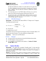
1.3
Operating Voltage.
The nominal operation voltage is +28 VDC, which is received from an external
power supply. If the Payload is installed in a considerable long distance from the
driving power supply source (several tens of meters), there is a voltages drop of
several volts on the operation cable, causing the voltage received at the Payload
terminals to be lower than the voltage output by the power supply. In such
cases, the power supply output voltage should be trimmed to be higher than the
nominal, typically 32 volts.
This document contains proprietary information of Israel Aircraft Industries Ltd. And may not be reproduced, copied,
disclosed or utilized in any way, in whole or in part, without the prior written consent of Israel Aircraft Industries Ltd.
POP200 User Manual. Rev #5, August 2004
Page 9
Doc: A-1346.0037.00.00-1756-4.05
P.O. BOX 75 Yehud 56100, Israel
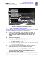
Tel: +972 3 531 5350; Fax: +972 3 531 5138
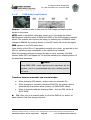
IR
Window
Purging
Valve
TV
Window
J1, J2
Electrical
Interface
Outer Ring
Mechanical
Interface
Humidity
Indicator
Dovetail
Mechanical
Interface
Azimuth
Gimbal
Payload
Front
Slice
Elevation
Gimbal
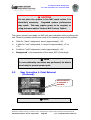
Figure 1-1. POP200 Optronic Payload - Main Components
HCG Hot Keys
Figure 1-2. Hand Control Grip (HCG) for POP200
This document contains proprietary information of Israel Aircraft Industries Ltd. And may not be reproduced, copied,
disclosed or utilized in any way, in whole or in part, without the prior written consent of Israel Aircraft Industries Ltd.
POP200 User Manual. Rev #5, August 2004
Page 10
Doc: A-1346.0037.00.00-1756-4.05
P.O. BOX 75 Yehud 56100, Israel
Tel: +972 3 531 5350; Fax: +972 3 531 5138
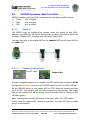
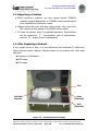
1.4
General Installation Guidelines
When installing the payload in the laboratory or anywhere else – for operation,
make sure that you follow the following guidelines:
¨
Always use a stiff mechanical stand to mount the
payload.
¨
Secure the payload to the carrying vehicle or stand,
via the dovetail interface or the six screws outer ring
(M4).
¨
Always connect the electrical connectors before
applying power.
¨
Check carefully for proper connection of the input
power polarity.
¨
Before applying power to the unit remove the FLIR
window cover (red cover).
¨
When operating the payload make sure external
objects do not obscure its LOS, even partially.
¨
Verify that appropriate metal cover (supplied with the
payload) always protects the TEST connector (J2).
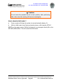
¨
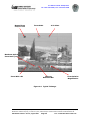
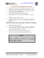
The payload is delivered in a mobile, reusable
container. When not installed on board, always keep
the payload in its original container (see Figure
1-3).
This document contains proprietary information of Israel Aircraft Industries Ltd. And may not be reproduced, copied,
disclosed or utilized in any way, in whole or in part, without the prior written consent of Israel Aircraft Industries Ltd.
POP200 User Manual. Rev #5, August 2004
Page 11
Doc: A-1346.0037.00.00-1756-4.05
P.O. BOX 75 Yehud 56100, Israel
Tel: +972 3 531 5350; Fax: +972 3 531 5138
Figure 1-3. POP200 Original Container
This document contains proprietary information of Israel Aircraft Industries Ltd. And may not be reproduced, copied,
disclosed or utilized in any way, in whole or in part, without the prior written consent of Israel Aircraft Industries Ltd.
POP200 User Manual. Rev #5, August 2004
Page 12
Doc: A-1346.0037.00.00-1756-4.05
P.O. BOX 75 Yehud 56100, Israel
Tel: +972 3 531 5350; Fax: +972 3 531 5138
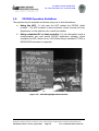
1.5
Functional Block Diagram
Figure 1-4 below, depicts the system functional block diagram. Note the
connection of the VCR and the Monitor. (Monitor, VCR, cables and HCG are not
part of the basic deliverable system).
The product highlights (technical
characteristics - see Figure 1-5) may be displayed through the display MENU
option on the ABOUT.
Also a list of main features of the DTV and FLIR can be found at appendix C.
Figure 1-4. POP200 Optronic Payload - Functional Block Diagram
This document contains proprietary information of Israel Aircraft Industries Ltd. And may not be reproduced, copied,
disclosed or utilized in any way, in whole or in part, without the prior written consent of Israel Aircraft Industries Ltd.
POP200 User Manual. Rev #5, August 2004
Page 13
Doc: A-1346.0037.00.00-1756-4.05
P.O. BOX 75 Yehud 56100, Israel
Tel: +972 3 531 5350; Fax: +972 3 531 5138
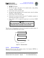
1.6
POP200 Operation Guidelines
The payload may be operated and driven using one of two alternatives:
a.
Using the HCG. In this case the HCG realizes the POP200 uplink
protocol. The HCG contains a micro-controller, which converts the user
depressions on the switches into a serial bus stream.
b.
Using a standard PC or host controller. For this alternative needs a
communication port and special POP200 application software, which
emulates the HCG, which run on a PC (When using a standard PC COM, a
RS232/RS422 converter is required).
Figure 1-5. POP 200 Highlight Characteristics
This document contains proprietary information of Israel Aircraft Industries Ltd. And may not be reproduced, copied,
disclosed or utilized in any way, in whole or in part, without the prior written consent of Israel Aircraft Industries Ltd.
POP200 User Manual. Rev #5, August 2004
Page 14
Doc: A-1346.0037.00.00-1756-4.05
P.O. BOX 75 Yehud 56100, Israel
Tel: +972 3 531 5350; Fax: +972 3 531 5138
2 Payload Operation.
2.1
Connections and Initial Operation.
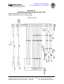
The payload may be connected to the carrying platform in several ways,
depending on the payload application and usage. Typical connection describes in
appendix B. However ,when the payload is integrated with RADAR or GPS, other
configuration may be used.
2.1.1
Connections
The payload has one operational (signal) connector, J1. Use a standard POP200
Operating cable, see appendix B (optionally supplied by TAMAM), or use the
drawing at appendix B to build a proper cable for yourself.
Make sure for the following connections:
a.
Before any connection is made, turn your PSU to ON and read its
output voltage. Make sure it is 22 to 32 VDC, not above. Turn power
off.
b.
Power leads to the 28VDC
supply. Before any connection is
made, identify clearly the polarity leads of the payload input power
operating cable.
c.
Repeat this check for your driving PSU. Failing to connect the leads
power in the proper polarity may cause damage to the payload.
d.
Only after the above steps, complete the connections:
e.
Prime video output to one monitor (or VCR).
f.
J2 connector to the HCG or to host controller via J2 mating
connector.
g.
While the HCG ON/OFF switch is in OFF state, turn ON the 28VDC
power and see zero current.
This document contains proprietary information of Israel Aircraft Industries Ltd. And may not be reproduced, copied,
disclosed or utilized in any way, in whole or in part, without the prior written consent of Israel Aircraft Industries Ltd.
POP200 User Manual. Rev #5, August 2004
Page 15
Doc: A-1346.0037.00.00-1756-4.05
P.O. BOX 75 Yehud 56100, Israel
Tel: +972 3 531 5350; Fax: +972 3 531 5138
2.1.2
Initial Operation
ON-OFF
switch
Amber Light
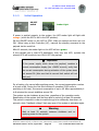
If power is applied properly to the system, the HCG amber light will light with
orange. (when the HCG is still in the OFF position).
Set the ON/OFF switch on the HCG to STBY. Wait one second and then set it to
ON. When using a Host Controller (HC), transmit the standby command to the
payload via the serial link.
After 60 seconds, the amber light on the HCG will turn green.
If the payload uses a dual HCG application, than only one HCG, typically the
primary HCG will be able to turn ON or OFF the payload.
⌦
Important:
If the power supply which drives the payload, contains a
current consumption display (the +28VDC current), verify that
the current consumption during activation of the system does
not exceed 5A (Also see that its current limit switch will not
limit you).
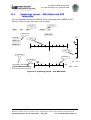
For a fraction of a second after applying power, the current consumption reaches
of a peak of 8A. During the first few minutes of operation (FLIR cooler is
operating in full rate), the current consumption is up to 4A. After approximately 4
to 8 minutes the current stabilizes around 3A.
The system can be shutdown at any time, regardless of the operation mode.
Reactivation of the system shall be done after a period of at least 30 seconds.
This period is required in order to enable the gyro to sufficiently slow down, to
prevent a high "feedback voltage" that may occur if the system is activated again.
µ
Warning
Wait at least 30 seconds, between shutdown and reapplying power to the system.
This document contains proprietary information of Israel Aircraft Industries Ltd. And may not be reproduced, copied,
disclosed or utilized in any way, in whole or in part, without the prior written consent of Israel Aircraft Industries Ltd.
POP200 User Manual. Rev #5, August 2004
Page 16
Doc: A-1346.0037.00.00-1756-4.05
P.O. BOX 75 Yehud 56100, Israel
Tel: +972 3 531 5350; Fax: +972 3 531 5138
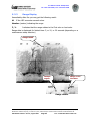
2.2
2.2.1
Image Reception and Selection.
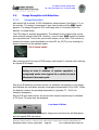
Image Reception
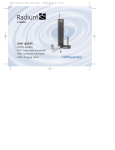
After about half a minute, a FLIR initialization image appears (see Figure 2-1) on
the monitor. The image is composed of gray hues screen and the SINI legend
appears. The image changes to FLIR real image after 4-5 minutes (when the
detector is cooled-down).
The DTV image is received immediately. The default for the output video on the
prime channel output is the FLIR. However, once the slice SINI legend is cleared,
you may select the TV to be the prime video output, at any time. This is done by
pressing the sensor mode pushbutton on the HCG, up, IR/TV (or by sending the
proper command via the payload uplink.
IR/TV Select switch
After receiving the first snap of FLIR image, wait another 2 minutes until receiving
an optimal FLIR image.
⌦ Note
During at least 6 minutes of system operation, a
background audio noise typical for a cooler is heard.
Afterward it becomes quiet.
During the IR detector cool-down period, an indication bar appears on the image
and indicates the cool-down process convergence temperature of the FLIR. When
the detector reaches its operating temperatures, (typically 77 - 80°K) the
indication disappears.
During FLIR cool-down period, the prime video output channel may be switched
to TV and a TV image may be displayed.
Cool down FLIR bar
Note: You may have FLIR Initialization image and cool down bar still decreasing
and the legend SINI gone away.
This document contains proprietary information of Israel Aircraft Industries Ltd. And may not be reproduced, copied,
disclosed or utilized in any way, in whole or in part, without the prior written consent of Israel Aircraft Industries Ltd.
POP200 User Manual. Rev #5, August 2004
Page 17
Doc: A-1346.0037.00.00-1756-4.05
P.O. BOX 75 Yehud 56100, Israel
Tel: +972 3 531 5350; Fax: +972 3 531 5138
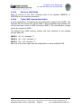
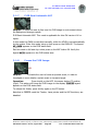
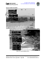
Turret
Standby Mode
Slice
Initialization
FLIR Cool-Down Bar
System FOV
Status
Time and
Date
Gain/Level Auto/Man
Indication
Figure 2-1. FLIR Initialization Image
Turret Mode
Prime video status
Selection
IR Polarity
Status
NFOV
Reticle
Figure 2-2. IR/TV Indication
This document contains proprietary information of Israel Aircraft Industries Ltd. And may not be reproduced, copied,
disclosed or utilized in any way, in whole or in part, without the prior written consent of Israel Aircraft Industries Ltd.
POP200 User Manual. Rev #5, August 2004
Page 18
Doc: A-1346.0037.00.00-1756-4.05
P.O. BOX 75 Yehud 56100, Israel
Tel: +972 3 531 5350; Fax: +972 3 531 5138
2.2.2
Display
The system has two independent video outputs, one for each sensor. Each output
is available on J1 output connector. Nevertheless, it is possible to operate and use
the payload with one output and one monitor for displaying alternatively each of
them. In this case, toggle between the TV or IR video sources to one video line
output, by IR/TV pushbutton.
The wiring in the POP J1 connector and a typical POP200 interface cable
installation supports the two video outputs, therefore it is recommended to
connect the two video outputs into two monitors or to one monitor with a
possibility of displaying two video signals from two outputs.
2.2.3
Video Outputs Logic
The system has two video outputs that can be displayed simultaneously on both
monitors.
a.
IR display (FLIR camera)
b.
TV display (Day camera)
One output is defined as "main" (PRIME). The other output is defined as
"secondary". It is possible to modify the sensors definition, main and secondary,
between the two. The modification is done by sending the proper commands to
the payload, or by pushing pressing the IR/TV button. (Toggle between TV and
IR sensors as a prime).
On the TV monitor an indication appears, which represents the main video output
channel in use (see Figure 2-2):
a. Main FLIR display:
IR
b. Main TV display:
TV
Meaning: in a given moment, it is possible to control only the characteristic of
the sensor, which is defined as prime. Means, that if you want to change the
FLIR field of view, verify that the IR symbol is displayed on the screen, you are in
the FLIR display and the system cursors are superimposed on the FLIR image.
In POP applications having one video output, (one physical line) the pushbutton is
used as the video source changer on the line, between the IR and the TV (when
using one monitor).
This document contains proprietary information of Israel Aircraft Industries Ltd. And may not be reproduced, copied,
disclosed or utilized in any way, in whole or in part, without the prior written consent of Israel Aircraft Industries Ltd.
POP200 User Manual. Rev #5, August 2004
Page 19
Doc: A-1346.0037.00.00-1756-4.05
P.O. BOX 75 Yehud 56100, Israel
Tel: +972 3 531 5350; Fax: +972 3 531 5138
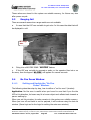
2.2.4
IR Image
The default prime image is FLIR. The system FLIR image at power up, has the
following parameters: Non-uniformity correction (NUC) table #1, (with 2.0
milliseconds exposure time) which its indication on the screen is WARM. Figure 23 shows a typical IR image with the symbology.
The FLIR FOV is wide WFOV and its focus goes to the “infinity” point. (And so for
every FOV providing it is the first swathing to that FOV).
2.2.5
TV Image
The default secondary video output is the TV. Switching to TV is possible also
during the FLIR initialization process while the SINI indicator is still on the screen.
The DTV goes to its last set zoom and looks for automatically for the focus.
Figure 2-4 shows a typical TV image and its overlay symbology.
Note:
If the payload is integrated with RADAR or GPS, and one or both of
them is active, than additional data will appear on the image (See section 8):
Platform heading
HDG
Platform Present Position PP
Time and day will be synchronized to the GPS. (unless the user has selected not
to, via the MENU).
2.2.6
Controlling the Secondary video
output.
The default secondary video output is the TV. You may set the secondary output,
to be the same as the primary. The benefit is that one can have the video output
with the payload symbology and at the same time a clean video for the user
applications. Go the system menu, system configuration and select the line
SECONDARY = PRIMARY.
Note that the status of this selection is stored in the system nonvolatile memory,
for future operation – until next change.
This document contains proprietary information of Israel Aircraft Industries Ltd. And may not be reproduced, copied,
disclosed or utilized in any way, in whole or in part, without the prior written consent of Israel Aircraft Industries Ltd.
POP200 User Manual. Rev #5, August 2004
Page 20
Doc: A-1346.0037.00.00-1756-4.05
P.O. BOX 75 Yehud 56100, Israel
Tel: +972 3 531 5350; Fax: +972 3 531 5138
Select which video output will be
displayed on the secondary video
output
System default is that the secondary output is set to be the other video which is
on the primary output.
2.3
System Shutdown.
Before system shuts down, it is recommended to bring the line of sight to STOW
position to protect the FLIR lens. This position is +90° in elevation. Press on
STOW shortly from any position. Wait until the system will reach to a position of
+90° in elevation and 180° in azimuth (about 5 seconds). In this position, shut
down the system.
This position is assigned to protect the camera window by hiding it.
Before any power restart, wait at least 30 seconds, after shut down.
µ Caution!
Never disconnect the POP cables while its input power
source is ON (active).
In case that the system is using the FLIR optical magnifier, than the STOW
position will be +15° in elevation and backwards.
This document contains proprietary information of Israel Aircraft Industries Ltd. And may not be reproduced, copied,
disclosed or utilized in any way, in whole or in part, without the prior written consent of Israel Aircraft Industries Ltd.
POP200 User Manual. Rev #5, August 2004
Page 21
Doc: A-1346.0037.00.00-1756-4.05
P.O. BOX 75 Yehud 56100, Israel
Tel: +972 3 531 5350; Fax: +972 3 531 5138
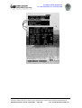
FRIME
video
NFOV
Reticle
EL Bar
AZ Bar
Integratio
n Time
Gain
IR Camera
Status
WARM
IT 2.2
GN 66
MFOV
Reticle
Figure 2-3. Typical IR Image
This document contains proprietary information of Israel Aircraft Industries Ltd. And may not be reproduced, copied,
disclosed or utilized in any way, in whole or in part, without the prior written consent of Israel Aircraft Industries Ltd.
POP200 User Manual. Rev #5, August 2004
Page 22
Doc: A-1346.0037.00.00-1756-4.05
P.O. BOX 75 Yehud 56100, Israel
Tel: +972 3 531 5350; Fax: +972 3 531 5138
Manual Zoom
and/or Focus
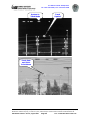
Turret Mode
TV is Prime
Maximum Optical
Zoom Ratio (x16)
TV Zoom
Reference Bar
Zoom Wide =X1
Zoom Relative
Magnification
Figure 2-4. Typical TV Image
This document contains proprietary information of Israel Aircraft Industries Ltd. And may not be reproduced, copied,
disclosed or utilized in any way, in whole or in part, without the prior written consent of Israel Aircraft Industries Ltd.
POP200 User Manual. Rev #5, August 2004
Page 23
Doc: A-1346.0037.00.00-1756-4.05
P.O. BOX 75 Yehud 56100, Israel
Tel: +972 3 531 5350; Fax: +972 3 531 5138
2.4
2.4.1
Piloting (Slewing) the LOS.
Line of Sight (LOS)
Inertial / Position toggle button
At the end of turret initialization, the legend TINI is cleared and the system
enters CAGE mode. The LOS moves to a predefined direction with defaults
values of 0° in azimuth and -7° in elevation (This is the default CAGE operator
window, which can be set by the user to any value). In the CAGE mode, piloting
the LOS is impossible. Switching to INERTIAL or POSITION operating mode
enables slewing the LOS.
You may enter this mode by sending the proper commands to the payload or
pressing INT/POS pushbutton on the HCG.
2.4.2
The Force Transducer (FT)
Pushbutton
The Force Transducer Button.
System piloting (slewing the LOS) is performed by pushing the FORCE
TRANSDUCER (FT) button on the HCG towards the desire direction, or by sending
the proper rate commands via the serial link – to the payload.
The legend INRT or HHLD should appear on the turret status field.
Slewing the LOS is allowed at inertial or position turret modes. In order to slew
the system's LOS, the FT button should be pushed to the right/left or up/down.
Light pressing = slow motion. As the pressure increases the Payload's line of sight
motion is accelerated. When releasing the pushbutton, the line of sight remains
in its last position. Notice that the LOS rate depends on the field of view. As the
FOV goes narrower, the scanning velocity becomes slower. That is in order to
create an effect of a homogenous image motion velocity.
The slew command is an analog command in the range of ±128 bits.
This document contains proprietary information of Israel Aircraft Industries Ltd. And may not be reproduced, copied,
disclosed or utilized in any way, in whole or in part, without the prior written consent of Israel Aircraft Industries Ltd.
POP200 User Manual. Rev #5, August 2004
Page 24
Doc: A-1346.0037.00.00-1756-4.05
P.O. BOX 75 Yehud 56100, Israel
Tel: +972 3 531 5350; Fax: +972 3 531 5138
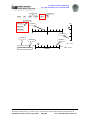
2.4.3
Report on System Status and
Position
The system turret status is reported on the image in the turret status field (upper
center image).
LOS attitude in azimuth and elevation is reported in degrees and as a tick mark
on the EL and AZ bars, plus the actual current reading of azimuth and elevation
(see figures 3-1).
2.4.4
INERTIAL Mode
To enable LOS slew, the system should be set into INERTIAL or HEADING HOLD
mode, by sending the proper commands via the serial link to the payload, or by
pressing on INRT/POS switch, on the HCG, INRT is display.
The legend INRT is on the turret status field.
If LOS rate is not commanded, the LOS will remain in its last position, but may
drift away slowly, according to the system natural drift.
When the system is calibrated, the drift is very slow and can be noticed only after
a few minutes.
2.4.4.1
Stabilization
In inertial mode, the LOS is stabilized (compensated) against external mechanical
disturbances. The LOS will point to an infinite point in the inertial space.
Movement of the carrying vehicle will not affect this pointing and the image will
appear stable on the display.
2.4.5
POSITION (Heading Hold) Mode
In Position mode the LOS is stabilized against external disturbances the same way
as in the inertial mode. However the LOS will maintain its position fixed, relative
to the carrying vehicle.
You may prevent the low drift, which may occur in the inertial mode, by changing
to HEADING HOLD (HH) mode. HHLD is display.
The INRT/POS is a toggle switch.
This document contains proprietary information of Israel Aircraft Industries Ltd. And may not be reproduced, copied,
disclosed or utilized in any way, in whole or in part, without the prior written consent of Israel Aircraft Industries Ltd.
POP200 User Manual. Rev #5, August 2004
Page 25
Doc: A-1346.0037.00.00-1756-4.05
P.O. BOX 75 Yehud 56100, Israel
Tel: +972 3 531 5350; Fax: +972 3 531 5138
2.4.6
STOW Position
Stow (STW)
This state is designed to keep the FLIR window safe by erecting the line of sight
upwards. Short press (less than 1 second) will bring the line of sight to elevation
of +90°, (azimuth to -180°) ,from any position. STOW legend is on the screen.
This position is maintained after system power down. A magnet "locks" the slice
unit opposite to the turret.
Exit from STOW by pressing shortly the INRT pushbutton and the system reaches
its last attitude before it was stowed, in azimuth and elevation.
For some users application, the magnet was removed and is not part of the
product configuration.
⌦ Note:
To stow up the LOS, keep short pressing toward IN - on the
turret mode pushbutton (STW). Long pressing will set the
system into non-uniformity correction mode.
In case that the system is using the FLIR optical magnifier (POP200M), than the
STOW position will be +15° in elevation and backwards.
This document contains proprietary information of Israel Aircraft Industries Ltd. And may not be reproduced, copied,
disclosed or utilized in any way, in whole or in part, without the prior written consent of Israel Aircraft Industries Ltd.
POP200 User Manual. Rev #5, August 2004
Page 26
Doc: A-1346.0037.00.00-1756-4.05
P.O. BOX 75 Yehud 56100, Israel
Tel: +972 3 531 5350; Fax: +972 3 531 5138
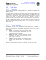
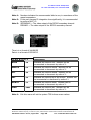
System
in Track
Elevation
Marker
Elevation
Bar
Track
Symbol
Elevation
Reading
Azimuth
Bar
Azimuth
Marker
Azimuth
Reading
Figure 3-1. System and Attitude Reports
This document contains proprietary information of Israel Aircraft Industries Ltd. And may not be reproduced, copied,
disclosed or utilized in any way, in whole or in part, without the prior written consent of Israel Aircraft Industries Ltd.
POP200 User Manual. Rev #5, August 2004
Page 27
Doc: A-1346.0037.00.00-1756-4.05
P.O. BOX 75 Yehud 56100, Israel
Tel: +972 3 531 5350; Fax: +972 3 531 5138
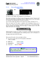
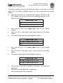
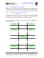
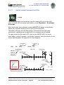
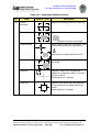
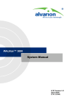
2.4.7
AUTO SCAN
2.4.7.1
General Description
Auto Scan (AS)
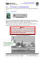
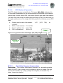
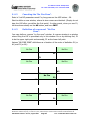
The AUTO SCAN mode is designed for automatic scanning of an area sector. The
scanning is a "window" scanning. The maximal scanning limits (maximal window)
are 180° in azimuth and 90° in elevation.
Push the turret mode button down (AS) to enter AS mode. You may exit auto
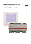
scan by forcing any other mode. Figure 4-1 describes a typical AutoScan pattern.
In AutoScan mode the LOS is stabilized against external disturbances the same
way as in Inertial mode.
⌦ Note
You may set the system to a very slow rate slew in
order to get a good distinction of the object in the
field of regard (FOR). Select the rate parameter as
required during the configuration of the rate.
2.4.7.2
Scanning Window and Velocity
The AS has a default (factory set) values of: ±20° in azimuth and ±20° in
elevation (both around 0°). The user may alter these values, see next.
Changing the zoom of the camera or FOV of the FLIR, while scanning causes a
change in scanning in such manner that the angular speed of the picture on the
screen stays constants.
During the scan there is 30% overlap in the FOV of the pass, between each
current pass of the scan and the previous pass of the scan. (pass = one snap of
left to right movement).
2.4.7.3
AS Window Configuration
The following instruct the user how to configure and select a new the AS window.
a.
Press the AS button for more than 3 seconds or rend the proper
commands via the serial link, for more than 3 seconds. This will enter the
system in AS configuration mode.
This document contains proprietary information of Israel Aircraft Industries Ltd. And may not be reproduced, copied,
disclosed or utilized in any way, in whole or in part, without the prior written consent of Israel Aircraft Industries Ltd.
POP200 User Manual. Rev #5, August 2004
Page 28
Doc: A-1346.0037.00.00-1756-4.05
P.O. BOX 75 Yehud 56100, Israel
Tel: +972 3 531 5350; Fax: +972 3 531 5138
b.
AS CFG text appears.
c.
Set first the upper right point of the scanned sector, using piloting
commands - Up/Down Left/Right.
d.
Press shortly on AS to store this point.
e.
Set next the down left point of the scanned sector using the piloting
pushbutton - bottom-right corner.
f.
Press shortly on AS to store this point.
g.
Determine the scanning velocity using the FT pushbutton upwards on
downwards (high speed or low speed).
h.
Press shortly on AS to accept this speed and to exit from CONFIG
position.
⌦ Note:
When referring here to buttons, it is also true for
sending the proper commands via the serial link.
The new set of, AS parameters are stored in the payload nonvolatile memory. It
will be used as new default after power cycling.
START
END
Figure 2-1. Autoscan Pattern
2.4.7.4
Exit from AS Mode.
Done by moving to any other working mode of the Payload: INERTIAL or
POSITION or non-uniformity correction.
This document contains proprietary information of Israel Aircraft Industries Ltd. And may not be reproduced, copied,
disclosed or utilized in any way, in whole or in part, without the prior written consent of Israel Aircraft Industries Ltd.
POP200 User Manual. Rev #5, August 2004
Page 29
Doc: A-1346.0037.00.00-1756-4.05
P.O. BOX 75 Yehud 56100, Israel
Tel: +972 3 531 5350; Fax: +972 3 531 5138
2.4.8
Cage Mode (Operator Window)
2.4.8.1
General Description, single CAGE
When selecting this mode, the line of sight moves to a pre defined LOS direction,
which is stored in the systems memory. The line of sight will not drift and will
always point towards this point. The FT is disabled.
You may configure the system CAGE pointing, to another direction (see next).
The CAGE pointing data is stored in the systems non-volatile memory. The default
CAGE pointing (factory set) is AZ = 0°, elevation -7° with reference to the payload
carrying plate.
Note: for some users application this value may be set at production, differently.
2.4.8.2
Using Operator Window Mode
Cage mode is used to bring the LOS at power up to a pre-known direction, or if,
during normal usage; the operator is loosing orientation (usually in the narrow
field) and wants to reach quickly to a known point.
2.4.8.3
Entering to Operator Window
Short press (less than 1 second) on the turret mode button, toward CG, or send
the proper commands via the serial link, will bring the line of sight to operator
window. CAGE legend appears on the image, in the system status area. In this
mode all the controls of the DTV and FLIR are active as usual.
2.4.8.4
CAGE Position Configuration
The following instruct the user how to configure and select the CAGE to new
pointing direction.
a.
Press the turret mode button CG position, for more than 3 seconds, or
send the proper commands via the serial link, for more than 3 seconds.
This will enter the system in CAGE configuration mode.
b.
CG CFG legend appears on the system status field.
c.
Determine the new required point of LOS, using piloting commands (or
HCG FT pushbutton) - Up/Down Left/Right.
d.
Press shortly on CAGE.
e.
The system exits CAGE CFG and new CG LOS is set.
This document contains proprietary information of Israel Aircraft Industries Ltd. And may not be reproduced, copied,
disclosed or utilized in any way, in whole or in part, without the prior written consent of Israel Aircraft Industries Ltd.
POP200 User Manual. Rev #5, August 2004
Page 30
Doc: A-1346.0037.00.00-1756-4.05
P.O. BOX 75 Yehud 56100, Israel
Tel: +972 3 531 5350; Fax: +972 3 531 5138
2.4.8.5
Exit from CAGE Mode
Done by moving to any other working mode of the Payload: INERTIAL or
POSITION or non-uniformity correction.
2.4.8.6
Triple CAGE, General Description
In some applications, the system can be configured to support three CAGEs. The
first time the user enters CG it will be CAGE-1. Any consecutive cage selection will
roll the next cage, which is CAGE-2 and then CAGE-3. The next selection of cage
will set the system to CAGE-1.
The default three CAGE pointing (factory set) with reference to the payload
carrying plate are:
CAGE-1 AZ = 0°, elevation -7°
CAGE-2 AZ = +90°, elevation -7°
CAGE-3 AZ = -90°, elevation -7°
Each one of the three cages may be configured to a new pre-defined LOS.
This document contains proprietary information of Israel Aircraft Industries Ltd. And may not be reproduced, copied,
disclosed or utilized in any way, in whole or in part, without the prior written consent of Israel Aircraft Industries Ltd.
POP200 User Manual. Rev #5, August 2004
Page 31
Doc: A-1346.0037.00.00-1756-4.05
P.O. BOX 75 Yehud 56100, Israel
Tel: +972 3 531 5350; Fax: +972 3 531 5138
2.5
2.5.1
Track Mode
Description
The real time video tracking mode is available only if this feature is installed in the
POP200 payload.
The video tracker processes the video signal output from the imaging sensor and
calculates LOS angular error relative to target location. In TRACK mode these
error signals are fed into the turret gimbals servo tracking loop witch nulls the
tracking errors via the gyro torquer. Hence the LOS of the FLIR or the DTV is
maintained on the target regardless of the carrying vehicle or the target motions.
In order to initiate video tracking, the target should have some contrast in its
details. The tracker is locked onto this contrast. If this contrast is too weak, than
track may be lost.
2.5.2
Tracker Submodes
The POP200 has basic track mode plus two track adjust modes. In addition if
track is lost than prediction mode enables the tracker to relock if track is lost for
few seconds.
¨
Track: If the tracker sense "enough" contrast of the
image, it tracks this target. (Maintain the LOS in the
center field of view of the image).
¨
Adjust: This mode enables the operator to move the
target track gate along the target in order to track
other points on the target.
¨
Search: This mode enables the operator to choose
another target without loosing the current tracking
target.
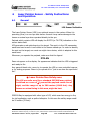
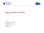
Figure 6-1 presents a typical track mode symbology. Note the track search.
This document contains proprietary information of Israel Aircraft Industries Ltd. And may not be reproduced, copied,
disclosed or utilized in any way, in whole or in part, without the prior written consent of Israel Aircraft Industries Ltd.
POP200 User Manual. Rev #5, August 2004
Page 32
Doc: A-1346.0037.00.00-1756-4.05
P.O. BOX 75 Yehud 56100, Israel
Tel: +972 3 531 5350; Fax: +972 3 531 5138
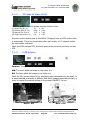
System in
Track Mode
Track
Symbol
Track Gate
and Point
Coincidence
This document contains proprietary information of Israel Aircraft Industries Ltd. And may not be reproduced, copied,
disclosed or utilized in any way, in whole or in part, without the prior written consent of Israel Aircraft Industries Ltd.
POP200 User Manual. Rev #5, August 2004
Page 33
Doc: A-1346.0037.00.00-1756-4.05
P.O. BOX 75 Yehud 56100, Israel
Tel: +972 3 531 5350; Fax: +972 3 531 5138
Track
Gate
Track Search
Mode
Track
Point
Track Cross moved
(Search) to Pre-lock
Point
Track Gate.
Track is on this
point
Figure 6-1. Typical Track Function Symbology
Note
The track point is always the center of the track window symbol.
This document contains proprietary information of Israel Aircraft Industries Ltd. And may not be reproduced, copied,
disclosed or utilized in any way, in whole or in part, without the prior written consent of Israel Aircraft Industries Ltd.
POP200 User Manual. Rev #5, August 2004
Page 34
Doc: A-1346.0037.00.00-1756-4.05
P.O. BOX 75 Yehud 56100, Israel
Tel: +972 3 531 5350; Fax: +972 3 531 5138
2.5.3
Track Mode - Selection and
Operation
To activate track mode, place the FLIR or DTV reticle on the target and press the
track button on the HCG or send the appropriate command via the uplink
communication.
a.
Normal Track: Hit the track button, if image is contrast enough, than
tracking is activated and track symbology appears. The gate size is
automatically adjusted to the target size.
b. Obscuration (Target Lost): If original target gets obscured,
than the tracker tries to predict where it may reappear by
continuing moving the LOS to that location. If within 6 seconds
target does not appear, than the system returns to inertial mode,
leaving the LOS at its last pointing direction.
c. Adjust: You may improve the track point for better reliability
(better contrast) by a fine adjustment of the tracking point
(crosshairs) on the target. Press the FT to move the tracker cross
hair to the new pointing. The tracker gate displays will blinking
and moved in direction as the pressure transducer reported, and
the tracker windows will follow with.
d. Search: While the system is in track mode, you may select a new
target to track on – without breaking lock on the current one.
¨
Press the track button for 3 seconds or more (or
send the proper command via the serial link)
until the legend TRCK SRC starts to blink, than
release the button. See figure 6-1.
¨
Next using the FT (or rate commands) mover the
track window on to the new target.
¨
Press again – shortly - on the track button. The
LOS will move to the new selected target and will
try to relock.
This document contains proprietary information of Israel Aircraft Industries Ltd. And may not be reproduced, copied,
disclosed or utilized in any way, in whole or in part, without the prior written consent of Israel Aircraft Industries Ltd.
POP200 User Manual. Rev #5, August 2004
Page 35
Doc: A-1346.0037.00.00-1756-4.05
P.O. BOX 75 Yehud 56100, Israel
Tel: +972 3 531 5350; Fax: +972 3 531 5138
⌦ Note:
The window size of the tracker may change during
track. The smaller the window is, the “quality” of the
tracking on the target is better.
2.5.4
Exiting Track Mode
Cancel track state by pressing the INT/POS button or transmitting the inertial
command to the payload. All other turret commands will not affect track mode.
2.5.5
Prediction Mode
The POP200 tracker has a build in prediction mode. If the object that is tracked
get obscured, or its contrast becomes too faint then the tracker tries to predict
how the object continues to move (relative to the LOS) and according to that, it’s
change the track gate symbol line to be a broken gate symbol line.
In parallel it continues to move the LOS hopping that "soon" the target will
reappear.
This process takes 6 seconds, if the target is found then the tracker re-locks,
otherwise it declares lost of target and lost track symbol will display.
Immediately after that the system will force itself to inertial mode, hence leaving
the track mode.
This document contains proprietary information of Israel Aircraft Industries Ltd. And may not be reproduced, copied,
disclosed or utilized in any way, in whole or in part, without the prior written consent of Israel Aircraft Industries Ltd.
POP200 User Manual. Rev #5, August 2004
Page 36
Doc: A-1346.0037.00.00-1756-4.05
P.O. BOX 75 Yehud 56100, Israel
Tel: +972 3 531 5350; Fax: +972 3 531 5138
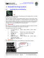
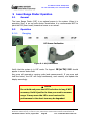
3 Controlling and Optimizing the Image Quality
All controls refer to the sensor, which was selected to be as a prime. They will
NOT have any effect on the other sensor.
3.1
3.1.1
FLIR Channel.
FLIR Focus
MFS
At the end of FLIR initialization, FLIR focus is set automatically to infinity. Press
shortly the focus button up or down, to go focus NEAR or FAR. (or by sending the
proper command via the uplink) to enable adjust the image to optimal focus. It is
recommended to press shortly and very gently, in order to develop sensitivity to
the change during focusing.
When you send the FLIR focus command, the Multi function Scale (MFS) will
appear for 6 seconds indicating the relative position of the focus.
3.1.2
Focus to Infinity.
Definition: The point at each FOV, where the image focuses on an average is
probably the best.
Press (or command) the FOCUS button IN. This will force the IR focus to move to
the infinity point and the DTV focus to tries again and refocus automatically.
3.1.3
FLIR Focus Memory.
FLIR focus position is memorized for each FOV. So when the user switches from
one FOV to the other, the focus for the newly selected FOV, goes automatically to
its previous position in that FOV.
This document contains proprietary information of Israel Aircraft Industries Ltd. And may not be reproduced, copied,
disclosed or utilized in any way, in whole or in part, without the prior written consent of Israel Aircraft Industries Ltd.
POP200 User Manual. Rev #5, August 2004
Page 37
Doc: A-1346.0037.00.00-1756-4.05
P.O. BOX 75 Yehud 56100, Israel
Tel: +972 3 531 5350; Fax: +972 3 531 5138
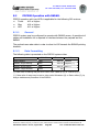
3.1.4
IR Fields Of Views (FOV)
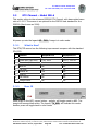
The FLIR image in POP200 system has four fields of view:
(1)
(2)
(3)
(4)
Wide FOV (H x V)
Medium FOV (H x V)
Narrow FOV (H x V)
Super Narrow (H x V)
22°
6.90°
1.72°
0.8°
x
x
x
x
16°
5.20°
1.29°
0.65°
At power up the system goes to the WFOV. Changing from one FOV to the other
is sequentially. There is a forced delay after each switch, of 1.5 seconds before
the next switch is allowed.
When the FLIR changes FOV, the focus goes to the previously set focus on that
FOV.
3.1.5
FLIR Polarity
Purpose: To select or modify the FLIR image polarity:
WH: The more white the image is, the hotter it is.
BH: The more black the image is, the hotter it is.
Press the HCG sensor button IN (or send the proper command from the host). It
is recommended to practice in different field scene images (especially at night) in
order to receive the optimal feeling on the proper POLARITY, to use.
White = Hot
Black = Hot
This document contains proprietary information of Israel Aircraft Industries Ltd. And may not be reproduced, copied,
disclosed or utilized in any way, in whole or in part, without the prior written consent of Israel Aircraft Industries Ltd.
POP200 User Manual. Rev #5, August 2004
Page 38
Doc: A-1346.0037.00.00-1756-4.05
P.O. BOX 75 Yehud 56100, Israel
Tel: +972 3 531 5350; Fax: +972 3 531 5138
3.1.6
FLIR Gain/Level Control.
MFS
Purpose: To allow the user to fine tune the FLIR image and depict certain
objects in the scene.
AUTO mode is the default mode after power up. In this mode the system
determines by itself the values of GAIN and LEVEL of the FLIR camera to optimal
values. The operator can improve the image, by entering into a MANUAL mode.
Change to MANUAL by pressing shortly on the AGC button IN. Verify the legend
MAN appears on the FLIR status area.
Press shortly on the GN or LV pushbutton towards up or down, as required on the
HCG (or send the proper commands on the uplink to the payload).
When the operator attempt to change the gain or level, manually, the Multi
function Scale (MFS) will appear for 10 seconds indicating the relative position of
the associated parameter.
⌦ Note
Using GAIN LEVEL mode requires some experience by the
operator, and it is recommended that only a skilled operator
will use it.
Transition between automatic and manual modes:
a.
When changing FLIR tables – always return to automatic G/L.
b.
When changing to manual in the same FLIR FOV, the system returns
automatically to previous values (history) of GAIN LEVEL values.
c.
When in manual mode and changing fields – the new FOV will be at
AUTO GAIN.
( Tip: After you go to manual mode, try first the GAIN UP (or down) for
better results. Only then change the level.
This document contains proprietary information of Israel Aircraft Industries Ltd. And may not be reproduced, copied,
disclosed or utilized in any way, in whole or in part, without the prior written consent of Israel Aircraft Industries Ltd.
POP200 User Manual. Rev #5, August 2004
Page 39
Doc: A-1346.0037.00.00-1756-4.05
P.O. BOX 75 Yehud 56100, Israel
Tel: +972 3 531 5350; Fax: +972 3 531 5138
3.1.7
FLIR Semi Automatic AGC
Purpose: To allow the user to fine tune the FLIR image in environment where
the background changes rapidly.
FLIR Semi Automatic AGC: This mode is applicable for slice SW version #16 or
higher.
In this mode the GAIN is controlled manually, while the LEVEL is set automatically
by the system. Enter this mode, using a short press on the GAIN UP. The legend
AE_GAIN appears on the FLIR status field.
Exit this mode to full auto by a short press on the AGC button IN. Verify the
legend AUTO appears on the FLIR status area.
3.1.8
Freeze the FLIR Image.
FZ
Purpose:
To enable the user to freeze a dynamic scene, in order to
investigate in more details a certain event or dynamic target.
Operation:
Press shortly on the HCG, the sensor button FZ position
(right). This action will freeze the FLIR image on the display. FREEZE legend
appears on the FLIR status field.
To release the freeze, press shortly again on the FZ button.
Note that in FREEZE mode the Tracker, Laser pointer and the LRF functions, are
disabled.
This document contains proprietary information of Israel Aircraft Industries Ltd. And may not be reproduced, copied,
disclosed or utilized in any way, in whole or in part, without the prior written consent of Israel Aircraft Industries Ltd.
POP200 User Manual. Rev #5, August 2004
Page 40
Doc: A-1346.0037.00.00-1756-4.05
P.O. BOX 75 Yehud 56100, Israel
Tel: +972 3 531 5350; Fax: +972 3 531 5138
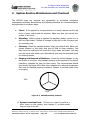
3.1.9
Non-uniformity Tables
Replacement
TBL
Purpose: To select (or change) FLIR uniformity tables.
For details on NUC tables, see paragraph 8 in this document.
Each table is optimized to a different range of temperature scenes. You may scroll
among the three tables by pressing shortly the MENU button to the TBL position
(or sending to the payload uplink the proper command)
(You may also select each table via the system menu option, see Figure 10-1).
When you select the TBL option, a question will be displayed, asking you to
confirm your request. Ignoring the question will leave the current selected table,
and the question will disappear from the image. A second press on the TBL
button will scroll to the next table.
CHANGE TBL ?
Default selection at power up is table #1 referred to as WARM. You may view the
current table, by scrolling between the symbology layers, until it will appear on
the upper right side of the FLIR image.
Each press will transfer to the next table as follow:
¨
At power-up and when the FLIR completes initialization:
Table #1, WARM.
¨
First click:
Table #2 COOL
¨
Second click:
Table #3 COLD
¨
Next click:
Table #1 WARM.
⌦ Note
Under normal FLIR operation, there is no need to
change uniformity tables
This document contains proprietary information of Israel Aircraft Industries Ltd. And may not be reproduced, copied,
disclosed or utilized in any way, in whole or in part, without the prior written consent of Israel Aircraft Industries Ltd.
POP200 User Manual. Rev #5, August 2004
Page 41
Doc: A-1346.0037.00.00-1756-4.05
P.O. BOX 75 Yehud 56100, Israel
Tel: +972 3 531 5350; Fax: +972 3 531 5138
Table exchange may be considered only in a case of
extreme changing of the background temperature
scene, such as transition between day and night.
This document contains proprietary information of Israel Aircraft Industries Ltd. And may not be reproduced, copied,
disclosed or utilized in any way, in whole or in part, without the prior written consent of Israel Aircraft Industries Ltd.
POP200 User Manual. Rev #5, August 2004
Page 42
Doc: A-1346.0037.00.00-1756-4.05
P.O. BOX 75 Yehud 56100, Israel
Tel: +972 3 531 5350; Fax: +972 3 531 5138
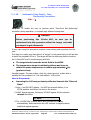
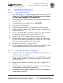
3.1.10
Automatic (One Point) – Non
Uniformity Correction.
STW----
Purpose: To enable the user to perform quick “One-Point Non-Uniformity”
correction during operation, in a simple way without loosing time.
µ Caution !
Before performing this 1-Point NUC, be sure you do
understand how this procedure affect the image, and what
you expect to get afterwards.
In any case using this procedure requires some training and expertise from the
user.
First step is to make sure that there is a “target” in the scene that you will be able
to point the payload LOS to it. This target will be the reference plate to perform
the 1-Point NUC and it should comply with this:
a. The target should cover the whole field in the NFOV.
b. The temperature target is relatively uniform and close to
within the scene temperature to within approximately ±10°
(preferred less).
Possible targets: The sea surface, clear sky, desert ground, a plate that is
installed for this purpose in a “not used section” of the view.
Here is the process:
a.
Assuming the LOS was previously calibrated towards the “External
Plate”.
1.Press – and DO NOT release - the HCG turret mode button, in to
STOW position and follow the text on the screen.
2.A NUC legend appears, follows by AT NUC legend. At this moment
release the button.
AT NUC
3.The 1-POINT NUC process starts and proceeds all the way
automatically. Note that when the LOS reaches its target position,
additional legend appears:
This document contains proprietary information of Israel Aircraft Industries Ltd. And may not be reproduced, copied,
disclosed or utilized in any way, in whole or in part, without the prior written consent of Israel Aircraft Industries Ltd.
POP200 User Manual. Rev #5, August 2004
Page 43
Doc: A-1346.0037.00.00-1756-4.05
P.O. BOX 75 Yehud 56100, Israel
Tel: +972 3 531 5350; Fax: +972 3 531 5138
AT NUC
A NUC POS
This document contains proprietary information of Israel Aircraft Industries Ltd. And may not be reproduced, copied,
disclosed or utilized in any way, in whole or in part, without the prior written consent of Israel Aircraft Industries Ltd.
POP200 User Manual. Rev #5, August 2004
Page 44
Doc: A-1346.0037.00.00-1756-4.05
P.O. BOX 75 Yehud 56100, Israel
Tel: +972 3 531 5350; Fax: +972 3 531 5138
4.At the end the system LOS returns to its initial position with the initial
FOV and focus.
b.
Assuming the LOS was NOT calibrated towards the “External
Plate”.
1.Press – and DO NOT release - the HCG turret mode button, in to
STOW position and follow the text on the screen.
2.A NUC legend appears, follows by AT NUC legend, followed by NUC
POS CFG. At this moment release the button.
AT NUC
NUC POS CFG
3.Go the WFOV or MFOV so will be able to find easily the target.
4.Now, use the FT to slew the LOS to the selected “target” scene. Set
the target at the center FOV
5.Once the LOS is on the “target scene”, go back NARROW FOV. Now
the system is ready to continue the process
6.Press shortly on the STOW button IN – to complete the process.
7.The “external 1 - POINT NUC” process starts and proceeds all the
way automatically. Note the legend:
AT NUC
AT NUC POS
8.Also the LOS that you have selected will be stored for future
corrections, as a default direction.
9.At the end the system LOS returns to its initial position with the initial
FOV and focus.
Notes:
a.
The default (factory set) direction for this process is elevation
0° and azimuth 180° (back of the payload).
b.
The new selected LOS data above, (item 5) is stored in the
nonvolatile memory for any next operation (as a new
calibration of CAGE LOS).
This document contains proprietary information of Israel Aircraft Industries Ltd. And may not be reproduced, copied,
disclosed or utilized in any way, in whole or in part, without the prior written consent of Israel Aircraft Industries Ltd.
POP200 User Manual. Rev #5, August 2004
Page 45
Doc: A-1346.0037.00.00-1756-4.05
P.O. BOX 75 Yehud 56100, Israel
Tel: +972 3 531 5350; Fax: +972 3 531 5138
3.2
DTV Channel – for POP Models 200
This section refers to the standard POP200 DTV Channel, with base optical zoom ratio of
1:16
3.2.1
DTV Focus.
DTV Manual Focus
The TV focus is set automatically at the end of each zooming. The user may
manually control the focus to FAR or NEAR. Click on the FOCUS button to FAR or
NEAR. From this point and on, the TV focus remains in manual.
Transition back to auto focus is made when the user zooms again the DTV, or
press shortly the FOCUS button IN to go to “focus to infinity”.
⌦ Note
DTV focus is set automatic at the end of each zoom.
Once the DTV focus is set, it will not tries to refocus
if the scene has changed - unless the user zooms, or
a “focus to infinity” is commanded.
Figure 3.2-1 typical DTV 200 image
HAND (POP200): Indicates
that TV zoom or focus
were selected
This document contains proprietary information of Israel Aircraft Industries Ltd. And may not be reproduced, copied,
disclosed or utilized in any way, in whole or in part, without the prior written consent of Israel Aircraft Industries Ltd.
POP200 User Manual. Rev #5, August 2004
Page 46
Doc: A-1346.0037.00.00-1756-4.05
P.O. BOX 75 Yehud 56100, Israel
Tel: +972 3 531 5350; Fax: +972 3 531 5138
3.2.2
DTV Zoom.
TV ZOOM Indicator
The DTV image, has a continues optical zoom of ratio 1:16 and additional
electronic magnification of X32. (in this mode an ELZM legend appears to
indicate a position of electronic zoom).
When the operator attempts to change the DTV zoom, manually, the Multi
function Scale (MFS) will appear for 10 seconds indicating the relative position of
the zoom accompanied with a number of the actual zoom relative to the wide,
being as 1.
3.2.3
DTV - Shutter Speed Control.
TV Shutter Speed indicator
The TV shutter speed can be adjusted with the GAIN up/down button. When you
select this option the actual value of the exposure speed will appear on the
image.
The values are: 1/60 of a second, which is the default, and consecutives values
till 1/10,000 of a second. Note that any selected value will be memorize by the
system and will be used for the next system power up.
If the default value is not the selected one, than each time the user zoom the
DTV, the actual value will appear on the DTV image.
This document contains proprietary information of Israel Aircraft Industries Ltd. And may not be reproduced, copied,
disclosed or utilized in any way, in whole or in part, without the prior written consent of Israel Aircraft Industries Ltd.
POP200 User Manual. Rev #5, August 2004
Page 47
Doc: A-1346.0037.00.00-1756-4.05
P.O. BOX 75 Yehud 56100, Israel
Tel: +972 3 531 5350; Fax: +972 3 531 5138
3.3
DTV Channel – Model 200-6
This section refers to the enhanced POP200 DTV Channel, with base optical zoom
ratio of 1:22.5. This sensor is an optional for the POP200 and standard for the
POP300 (Also known as 200A).
At power up note the legend AE – FULL. Image is in color mode.
3.3.1
What is New?
This DTV/CCD sensor has the following improvement compare with the standard
DTV/CCD
Feature
Standard DTV
Enhanced DTV
1
Sensor
1/4“
1/6”
2
Zoom ratio (Opt, Elec)
1:16, 16:32
1:22.5, 22.5:45
3
Focus Auto, Man
Yes
Yes
4
Near IR
No
Yes
5
Full Auto
No
Yes
6
Shutter Pri
Yes
Yes
7
IRIS Pri
No
Yes
8
Full Manual
No
Yes
9
Image Freeze
No
Yes
3.3.2
Near IR
PLR
Short press on the HCG, sensor button – polarity, will toggle mode to NIR. The
image will become black-white. The legend TV_NIR will indicate this mode.
Another press will toggle back to color mode.
This document contains proprietary information of Israel Aircraft Industries Ltd. And may not be reproduced, copied,
disclosed or utilized in any way, in whole or in part, without the prior written consent of Israel Aircraft Industries Ltd.
POP200 User Manual. Rev #5, August 2004
Page 48
Doc: A-1346.0037.00.00-1756-4.05
P.O. BOX 75 Yehud 56100, Israel
Tel: +972 3 531 5350; Fax: +972 3 531 5138
3.3.3
DTV Focus.
The TV focus is set automatically at the end of each zooming. The user may
manually control the focus to FAR or NEAR. Click on the FOCUS button to FAR or
NEAR. From this point and on, the TV focus remains in manual.
Transition back to auto focus is made when the user zooms again the DTV, or
press shortly the FOCUS button IN to go to “focus to infinity”.
When in manual focus, the legend MAN-FOC appears on the upper right corner
of the image.
3.3.4
DTV Zoom.
TV ZOOM Indicator
The DTV image, has a continues optical zoom of ratio 1:22.5 and additional
electronic magnification of X45. (In this mode an ELZM legend appears to
indicate a position of electronic zoom).
Press and hold the HCG FOV button to control the zoom. Each press will causes
the zoom status bar to appear. It will stay for 6 seconds after you release the FOV
button.
The DTV zoom bar acts like an MSF bar. The actual zoom marker position runs
from left (OPTICAL X1) to the center (OPTICAL X22) and to the right
(ELECTRICAL X45).
3.3.5
Freeze the DTV Image.
FZ
Purpose:
To enable the user to freeze a dynamic scene, in order to
investigate in more details a certain event or dynamic target.
Operation:
Press shortly on the sensor button of the HCG, to FZ position
(right). This action will freeze the DTV image on the display.
This document contains proprietary information of Israel Aircraft Industries Ltd. And may not be reproduced, copied,
disclosed or utilized in any way, in whole or in part, without the prior written consent of Israel Aircraft Industries Ltd.
POP200 User Manual. Rev #5, August 2004
Page 49
Doc: A-1346.0037.00.00-1756-4.05
P.O. BOX 75 Yehud 56100, Israel
Tel: +972 3 531 5350; Fax: +972 3 531 5138
FREEZE legend appears on the FLIR status field. To release the freeze, press
shortly again on the FZ button.
Note that in FREEZE mode the Tracker, Laser pointer and the LRF functions, are
disabled.
Figure 3.3-1 typical DTV 300 (200A) image
TV Mode: COLOR
or NIR
Focus status
DTV Exposure mode
Focus bar
Electronic ZOOM
indicator
ZOOM ratio Value
ZOOM indicator bar
This document contains proprietary information of Israel Aircraft Industries Ltd. And may not be reproduced, copied,
disclosed or utilized in any way, in whole or in part, without the prior written consent of Israel Aircraft Industries Ltd.
POP200 User Manual. Rev #5, August 2004
Page 50
Doc: A-1346.0037.00.00-1756-4.05
P.O. BOX 75 Yehud 56100, Israel
Tel: +972 3 531 5350; Fax: +972 3 531 5138
3.3.6
DTV Modes of Operation
The DTV default at power up is full auto. The legend AE – FULL indicates this.
In this mode all parameters of the camera settings are controlled by the camera
internal logic: Shutter speed, IRIS, over/under exposure, gain and White balance.
You may at any time scroll the image layers and bring up the DTV status field, on
the upper right portion of the image; this field presents the following current DTV
data:
Shutter speed in tenth of a seconds:
1/10,000
IRIS in F ratio number: F1.6 to F28.
Zoom in relative ratio: X1 to X45.
FOV in milliradianns:
380 to 8.5
1/15
(1/12
PAL)
to
DTV Status
Field
Figure 3.3-2 Typical DTV status field display (300, 200A) image
DTV mode of
Operation
3.3.6.1
Over/Under Exposure Compensation
Description: This function shifts slightly (manually) the automatic operating
point of the DTV (gain, shutter, iris) to brighten or darken the image. You may
increase the exposure by 7 steps, (image more brighter) or decrease it by 7
steps, (image more darker)
This document contains proprietary information of Israel Aircraft Industries Ltd. And may not be reproduced, copied,
disclosed or utilized in any way, in whole or in part, without the prior written consent of Israel Aircraft Industries Ltd.
POP200 User Manual. Rev #5, August 2004
Page 51
Doc: A-1346.0037.00.00-1756-4.05
P.O. BOX 75 Yehud 56100, Israel
Tel: +972 3 531 5350; Fax: +972 3 531 5138
Purpose:
To “fine tune” the image. To control image quality while the
camera is still in full auto mode.
Operation:
This mode is operational only when the DTV is in AE – FULL.
Short press (Less than 1 second) on the GAIN UP, will enter to this mode. To
increase exposure, click the GAIN up. To decrease exposure, click the GAIN down.
Exit this mode by short press on the GAIN – to IN.
Status display:
In the status field, EXP – COMP. In the DTV status field,
see the line COPM +/- #, indicates the value of over/under compensation: 7 steps
up, and 7 steps down.
B
Tip
Use the image brightness to decide which is the best
exposure to use. Under standard conditions, the camera
selects the best exposure.
3.3.6.2
Shutter Speed Priority.
Description: Select and control the shutter speed of the camera, refer to also
as shutter priority mode. You may select values from 1/15 second (image
brighter) up to 1/10,100 second (image darker).
Purpose:
To have the shutter speed fixed and controlled by the user.
Operation:
When enter to this mode, the shutter speed is fix and the user
selects its value. Long press (3 seconds) on the GAIN UP, will enter to this mode.
You may enter this mode while the DTV is in AE full or in IRIS priority modes.
To increase speed, click the GAIN up. To decrease speed, click the GAIN down.
Exit this mode by short press on the GAIN – to IN.
Status display:
In the status field (upper left portion of the display), AE SHTR. In the DTV status field, see the line SHTR #, indicates the value of the
speed.
The first entry value of the shutter speed is the current speed in auto.
This document contains proprietary information of Israel Aircraft Industries Ltd. And may not be reproduced, copied,
disclosed or utilized in any way, in whole or in part, without the prior written consent of Israel Aircraft Industries Ltd.
POP200 User Manual. Rev #5, August 2004
Page 52
Doc: A-1346.0037.00.00-1756-4.05
P.O. BOX 75 Yehud 56100, Israel
Tel: +972 3 531 5350; Fax: +972 3 531 5138
Figure 3.3-3 Shutter Priority DTV 300 (200A) image
Shutter
speed value
Shutter speed
Priority mode
B
Tip
Increase speed when the image looks too bright.
3.3.6.3
IRIS Priority.
Description: Select and control the IRIS of the camera, refer to also as IRIS
priority mode. You may select values from F1.6 (image brighter) up to F28 (image
darker).
Purpose:
To have the IRIS fixed and controlled by the user.
Operation:
When enter to this mode, the IRIS is fix and the user selects its
value. Long press (3 seconds) on the LEVEL UP, will enter to this mode. You may
enter this mode while the DTV is in AE full or in Shutter speed priority modes.
To increase (close) IRIS, click the LEVEL up. To decrease (close), click the LEVEL
down. Exit this mode by short press on the GAIN – to IN.
This document contains proprietary information of Israel Aircraft Industries Ltd. And may not be reproduced, copied,
disclosed or utilized in any way, in whole or in part, without the prior written consent of Israel Aircraft Industries Ltd.
POP200 User Manual. Rev #5, August 2004
Page 53
Doc: A-1346.0037.00.00-1756-4.05
P.O. BOX 75 Yehud 56100, Israel
Tel: +972 3 531 5350; Fax: +972 3 531 5138
Status display:
In the status field (upper left portion of the display), AE IRIS. In the DTV status field, see the line IRIS F#, indicates the value of the
IRIS.
The first entry value of the IRIS is the current IRIS in auto.
Figure 3.3-3 IRIS Priority DTV 300 (200A) image
IRIS value
IRIS Priority
mode
B
Tip
Increase IRIS (more of the F) when the image looks too
bright.
3.3.6.4
Full Manual mode
Use of this function by expert user only.
Purpose: To enable the user to have a full control on the shutter speed and the
IRIS.
This document contains proprietary information of Israel Aircraft Industries Ltd. And may not be reproduced, copied,
disclosed or utilized in any way, in whole or in part, without the prior written consent of Israel Aircraft Industries Ltd.
POP200 User Manual. Rev #5, August 2004
Page 54
Doc: A-1346.0037.00.00-1756-4.05
P.O. BOX 75 Yehud 56100, Israel
Tel: +972 3 531 5350; Fax: +972 3 531 5138
Description: In this mode the user can set the shutter speed from 1/30 to
1/10,000 and IRIS from F1.6 to F28 (next click will close the IRIS).
Operation:
Short press on the AGC button IN will set the system to full
manual mode. Next press on AGC will return the DTV to auto.
Status display:
In the status field (upper left portion of the display), MAN .
In the DTV status field, see the line IRIS F#, indicates the value of the IRIS.
The DTV status sub field – comes up automatically, and presents two lines of
actual data:
Shutter speed in tenth of a seconds:
1/15
(1/12
PAL)
to
1/10,000
IRIS in F ratio number: F1.6 to F28.
Figure 3.3-3 Manual DTV 300 (200A) image
DTV Status
DTV Manual
µ
Caution
You may set accidentally the IRIS and the SPEED to
values, which will cause the DTV image to disappear
(Bright or dark image). If so, press shortly the AGC
button, to revert to FULL AUTO
This document contains proprietary information of Israel Aircraft Industries Ltd. And may not be reproduced, copied,
disclosed or utilized in any way, in whole or in part, without the prior written consent of Israel Aircraft Industries Ltd.
POP200 User Manual. Rev #5, August 2004
Page 55
Doc: A-1346.0037.00.00-1756-4.05
P.O. BOX 75 Yehud 56100, Israel
Tel: +972 3 531 5350; Fax: +972 3 531 5138
4 Manipulate the Image symbols.
4.1
Symbology Layers Modification
SYM
Purpose: To control the amount of symbology and information which is overlaid
on the image at a certain time.
You may clutter or declutter the symbologyl layers that are on the screen. When
there is a need to remove symbology or a certain segment in the symbology, that
covers important details of the area. It is possible also to remove all the symbols
from the screen. The symbology appears as 5 layers that can be removed from
the screen, one by one, according to the following order.
a. Direct Scroll
Each click on the sensor pushbutton down (SYM) will remove one layer at a time
(or by sending the command on the uplink from the host).
The layers removal order list is as follow:
1.
At system power-up:
and TOD.
Reticle, angle markers, system status
2.
First click leaves:
Attitude bars, system status and TOD.
3.
Second click:
Without any symbol on the image.
4.
Third click:
Reticle only.
5.
Forth click leaves:
TOD and FLIR status.
Reticle, attitude bars, system status
6.
Next click, returning to (1).
b. Menu Scroll
You may also scroll the layers, via the MENU layer status line as follows:
Scroll this line to
change layers
This document contains proprietary information of Israel Aircraft Industries Ltd. And may not be reproduced, copied,
disclosed or utilized in any way, in whole or in part, without the prior written consent of Israel Aircraft Industries Ltd.
POP200 User Manual. Rev #5, August 2004
Page 56
Doc: A-1346.0037.00.00-1756-4.05
P.O. BOX 75 Yehud 56100, Israel
Tel: +972 3 531 5350; Fax: +972 3 531 5138
4.2
Symbology Hue Modification
HUE
Purpose: To control hue of the symbology, so it will not fade away in a certain
background.
Hue modification is done as follows:
a. Using the MENU button, click up to HUE. The hue will change sequentially.
Selecting hue this way will leave the payload hue at power up at its default,
or:
b. Through the POP200 MENU option by scrolling the first line item. In this
case the user can see the hue on a sample "A" letter, before actual
execution. Using this option requires user approval “SAVE”. Next power up
will be using the last selected HUE.
Six different hues are available.
Order
Test color
Text background
1
White
Grey
2
White
None
3
Black
None
4
Grey
White
5
Grey
None
6
Black
White
Select SAVE to
accept your
selection
The selected
symbol HUE
This document contains proprietary information of Israel Aircraft Industries Ltd. And may not be reproduced, copied,
disclosed or utilized in any way, in whole or in part, without the prior written consent of Israel Aircraft Industries Ltd.
POP200 User Manual. Rev #5, August 2004
Page 57
Doc: A-1346.0037.00.00-1756-4.05
P.O. BOX 75 Yehud 56100, Israel
Tel: +972 3 531 5350; Fax: +972 3 531 5138
4.3
Modify Azimuth Reading.
MAN----
Purpose: To enable the AZ reading to refer to a known azimuth, typically the
north.
This mode is available only for systems, which does NOT carry the LRF sensor.
How to set this reading?
1.Point the LOS toward the target, which its AZIMUTH value is known.
2.Press IN, a long press on the HCG AUT/MAN button about 3 seconds
until a legend SET NORTH will appear on the display.
3.Notice that the Az = XY.Z legend on the right bottom, becomes
AzN = XY.Z
4.Now use the GAIN position UP or DOWN to increase or decrease the
AZ reading (XY.Z in this example) on the bottom right of the display,
so it will read the absolute azimuth of the known target the LOS
points at.
How to leave setup mode ?
To leave the setup mode – press again the G/L in, while there two ways to do so:
a. Short press: Will leave the new AzN reading for this session of system
operation. After power recycling the azimuth reading will refer to the mechanical
installation as normal and the recorded AzN data from the past will be lost.
b. Long press:
Will leave the new AzN reading for this session of
system operation. After power recycling the azimuth reading will refer to the
mechanical installation as normal. However the recorded AzN data will be stored
in the turret nonvolatile memory for future use.
Now the azimuth reading will refer to this selected point.
This document contains proprietary information of Israel Aircraft Industries Ltd. And may not be reproduced, copied,
disclosed or utilized in any way, in whole or in part, without the prior written consent of Israel Aircraft Industries Ltd.
POP200 User Manual. Rev #5, August 2004
Page 58
Doc: A-1346.0037.00.00-1756-4.05
P.O. BOX 75 Yehud 56100, Israel
Tel: +972 3 531 5350; Fax: +972 3 531 5138
µ Caution:
Do not move the payload from its current position, after performing
AzN, other wise this reading will become meaningless.
How to deselect AzN mode ?
a.
Power recycle will bring the system to normal azimuth display. Or
b.
While in AzN mode, long Press as describe above, will bring the SET AZ
NORTH on the upper screen. While this legend is on pres again shortly IN on the
HCG AUT/MAN button. This will cancel the AzN mode.
This document contains proprietary information of Israel Aircraft Industries Ltd. And may not be reproduced, copied,
disclosed or utilized in any way, in whole or in part, without the prior written consent of Israel Aircraft Industries Ltd.
POP200 User Manual. Rev #5, August 2004
Page 59
Doc: A-1346.0037.00.00-1756-4.05
P.O. BOX 75 Yehud 56100, Israel
Tel: +972 3 531 5350; Fax: +972 3 531 5138
5 Laser Range Finder Operation
5.1
General
The Laser Range Finder (LRF) is an optional sensor in the system. When it is
operating (fires) is an eye safe device. Nevertheless it is recommended NOT to
point the LOS (laser beam) towards a human or an animal.
5.2
5.2.1
Operation
Ranging
LRF Sensor Indication
Figure 5-1 HCG, LSR button
Verify that the system is in LRF mode. The legend IR (or TV) – LRF should
appear in sensor status field.
Any press will generate a ranging pulse (and measurement). If you press and
hold the button, the LRF will range continuously, each second, and update the
display accordingly.
µ Caution
Do not hold and press the LRF Fire button to long if NOT
necessary. Hold it just for the time you need to measure
range. It may cause the LRF to over heat and its
performance in the short term may be degraded.
This document contains proprietary information of Israel Aircraft Industries Ltd. And may not be reproduced, copied,
disclosed or utilized in any way, in whole or in part, without the prior written consent of Israel Aircraft Industries Ltd.
POP200 User Manual. Rev #5, August 2004
Page 60
Doc: A-1346.0037.00.00-1756-4.05
P.O. BOX 75 Yehud 56100, Israel
Tel: +972 3 531 5350; Fax: +972 3 531 5138
5.2.2
When Ranging is Allowed.
Ranging is possible only in the following modes:
Inertial, Position or tracking.
Ranging will NOT be activated if the payload is in one of the following modes:
¨ Standby or slice initialization (SINI) or turret initialization (TINI).
¨ CAGE, AUTOSCAN or image FREEZE.
¨ Nun uniformity correction or system backup
Also ranging will NOT be allowed when you point into the “ranging forbidden
zone” – if a zone was selected.
This document contains proprietary information of Israel Aircraft Industries Ltd. And may not be reproduced, copied,
disclosed or utilized in any way, in whole or in part, without the prior written consent of Israel Aircraft Industries Ltd.
POP200 User Manual. Rev #5, August 2004
Page 61
Doc: A-1346.0037.00.00-1756-4.05
P.O. BOX 75 Yehud 56100, Israel
Tel: +972 3 531 5350; Fax: +972 3 531 5138
5.2.3
Range Display
Immediately after fire you may get the following result:
M:
If the LRF encounter several echos.
Number (meters) indicating the range.
F / L:
Indicates that the range relates to the First echo or Last echo.
Range data is displayed for limited time: 5, or 10, or 20 seconds (depending on a
maintenance setup selection)
Range result
Range on the
First Echo
Multiple
targets
Range results
This document contains proprietary information of Israel Aircraft Industries Ltd. And may not be reproduced, copied,
disclosed or utilized in any way, in whole or in part, without the prior written consent of Israel Aircraft Industries Ltd.
POP200 User Manual. Rev #5, August 2004
Page 62
Doc: A-1346.0037.00.00-1756-4.05
P.O. BOX 75 Yehud 56100, Israel
Tel: +972 3 531 5350; Fax: +972 3 531 5138
5.2.4
Setting LRF parameters
MAN----
LRF RG Setting
Purpose
This section explains how to set LRF parameters:
¨ Minimum range
¨ Maximum range
¨ Select the First (F) or Last (L) echo to use as a target.
On the HCG press and hold the AGC button IN, for 3 seconds or more. The status
of the current Min Max range gates and F/L echo will appear on the bottom of the
image.
Current RG
Settings
1.
By clicking up or down the GAIN, you change the minimum range
value.
2.
By clicking up or down the LEVEL, you change the maximum range
value. (Short press will increase by 100 meters and long by 1000
meters).
3.
By clicking in the GAIN, you toggle the selection of F / L value.
4.
To store these values, exit this mode by LRF firing, press LSR.
5.
Or if you wish NOT to store, than press inside the AGC button.
This document contains proprietary information of Israel Aircraft Industries Ltd. And may not be reproduced, copied,
disclosed or utilized in any way, in whole or in part, without the prior written consent of Israel Aircraft Industries Ltd.
POP200 User Manual. Rev #5, August 2004
Page 63
Doc: A-1346.0037.00.00-1756-4.05
P.O. BOX 75 Yehud 56100, Israel
Tel: +972 3 531 5350; Fax: +972 3 531 5138
These values are stored in the system non-volatile memory, for future use, also
after power recycle.
5.3
Ranging Fail
There are several cases when range results are not available:
a.
In case that the LRF was not able to get echo. In this case the data that will
be displayed in null:
No range
Echo
b.
Firing into a NO FIRE ZONE. “NO FIRE” flashes.
c.
If the LRF was not able to generate a pulse, or the operator fires into a no
fire zone, than the legend NO FIRE will appear for several seconds.
5.4
5.4.1
No Fire Zones Window
Setting and Update the “No Fire
Zones” Window.
The following describes step by step, how to define a “no fire zone” (window).
Application: No fire zone is useful when you know for sure that if you fire the
LRF to this direction, its beam may hit a known object and reflects back towards a
person walking by.
When you set this window, its value remains in the system non-volatile memory.
When you turn off and back to on the payload, it will continue using the last set
window. (Same logic as for the logic for setting the auto scan window).
This document contains proprietary information of Israel Aircraft Industries Ltd. And may not be reproduced, copied,
disclosed or utilized in any way, in whole or in part, without the prior written consent of Israel Aircraft Industries Ltd.
POP200 User Manual. Rev #5, August 2004
Page 64
Doc: A-1346.0037.00.00-1756-4.05
P.O. BOX 75 Yehud 56100, Israel
Tel: +972 3 531 5350; Fax: +972 3 531 5138
To define a window, enter the LRF range gate setup by long press on the AGC
button IN. If the data of MIN/MAX appear you may proceed with the window
setting.
a.
Press the AS button for 3 seconds until a legend FZ CFG (or AS
CFG) appears on the turret field and the following appears on the
bottom of the screen.
FIRE ZONE CFG
P1
b.
Now, slew the LOS to the upper left corner of your desired
window.
c.
When the LOS on the proper point, press shortly the AS button
(down).
d.
The window status legend will be updated as follows:
FIRE ZONE CFG
P1 AZ = 157.9 EL = - 0.7
P2
e.
Now, slew the LOS to the lower right corner of your desired
window.
f.
When the LOS on the proper point, press shortly the AS button
(down).
g.
The window status legend will be updated as follows:
FIRE ZONE CFG
P1 AZ = 157.9 EL = - 0.7
P2 AZ = 167.3 EL = 1.4
h.
Press shortly on the AS to complete the process. The dialog box
disappears.
i.
Press shortly on the INERTIAL to enable slew.
j.
Now the process has been completed.
This document contains proprietary information of Israel Aircraft Industries Ltd. And may not be reproduced, copied,
disclosed or utilized in any way, in whole or in part, without the prior written consent of Israel Aircraft Industries Ltd.
POP200 User Manual. Rev #5, August 2004
Page 65
Doc: A-1346.0037.00.00-1756-4.05
P.O. BOX 75 Yehud 56100, Israel
Tel: +972 3 531 5350; Fax: +972 3 531 5138
You may abort this process at any time, without its completion, by simply
pressing shortly the MENU button, in.
Note: Figures above are for reference only. These numbers are referred to the
POP200 central line of sight.
This document contains proprietary information of Israel Aircraft Industries Ltd. And may not be reproduced, copied,
disclosed or utilized in any way, in whole or in part, without the prior written consent of Israel Aircraft Industries Ltd.
POP200 User Manual. Rev #5, August 2004
Page 66
Doc: A-1346.0037.00.00-1756-4.05
P.O. BOX 75 Yehud 56100, Israel
Tel: +972 3 531 5350; Fax: +972 3 531 5138
5.4.2
Canceling the “No Fire Zone”.
Enter to “set RG parameters mode” by long press on the AGC button – IN.
Start to define a new window, where its two corners are identical. (Simply do not
slew the LOS after you define the first point). In other words, when you see P1,
hit three times shortly on the AS button, and once INRT
5.4.3
Definition of a reversed “No Fire
Zone”.
You may define a reverse “no fire zone” window. A reverse window is a window
where firing the LRF is permitted only in this window. Do so by defining first, P1
to be the upper right point and secondly, P2 as the lower left point.
Various “NO FIRE ZONE” definitions as a function of the order of definition P1 (or
A1) and P2 (or A2):
No Fire
No Fire
P1
P2
No Fire
No Fire
A2
P1
No Fire
P2
A1
No Fire
P2
No Fire
P1
This document contains proprietary information of Israel Aircraft Industries Ltd. And may not be reproduced, copied,
disclosed or utilized in any way, in whole or in part, without the prior written consent of Israel Aircraft Industries Ltd.
POP200 User Manual. Rev #5, August 2004
Page 67
Doc: A-1346.0037.00.00-1756-4.05
P.O. BOX 75 Yehud 56100, Israel
Tel: +972 3 531 5350; Fax: +972 3 531 5138
6
6.1
Laser Pointer Sensor - Safety Instructions
and Operation.
General
LPS Sensor Indication
The Laser Pointer Sensor (LPS) is an optional sensor in the system. When it is
operating (fires) is a non-eye safe device. As such it may cause damage to the
human or animal eye when operated directly to the eye.
Payload which contains LPS will display the IR-PTR (or TV-PTR) indication on the
sensor status field.
LPS generates a red optical spot on the target. The spot is in the 830 nanometer
wave band and as such is not visible to the human naked eye. In order to identify
the spot on the target, one must use night vision device, which is adapted to this
wave band.
Whenever you operate the payload, make sure that the legend
PTR-EN
Does not appear on the display. Its appearance indicates that the LPS is triggered
and ready to fire.
As a general thumb rule, never try to operate the LPS in a non-controlled manner,
or for testing purposes. Never try to operate it for “just to see how the spot looks
like”.
µ Laser Pointer Non Safety zone
The LPS non-safe area (for a standard POP200 laser pointer)
is defined as a cone of ±5° around the payload center line of
sight, and the range of up to 300 meters (1000 feet). Any
human or animal being in this area, might be hurt.
POP200 May be equipped with other type of LPS, which uses less energy to fire,
for civil application such as police helicopter. In this case the safety range would
be 20 meters (70 feet).
This document contains proprietary information of Israel Aircraft Industries Ltd. And may not be reproduced, copied,
disclosed or utilized in any way, in whole or in part, without the prior written consent of Israel Aircraft Industries Ltd.
POP200 User Manual. Rev #5, August 2004
Page 68
Doc: A-1346.0037.00.00-1756-4.05
P.O. BOX 75 Yehud 56100, Israel
Tel: +972 3 531 5350; Fax: +972 3 531 5138
The following are the main characteristics of the LPS, for user reference only.
1
Parameter
Value
Output Power
Standard LPS: 50 - 60Mw
Low power LPS: 20 - 30 Mw
2
Beam Divergence
Standard: 0.5 Mrad nominal for 50% energy
Low power LPS: 3.0 Mrad.
3
Wavelength
830 nm. Nominal
4
Beam diameter
9±1mm
Laser Pointer Identification
The laser pointer sensor is located inside the lower section of the slice payload. A
15 milliliters diameter hole, covered with window, enables the fire of the laser
beam onto the target. See figure 1 for detail location.
Laser Pointer
Fire Hole
Figure 6-1 – Laser pointer fire hole
This document contains proprietary information of Israel Aircraft Industries Ltd. And may not be reproduced, copied,
disclosed or utilized in any way, in whole or in part, without the prior written consent of Israel Aircraft Industries Ltd.
POP200 User Manual. Rev #5, August 2004
Page 69
Doc: A-1346.0037.00.00-1756-4.05
P.O. BOX 75 Yehud 56100, Israel
Tel: +972 3 531 5350; Fax: +972 3 531 5138
6.2
6.2.1
Detail Safety Instructions.
Important Guidlines
The LPS emits an energy, which cannot be seen by the
human eye. This energy when hit the human or an animal
eye, may cause damage or even blindness.
If the payload is powered, always avoid from direct staring to the
payload window.
The classification of the POP200 LPS is CLASS IIIB.
Wave band is 830 nanometer.
Angle of beam divergence is 0.5 milliradiands (or 0.03 degrees)
Before you mark a target, verify that no human or animal are in
the LPS field of view.
Use of the POP200 LPS is prohibited, if the user has not completed
an instruction and safety course on the use of the LPS.
Never fire the LPS on reflective surfaces, mirrors nor lights.
Minimum safety range is 300 meters (1000 feet), on a direct view.
Any use of an optical magnification such as binocular, will increase
this range by the magnification ratio of the device.
Minimum Safety sector on a direct view is ±5°.
If you remove and install a POP200 optronic slice with LPS, make
sure to update the non-fire area of the LPS in the payload.
6.2.2
LPS Operation Actions Highlight.
Trigger the LPS, by pressing the LSR button on the HCG for 3
seconds or more. (See figure 2)
When the LPS is triggered, every press on the HCG LSR button will
cause emission of energy. As long as the button is held, the LPS
fires continuously.
When the fire button is released, the LPS is triggered for 2
minutes.
Continuous fire will be halted after 2 minutes count. (This figure
can be change via a maintenance procedure).
Cancellation of the triggered state of the LPS is by pressing the
MENU button on the HCG.
This document contains proprietary information of Israel Aircraft Industries Ltd. And may not be reproduced, copied,
disclosed or utilized in any way, in whole or in part, without the prior written consent of Israel Aircraft Industries Ltd.
POP200 User Manual. Rev #5, August 2004
Page 70
Doc: A-1346.0037.00.00-1756-4.05
P.O. BOX 75 Yehud 56100, Israel
Tel: +972 3 531 5350; Fax: +972 3 531 5138
6.2.3
Medical Evacuation
The sense of a laser hit, on a human eye, is characterizes by
a feeling of burn or scorch, seeing colors, which are not real,
headache or a dead zones in the eye field of view.
In any event of a laser hit on a human eye, it is required to
immediately evacuate the person to a hospital, in state of
sitting or standing.
It is preferred that the injured person will close his eyes.
In any case, DO NOT try to open by force the eye of the
injured person.
6.3
Laser Pointer Operating Instructions
The following section gives a detail instruction on the following operational
features of the LPS:
a. Definition of no fire and safety zones.
b. Triggering and firing the LPS.
c. Update the No fire zone (window).
d. Update the safety zone (which is a maintenance procedure).
LPS trigger and
Fire button
LPS trigger and
Fire button
Figure 6-2 HCG, LSR button
This document contains proprietary information of Israel Aircraft Industries Ltd. And may not be reproduced, copied,
disclosed or utilized in any way, in whole or in part, without the prior written consent of Israel Aircraft Industries Ltd.
POP200 User Manual. Rev #5, August 2004
Page 71
Doc: A-1346.0037.00.00-1756-4.05
P.O. BOX 75 Yehud 56100, Israel
Tel: +972 3 531 5350; Fax: +972 3 531 5138
6.3.1
No Fire and Safety Zones
definitions
POP200 has the capability to abort any LPS operation when the Line of Sight
(LOS), points onto one of the two specific sectors:
a.
b.
Safety zone.
No fire zone.
6.3.2
LPS Safety Zone
Safety zone is defined as having any pitch angle below a preset given value. It
means that if the user pitch down the LOS below this angle the LPS will never
fire.
The value of this pitch is preset and cannot be altered by the user. However it can
be set to any given value as maintenance procedure.
The safety zone is preset for the following POP200 typical applications:
Ground stationary or mobile – low mast:
-6°
Ground stationary or mobile – High mast:
-40°
Maritime
-6°
UAVs
No Safety zone set
Helicopter
No Safety zone set
6.3.3
No Fire Zone
The user can set and update a “personal window” in which, when the LOS points
to this window, the LPS will never fire. This window is defined as a “No Fire
Zone”
You can set two types of windows:
a. If the LOS points to this window – LPS will not fire.
b. If the LOS points to this window – LPS will fire only within its
boarders.
This document contains proprietary information of Israel Aircraft Industries Ltd. And may not be reproduced, copied,
disclosed or utilized in any way, in whole or in part, without the prior written consent of Israel Aircraft Industries Ltd.
POP200 User Manual. Rev #5, August 2004
Page 72
Doc: A-1346.0037.00.00-1756-4.05
P.O. BOX 75 Yehud 56100, Israel
Tel: +972 3 531 5350; Fax: +972 3 531 5138
6.3.4
Triggering the LPS
⌦ Notes:
It is possible to trigger or fire the LPS, only in one of the
following modes of operation:
a.
INERTIAL
b.
HEADING HOLD (Position)
c.
TRACK.
In all other modes of operation, LPS firing will be aborted.
Normally the LPS is not triggered. Any erroneous press on the button will not
trigger the LPS nor will generate a shot.
Triggering the LPS is by pressing the LSR button for 3 seconds or more. A legend,
indicating that the LPS is triggered will appear:
PTR ENABLE
If the user chooses not to fire, the triggering time will last for two minutes. After
that time the LPS will be disabled, and the PTR ENABLE legend will disappear.
You can also abort the triggering state by pressing shortly on the MENU button.
If the LOS enters a no fire zone, while it is triggered, than the legend PTR
ENABLE will disappear, and no fire zone legend will appear.
PTR INHIBIT
Once the LOS will leaves this zone, the LPS will be triggered again and the legend
PTR ENABLE will reappear.
This document contains proprietary information of Israel Aircraft Industries Ltd. And may not be reproduced, copied,
disclosed or utilized in any way, in whole or in part, without the prior written consent of Israel Aircraft Industries Ltd.
POP200 User Manual. Rev #5, August 2004
Page 73
Doc: A-1346.0037.00.00-1756-4.05
P.O. BOX 75 Yehud 56100, Israel
Tel: +972 3 531 5350; Fax: +972 3 531 5138
6.3.5
Firing the LPS
If the PTR ENABLE is on the display, you can fire. Any press on the LSR button
will generate a shot. As long as you press the LSR button, the LPS will fire
continuously.
A flashing legend, indicating that the LPS is in fire state will appear:
PTR ON
Maximum continuous fire is also limited to two minutes. When the user releases
the LSR button, fire halts and the flashing PTR ON will disappear.
PRT ENABLE legend will reappear. The duration of the new triggering state will
be again two minutes.
Note: The two minutes duration for the triggering and fire, can be altered, via a
maintenance procedure.
This document contains proprietary information of Israel Aircraft Industries Ltd. And may not be reproduced, copied,
disclosed or utilized in any way, in whole or in part, without the prior written consent of Israel Aircraft Industries Ltd.
POP200 User Manual. Rev #5, August 2004
Page 74
Doc: A-1346.0037.00.00-1756-4.05
P.O. BOX 75 Yehud 56100, Israel
Tel: +972 3 531 5350; Fax: +972 3 531 5138
6.4
Update the No Fire and Safety Zones
definitions
6.4.1
Update the Safety Zones
definitions
The user cannot update the fire safety zone. To update the value of the pitch,
which represents the safety fire zone, it requires operating a maintenance
procedure.
6.4.2
Update the No Fire Zones
definitions
The following describes step by step, how to generate a “no fire zone” (window).
Application: No fire zone is useful when you know for sure that if you fire the LPS
to this direction, its beam may hit a known object and reflects back towards a
person walking by.
When you set this window, its value remains in the system non-volatile memory.
When you turn off and back to on the payload, it will continue using the last set
window. (Same logic as for the logic for setting the auto scan window).
Note: To generate a window, the LPS must be triggered and the legend PTR
ENABLE should appear.
a.
Press the AS button for 3 seconds until a legend FIRE ZONE
CFG and P1 appears on the screen.
FIRE ZONE CFG
At the bottom right
P1
b.
Note: Since the LPS is triggered, auto scan mode is disabled.
c.
Now, slew the LOS to the upper left corner of your desired
window.
d.
When the LOS on the proper point, press shortly the AS button
(down).
This document contains proprietary information of Israel Aircraft Industries Ltd. And may not be reproduced, copied,
disclosed or utilized in any way, in whole or in part, without the prior written consent of Israel Aircraft Industries Ltd.
POP200 User Manual. Rev #5, August 2004
Page 75
Doc: A-1346.0037.00.00-1756-4.05
P.O. BOX 75 Yehud 56100, Israel
Tel: +972 3 531 5350; Fax: +972 3 531 5138
e.
The window status legend will be updated as follows:
P1 AZ = 25.6 EL = -10.2
P2
f.
Now, slew the LOS to the lower right corner of your desired
window.
g.
When the LOS on the proper point, press shortly the AS button
(down).
h.
The window status legend will be updated as follows:
P1 AZ = 25.6 EL = -10.2
P2 AZ = 34.2 EL = -15.6
i.
Press shortly on the AS to complete the process. The dialog box
disappears
j.
Now the process has been completed.
You may abort this process at any time, without its completion, by simply
pressing shortly the MENU button, in.
Note: Figures above are for reference only. These numbers are referred to the
POP200 central line of sight.
6.5
Using the LPS when No Fire window is
Active
Whenever the LPS is triggered, the no fire zone will be displayed on the upper left
corner of the screen as follows:
LSR WIN ACT
P1 25.6AZ -10.2EL
P2 34.2AZ -15.6EL
This document contains proprietary information of Israel Aircraft Industries Ltd. And may not be reproduced, copied,
disclosed or utilized in any way, in whole or in part, without the prior written consent of Israel Aircraft Industries Ltd.
POP200 User Manual. Rev #5, August 2004
Page 76
Doc: A-1346.0037.00.00-1756-4.05
P.O. BOX 75 Yehud 56100, Israel
Tel: +972 3 531 5350; Fax: +972 3 531 5138
6.5.1
Canceling the “No Fire Zone”.
Trigger the LPS and enter the update mode. Redefine a new window, where its
two corners are identical. (Simply do not slew the LOS after you define the first
point). In other words, when you see P1, hit three times shortly on the AS button.
6.5.2
Definition of a reversed “No Fire
Zone”.
You may define a reverse “no fire zone” window. A reverse window is a window
where firing the LPS is permitted only in this window. Do so by defining first, P1
to be the lower right point and secondly, P2 as the upper left point.
Various “NO FIRE ZONE” definitions as a function of the order of definition P1 (or
A1) and P2 (or A2):
No Fire
No Fire
P1
P2
No Fire
No Fire
A2
P1
No Fire
P2
A1
No Fire
P2
No Fire
P1
This document contains proprietary information of Israel Aircraft Industries Ltd. And may not be reproduced, copied,
disclosed or utilized in any way, in whole or in part, without the prior written consent of Israel Aircraft Industries Ltd.
POP200 User Manual. Rev #5, August 2004
Page 77
Doc: A-1346.0037.00.00-1756-4.05
P.O. BOX 75 Yehud 56100, Israel
Tel: +972 3 531 5350; Fax: +972 3 531 5138
6.5.3
LPS Abort, Modes.
You may abort trigger state by pressings the MENU button IN.
The LPS will not be active (not triggered, nor fire) in any one of the following
modes of operation.
Standby.
Auto Scan.
Cage (pilot window).
Stow.
Image freeze.
Menu.
No reticle (if the center cross layer is removed)
6.6
Symbology Glossary Updates for LPS
Refer also to Table 10-1.
Table 6-1. LPS Symbology Glossary
No.
Item
Symbol /Text
Description
30
LPS trigger state
PTR ENABLE
Indicates that the LPS is in a trigger
state.
31
LPS fire state
PTR ON
Indicates that the LPS is firing.
This is a flashing legend.
32
No fire zone
33
34
No fire zone
parameters
NO FIRE ZONE
Indicates that the LOS is pointing
onto a section that is predefined as a
section that you cannot fire to this
direction.
PTR INHIBIT
The LOS had entered a window or
section where fire was selected to be
disabled.
P1
Upper left corner of no fire zone
(window)
P2
Lower right corner of no fire zone
(window)
P1 AZ= 25.6 EL= -10.2
Detail coordinates of the LPS no fire
window.
P2 AZ= 34.2 EL= -15.6
35
LSR WIN ACT
Indicates that the LPS is triggered
and also there is an active no fire
window.
This document contains proprietary information of Israel Aircraft Industries Ltd. And may not be reproduced, copied,
disclosed or utilized in any way, in whole or in part, without the prior written consent of Israel Aircraft Industries Ltd.
POP200 User Manual. Rev #5, August 2004
Page 78
Doc: A-1346.0037.00.00-1756-4.05
P.O. BOX 75 Yehud 56100, Israel
Tel: +972 3 531 5350; Fax: +972 3 531 5138
7 Modify the System Default values.
The POP200/300 payload has several parameters, which there values come as
preset from the production line. Some of these may be modified as it may be
required by specific application or system usage.
7.1
CAGE Pointing Direction.
You may modify the selected cage direction of the turret see section. 2.4.8. The
result of the new selected value is stored in the system nonvolatile memory and
will be used after power recycle until next modification.
Reason: Selecting a new direction may be required if the user wants to select a
specific known point where he or she are familiar with within the scene. Point
like this may be the UAV front wheel or a known object fin the scene for
stationary application. So if losing spatial orientation, selecting CAGE will bring the
system to known scene.
7.2
AUTO SCAN
You may modify the size and location of the window and speed, which the system
is using to sane in the auto scan mode. For details see section 2.4.7. The result of
the new selected values are stored in the system nonvolatile memory and will be
used after power recycle until next modification.
Reason: Selecting a new window or new scanning speed may be required if the
user wants to select a specific known window where he or she are familiar
with within the scene.
7.3
Fine Tune of DTV Shutter Speed (POP200).
You may change the current DTV shutter speed. Shutter speed is constant value.
Its default value is 1/60 of a second, which is also the highest (slowest) value.
Reason: Under bright and shiny conditions, you may want to increase speed.
When the DTV is set as a prime output channel, click on the GAIN toward UP to
increase speed, or DOWN to decrease speed. (It is possible also to transmit gain
commands, via the payload uplink channel).
Any time you zoom or focus manually the DTV, the current shutter speed will be
displayed for 6 seconds – provided it is not the default value of the DTV.
The last set value is memorized in the system non-volatile memory for uses after
power recycle. See also 3.1.
This document contains proprietary information of Israel Aircraft Industries Ltd. And may not be reproduced, copied,
disclosed or utilized in any way, in whole or in part, without the prior written consent of Israel Aircraft Industries Ltd.
POP200 User Manual. Rev #5, August 2004
Page 79
Doc: A-1346.0037.00.00-1756-4.05
P.O. BOX 75 Yehud 56100, Israel
Tel: +972 3 531 5350; Fax: +972 3 531 5138
7.4
Secondary Video Output Source
Select this line
You may change the setting of the video source of the secondary video output
channel. Do this via the system menu option. For detail see 2.8.
The last set value is memorized in the system non-volatile memory.
7.5
Symbology Hue
Select this line
You may change the setting of the overlay symbology hue. For detail see section
4.2.
Reason: To make the symbology visible under different background conditions.
If you select to do this via the menu option the last set value is memorized in the
system non-volatile memory. Changing the hue directly via the menu button –
HUE is quicker and the last selected value is NOT memorized.
This document contains proprietary information of Israel Aircraft Industries Ltd. And may not be reproduced, copied,
disclosed or utilized in any way, in whole or in part, without the prior written consent of Israel Aircraft Industries Ltd.
POP200 User Manual. Rev #5, August 2004
Page 80
Doc: A-1346.0037.00.00-1756-4.05
P.O. BOX 75 Yehud 56100, Israel
Tel: +972 3 531 5350; Fax: +972 3 531 5138
7.6
Automatic One-point NUC Correction Direction
You may change the setting of the selected LOS direction, where it will point in
the FLIR automatic, external one point correction. (The automatic, external one
point correction is described under 3.1.10).
Press the TURRET mode button toward STW for at least 6 seconds, or press and
wait till the legend AT NUC CFG appears.
1.
Release the button.
2.
Slew the LOS using the FT, toward the direction where the
desire target reference is located.
3.
Do that by viewing the image on the FLIR monitor.
4.
When you done, press shortly the NUC button.
5.
The coordinates of the LOS are memorized (same logic as
setting new CAGE direction).
6.
The FLIR starts to perform external one point correction.
When it finishes the LOS returns to its original direction –
just before start of the process.
7.7
Time and Date
Select this line
Scroll each line to set
the proper TOD
You may modify the current time and date (TOD) which is displayed on the image
bottom left.
Reason: If the payload is deployed for operation, in a new time zone.
Modify the TOD via the menu option. The last set value is memorized in the
system non-volatile memory. See details at 10.6.
This document contains proprietary information of Israel Aircraft Industries Ltd. And may not be reproduced, copied,
disclosed or utilized in any way, in whole or in part, without the prior written consent of Israel Aircraft Industries Ltd.
POP200 User Manual. Rev #5, August 2004
Page 81
Doc: A-1346.0037.00.00-1756-4.05
P.O. BOX 75 Yehud 56100, Israel
Tel: +972 3 531 5350; Fax: +972 3 531 5138
7.8
Restore Defaults.
Select this line
Select this option will bring back to use the several default settings of the system.
This option is selected through the line item of the MENU:
¨
¨
¨
¨
7.9
CAGE direction.
Auto Scan (AS) window.
FLIR NUC table.
FLIR integration time.
Laser Range Finder (LRF) No Firing Zone
Definition.
You may modify the size and location of the window that the LRF is prohibited
from firing to. For details see section 5.4
Reason: To add degree of freedom to the user, to select this window under
changing of operating conditions.
7.10
Laser Pointer (LP) No Firing Zone
Definition.
You may modify the size and location of the window that the LP is prohibited from
firing to. For details see section 6.4.
Reason: To add degree of freedom to the user, to select this window under
changing of operating conditions.
Note: this would not affect the setup of the LPS non firing safety zone.
This document contains proprietary information of Israel Aircraft Industries Ltd. And may not be reproduced, copied,
disclosed or utilized in any way, in whole or in part, without the prior written consent of Israel Aircraft Industries Ltd.
POP200 User Manual. Rev #5, August 2004
Page 82
Doc: A-1346.0037.00.00-1756-4.05
P.O. BOX 75 Yehud 56100, Israel
Tel: +972 3 531 5350; Fax: +972 3 531 5138
8 Slaving Modes of the Payload.
8.1
POP200 Operation with Nav. System (GPS).
POP200 operation with two HCGs is applicable for the following SW versions:
♦ Turret
#12 or Higher.
♦ Slice
#16 or Higher.
♦
HCG
#11 or Higher.
8.1.1
General
POP200 system may be configured to operate with Navigation system, typically
GPS. A special set of cables and installation kit is required to interface between
the payload and the navigation system.
The payload uses the present position (PP) and time stamp data of the GPS, to
overlay it on the video of the POP200. PP data may appear automatically on the
TV monitor if GPS sensor is valid and all connections are OK.
As long as the GPS is active and OK, the POP200 TOD is synchronized with the
GPS data.
If the GPS or its connection to the POP200 system fails, than PP will disappear.
Nevertheless, time and date will continue to be displayed, based on the internal
clock of the POP200 system.
System Ststus
Fields
NAR
BH
MAN
SINI
INRT
IR
+45
Reticle
Elevation Bar
TGT CORR
Time and Date
Azimuth Bar
-135
EL = -12.3
89:59:59N 179:59:59E
-180
17 OCT 2003 13:25:48
+180
HDG 075
AZN = -165.3
This document contains proprietary information of Israel Aircraft Industries Ltd. And may not be reproduced, copied,
disclosed or utilized in any way, in whole or in part, without the prior written consent of Israel Aircraft Industries Ltd.
POP200 User Manual. Rev #5, August 2004
Page 83
Doc: A-1346.0037.00.00-1756-4.05
P.O. BOX 75 Yehud 56100, Israel
Tel: +972 3 531 5350; Fax: +972 3 531 5138
8.2
POP200 Operation with RADAR.
POP200 operation with two HCGs is applicable for the following SW versions:
♦ Turret
#12 or Higher.
♦ Slice
#16 or Higher.
♦ HCG
#11 or Higher.
8.2.1
General
POP200 system may be configured to operate with RADAR sensor. A special set of
cables and installation kit is required to interface between the payload and the
RADAR.
The payload uses radar data in order to slave its LOS towards the RADAR pointing
direction.
8.2.2
Data Formatting
The following data is presented on the POP200 system video:
Notation
Format
Units
Craft heading
HDG
###.# Degrees
RADAR Target Bearing
BRG
###.# Degrees (*)
RADAR Target Range
RNG
###.# NM (**)
RADAR Target Number
NUM
##
(*) Data units of bearing may be set to other units: Head Up (H) or Course Up (C).
(**) Data units of range may be set to other units: Kilometers (K) or Status miles (S), by
using a maintenance procedure of the POP200.
This document contains proprietary information of Israel Aircraft Industries Ltd. And may not be reproduced, copied,
disclosed or utilized in any way, in whole or in part, without the prior written consent of Israel Aircraft Industries Ltd.
POP200 User Manual. Rev #5, August 2004
Page 84
Doc: A-1346.0037.00.00-1756-4.05
P.O. BOX 75 Yehud 56100, Israel
Tel: +972 3 531 5350; Fax: +972 3 531 5138
SLAVE STS
System Ststus
Fields
NAR
BH
MAN
SINI
SLV
IR
RDR Data
TGT 05
+45
Reticle
RNG 7.2
BRG 035
Elevation Bar
TGT CORR
Azimuth Bar
Time and Date
-135
EL = -12.3
89:59:59N 179:59:59E
-180
17 OCT 2003 13:25:48
+180
HDG 075
AZN = -165.3
This document contains proprietary information of Israel Aircraft Industries Ltd. And may not be reproduced, copied,
disclosed or utilized in any way, in whole or in part, without the prior written consent of Israel Aircraft Industries Ltd.
POP200 User Manual. Rev #5, August 2004
Page 85
Doc: A-1346.0037.00.00-1756-4.05
P.O. BOX 75 Yehud 56100, Israel
Tel: +972 3 531 5350; Fax: +972 3 531 5138
8.2.3
Operation
All operation herein, refers to the HCG, which was selected to control the payload.
Craft heading HDG will appear automatically on the TV monitor if RADAR and
compass sensors are valid and all connections are OK. This is regardless whether
the user entered slave mode.
8.2.3.1
Slave to RADAR
SLV
Press shortly on the HCG sensor mode switch – to the SLV position. If RADAR is
valid the POP200 system line of sight (LOS) will move and point to the first
RADAR target, which is by definition as the cursor.
During the LOS movement the legend SLAVE will appear flashing on the POP
image. Once the LOS is settled on target the legend will be displayed
permanently.
You may select to slave to the next target, which is in the RADAR list, by short
press on the SLV button.
Once the LOS have its slave position on the target, the following data will appear
on the payload image (upper left):
¨
SLAVE legend on the turret status field.
¨
Target bearings, in degrees
¨
Target range, in NMs
¨
Target sequential number on the radar list.
8.2.3.2
Slaving the POP to a specific Target.
You may slave the payload LOS to any target, which is on the RADAR list,
providing that the RADAR has an updated data on it. The CURSOR position is a
“target” as well, and will always be the first target to slave to.
If you wish to slave to another target, simply click on the SLV button. The LOS
will move to the next target on the RADAR list. Every click will cause the LOS to
skip to the next target in the list. The order in which target are selected is
sequentially.
This document contains proprietary information of Israel Aircraft Industries Ltd. And may not be reproduced, copied,
disclosed or utilized in any way, in whole or in part, without the prior written consent of Israel Aircraft Industries Ltd.
POP200 User Manual. Rev #5, August 2004
Page 86
Doc: A-1346.0037.00.00-1756-4.05
P.O. BOX 75 Yehud 56100, Israel
Tel: +972 3 531 5350; Fax: +972 3 531 5138
⌦ Note:
You cannot select a specific number in the list and force the LOS to
go there. You have to cycle each target in the valid list. Nevertheless
you can click on the HCG SLV button in a one second interval and
reach quickly the target you with to salve to.
Where does the target will appear on the payload video image?
The payload LOS will go in AZIMUTH to the expected target bearing and the LOS
elevation will be approximately –0.5 degrees. You may adjust this pointing
direction, see next.
8.2.3.3
Exit Slave mode
You may exit SLAVE mode at any time by short press on the INR/POS button on
the HCG (which is currently in control of the payload).
If you select to do so, the system will enter INERTIAL mode, keeping all the
current parameters.
You may also enter to track mode during slave. If you do so the system will exit
slave mode.
8.2.3.4
Adjust LOS Pointing on target.
You may adjust the LOS pointing direction – during slave mode. Just press the
HCG LOS slew button to the required direction and move the LOS. Slaving to the
target will continue, with the current adjustment that has been entered by the
operator.
Once you skip to the next target, this adjustment will be cleared.
This document contains proprietary information of Israel Aircraft Industries Ltd. And may not be reproduced, copied,
disclosed or utilized in any way, in whole or in part, without the prior written consent of Israel Aircraft Industries Ltd.
POP200 User Manual. Rev #5, August 2004
Page 87
Doc: A-1346.0037.00.00-1756-4.05
P.O. BOX 75 Yehud 56100, Israel
Tel: +972 3 531 5350; Fax: +972 3 531 5138
8.2.4
Slave Attitude Error Calibration.
In case that there is a fixed error between the RADAR LOS and the POP200 LOS,
as a result of installation or any other factor. You may minimized or eliminated
the error completely. Perform slave calibration procedure as follows. It is
recommended to perform this procedure in the FLIR NFOR or DTV NFOV.
Note that you must have a valid RADAR target to perform this calibration:
Enter slave mode by a short press to the SLV.
Verify that the payload LOS is slaved, and that all relevant RADAR
data is displayed.
Press continuously on the SLV for at least 7 seconds. The POP200
system will enter slave calibration process:
The legend SLAVE-CAL will appear on the turret status field.
Identify in the scene the target that the RADAR is lock on to.
Identify the very same target on the payload image on the monitor.
Use the HCG slew button to slew the LOS to the RADAR target, so
the target will appear on the image cross (reticle).
Exit this mode by a short press on the SLV button. The legend
SLAVE-CAL will change to SLAVE.
You are now in a normal slave mode.
The calibration bias data will remain in the POP200 nonvolatile memory, also after
power recycle. It will be used as a fixed bias during slave to any target, from now
and on, until a new procedure will take place.
8.2.5
General Guidelines
You cannot enter payload LOS slave mode if the POP200 is in one of the following
modes of operation:
¨
Standby (STBY)
¨
Initialization (TINI or SINI).
¨
Payload is lasering (pointer or LRF).
¨
System in CAGE or STOW mode.
¨
System in MENU.
¨
System is performing non uniformity correction (NUC, or AT
NUC).
This document contains proprietary information of Israel Aircraft Industries Ltd. And may not be reproduced, copied,
disclosed or utilized in any way, in whole or in part, without the prior written consent of Israel Aircraft Industries Ltd.
POP200 User Manual. Rev #5, August 2004
Page 88
Doc: A-1346.0037.00.00-1756-4.05
P.O. BOX 75 Yehud 56100, Israel
Tel: +972 3 531 5350; Fax: +972 3 531 5138
8.2.6
RADAR Fail or Off.
If the user has selected to enter salve mode while the RADAR is inoperable, than
the payload will not enter slave mode. The legend SLV-FL will flash on the video
image in the upper left section of the image, for 7 seconds.
System Ststus
Fields
NAR
BH
MAN
INRT
IR
RDR Slave Fail
+45
Reticle
SLAVE FL
Elevation Bar
TGT CORR
Azimuth Bar
Time and Date
-135
EL = -12.3
89:59:59N 179:59:59E
-180
17 OCT 2003 13:25:48
+180
HDG 075
AZN = -165.3
This document contains proprietary information of Israel Aircraft Industries Ltd. And may not be reproduced, copied,
disclosed or utilized in any way, in whole or in part, without the prior written consent of Israel Aircraft Industries Ltd.
POP200 User Manual. Rev #5, August 2004
Page 89
Doc: A-1346.0037.00.00-1756-4.05
P.O. BOX 75 Yehud 56100, Israel
Tel: +972 3 531 5350; Fax: +972 3 531 5138
8.3
POP200 Operation, With Two HCGs.
POP200 operation with two HCGs is applicable for the following SW versions:
♦ Turret
#12 or Higher.
♦ Slice
#16 or Higher.
♦ HCG
#11 or Higher.
8.3.1
General
The POP200 may be configured to operate under the control of two HCGs.
However only ONE HCG will control the payload, at a time. One HCG is defined as
a primary (Master) HCG, the other as a secondary (Slave) HCG.
You may also refer to the master HCG as the console HCG and the slave HCG as
the radio HCG.
8.3.2
Power up and priority.
ON-OFF switch
Amber Light
If power is applied properly to the system, the HCG amber light on the two HCGs
will light with orange. (when the HCG ON-OFF switch is still in the OFF position).
Set the ON/OFF switch on the master HCG to STBY. Wait one second and then
set it to ON. The primary HCG will take command on the payload. The amber
light on the master HCG will be green, while the amber light on the slave HCG
will flash green.
Note: You may leave the ON-OFF switch of the slave HCG in the OFF position.
In this mode the master HCG, controls the payload. The slave HCG has no effect
on any of the controls.
This document contains proprietary information of Israel Aircraft Industries Ltd. And may not be reproduced, copied,
disclosed or utilized in any way, in whole or in part, without the prior written consent of Israel Aircraft Industries Ltd.
POP200 User Manual. Rev #5, August 2004
Page 90
Doc: A-1346.0037.00.00-1756-4.05
P.O. BOX 75 Yehud 56100, Israel
Tel: +972 3 531 5350; Fax: +972 3 531 5138
8.3.3
Switch control between the HCGs.
Freeze
To transfer command on the payload, from the master HCG to the slave HCG,
press on SLAVE HCG the sensor mode button, to the FZ position – for at least
2 seconds.
When the transfer has completed, a legend HC-PLT will appear on the display,
bottom left, indicates that the control is given to the slave HCG.
The master HCG light will then flash green. The slave HCG will light green
continuously, indicating that the slave HCG is in command on the payload.
To regain control to the master HCG, press on the MASTER HCG, the sensor
mode button, to the FZ position – for at least 5 seconds. When the transfer of the
control has completed, the legend HC-PLT will disappear.
SLAVE STS
System Ststus
Fields
NAR
BH
MAN
SLAVE
IR
HDG 075
RDR Data
Track window
TGT 05
+45
Reticle
RNG 7.2
BRG 035
Elevation Bar
PLT HCG in Command
Azimuth Bar
Time and Date
HCG - SEC
-135
EL = -12.3
-180
+180
17 OCT 2003 13:25:48
AZN = -165.3
This document contains proprietary information of Israel Aircraft Industries Ltd. And may not be reproduced, copied,
disclosed or utilized in any way, in whole or in part, without the prior written consent of Israel Aircraft Industries Ltd.
POP200 User Manual. Rev #5, August 2004
Page 91
Doc: A-1346.0037.00.00-1756-4.05
P.O. BOX 75 Yehud 56100, Israel
Tel: +972 3 531 5350; Fax: +972 3 531 5138
9 Non-uniformity Correction
9.1
Background
This operation is designed to improve the FLIR camera image quality. Usually
there is no need to perform this correction. The system is calibrated properly
during production at TAMAM. The correction values that where done during
production, are stored in the system non-volatile memory in the form of tables,
overall three tables. These values are optimal and are being loaded at each power
up of the system.
The propose of the correction during payload production is to calculate a set of
coefficient for all pixels on the array, so each pixel on the screen will produce an
electrical voltage identical to the other one, for the same input radiation intensity
(identical uniformity upon the whole detector). This operation is performed by a
GAIN and OFFSET coefficients calculation for each individual pixel. The calculation
of these coefficients requires initial data in two different background
temperatures. This refers as “two-points non uniformity correction”, factory set
tables.
Under user operation, if he or she thinks that FLIR image quality can be
improved, he can perform “one-point non uniformity correction”, by using one of
several techniques to do so. However this correction is valid only for this session
of operation. Recycling system power will clear the user correction. If the user
wishes to restore back the factory set tables he may use the "set factory table"
option in the MENU to bring back the factory tables.
The user can correct in one of two ways:
a.
Internal:
Use an internal to the payload NUC target, with a uniform
temperature, shaped as disk and hidden in the turret. If the internal NUC
plate temperature is above 38°, then internal NUC will not be allowed.
b.
External:
Use external target boards with uniform temperature, which
is located outside the payload, in front of the IR window. It is preferred that
the target board temperature will be close to the observed scene
temperature (not more than ±10°c).
The palate used for the external correction should cover completely the IR
window entrance. Typical alternatives of “plates” for the external 1-point NUC,
may be: (a) Surface of the sea or lake, (b) Clear sky (c) Desert, or any scene that
may be relatively uniform by defocusing.
This document contains proprietary information of Israel Aircraft Industries Ltd. And may not be reproduced, copied,
disclosed or utilized in any way, in whole or in part, without the prior written consent of Israel Aircraft Industries Ltd.
POP200 User Manual. Rev #5, August 2004
Page 92
Doc: A-1346.0037.00.00-1756-4.05
P.O. BOX 75 Yehud 56100, Israel
Tel: +972 3 531 5350; Fax: +972 3 531 5138
µ CAUTION
Do not place the system in the NUC mode unless it is
absolutely necessary.
Degraded system performance
may result. This may require power to be recycled, or
using the menu option "Restore NUC Factory Tables".
The system stored three tables for NUC that were calculated while producing the
unit. These three tables should cover most of the operating range of the payload.
Table for "warm" background, above (approximately) +15°
A table for "cool" background, in range of (approximately) +5° to
+20°
A table for "’cold" background, under (approximately) +10°
Background = the temperature of the scene, NOT of the target.
⌦ Note
If a non-uniformity correction was performed, its data is
saved only for present power cycle.
9.2
User Correction 1- Point External
(Preferred).
Activate this line
to begin EXT 1
Point NUC
⌦ Note
This document contains proprietary information of Israel Aircraft Industries Ltd. And may not be reproduced, copied,
disclosed or utilized in any way, in whole or in part, without the prior written consent of Israel Aircraft Industries Ltd.
POP200 User Manual. Rev #5, August 2004
Page 93
Doc: A-1346.0037.00.00-1756-4.05
P.O. BOX 75 Yehud 56100, Israel
Tel: +972 3 531 5350; Fax: +972 3 531 5138
This mode is applicable only when it is possible to point
the Payload IR window, towards a reference uniform
background, such as clear sky, sea, or a plate.
This document contains proprietary information of Israel Aircraft Industries Ltd. And may not be reproduced, copied,
disclosed or utilized in any way, in whole or in part, without the prior written consent of Israel Aircraft Industries Ltd.
POP200 User Manual. Rev #5, August 2004
Page 94
Doc: A-1346.0037.00.00-1756-4.05
P.O. BOX 75 Yehud 56100, Israel
Tel: +972 3 531 5350; Fax: +972 3 531 5138
For external NUC: Always perform it in NFOV
a.
Prepare a black or smooth non-reflective black plate, if not, slew
the LOS to the reference background (Sky, sea ground or plate).
b.
Verify that the plate temperature closes the temperature of the
background scene – but not above 15°.
c.
Set the FLIR to NARROW FOV and FOCUS to FAR..
d.
Enter MENU and scroll to submenu FLIR CONFIG. (Use figure 81).
e.
Highlight the first line: EXT 1-P NUC.
f.
Press the FT right, for SET. The system prompt you to put the
reference target in front of the IR window. Observe the
following:
COVER THE IR LENS WITH BLACK BODY PRESS SET TO EXECUTE.
g.
Press again the FT right, for SET.
h.
Process starts automatically. If using a plate, hold the plate
against the window (about 10 seconds) till end of process. Do
note move the plate while NUC in process.
i.
At the end of the process, access to menu is regained.
j.
Exit menu in a normal way. process causes NUC execution.
Tip
If there is a doubt about the non-uniformity correction
quality, it is possible to "bring back" for use the table
that was prepared during the unit production. (RESTORE
FACTORY TABLE) from MENU.
This document contains proprietary information of Israel Aircraft Industries Ltd. And may not be reproduced, copied,
disclosed or utilized in any way, in whole or in part, without the prior written consent of Israel Aircraft Industries Ltd.
POP200 User Manual. Rev #5, August 2004
Page 95
Doc: A-1346.0037.00.00-1756-4.05
P.O. BOX 75 Yehud 56100, Israel
Tel: +972 3 531 5350; Fax: +972 3 531 5138
Figure 9-1. 1-Point External, using MENU Procedure
9.3
User Correction 1- Point, Internal.
This mode may be used only if there is a clear need to perform NUC and there is
no possibility to perform the process using an external target.
a.
Press on STOW pushbutton shortly and bring the Payload to
STOW position. Verify STOW legend on the turret status field. The
Payload LOS moves towards STOW position (90° elevation, 180°
Azimuth).
b.
Select the FLIR MEDIUM FOV.
c.
Press again on STOW pushbutton for at least 3 seconds
continuously. Pay attention to the following process:
1)
NUC legend replaces the STOW.
2)
The FLIR is performing correction during 10 to 30 seconds. During
this period the image is frozen.
d.
At the end of the process, the line of sight goes back to its last
pointing attitude where it was before starting the correction.
e.
You may also start the process prom step (c) above. Just make
sure before that you are in the FLIR MFOV. If the FLIR is NOT in
the MFOV or the internal reference plate temperature is above 40
degrees the process will be rejected.
This document contains proprietary information of Israel Aircraft Industries Ltd. And may not be reproduced, copied,
disclosed or utilized in any way, in whole or in part, without the prior written consent of Israel Aircraft Industries Ltd.
POP200 User Manual. Rev #5, August 2004
Page 96
Doc: A-1346.0037.00.00-1756-4.05
P.O. BOX 75 Yehud 56100, Israel
Tel: +972 3 531 5350; Fax: +972 3 531 5138
10 System Menu
10.1
General Description
This mode enables the user to choose and alter several POP200 operational
options. It is recommended not to modify those options, unless the user or the
operator is familiar with each option and knows what to expect to when he or she
makes the alteration. See figures 9-1 and 9-2 for a typical menu images.
10.2
Entry and Exit.
Press shortly the MENU button in (or send the proper command to the payload
via the uplink channel). The first menu appears.
While at MENU the FT is used to move the highlighted cursor and will not enable
LOS movements.
•
Use the FT to Scroll up or down to select a menu item.
•
For the approval of the modifications you made or have selected,
leave menu by shot press on the MENU button. Some alterations
will ask you to save before continue, response as required.
•
While in menu mode, the tracker, LRF, LOS slewing and LP (if
applicable) are disabled.
This document contains proprietary information of Israel Aircraft Industries Ltd. And may not be reproduced, copied,
disclosed or utilized in any way, in whole or in part, without the prior written consent of Israel Aircraft Industries Ltd.
POP200 User Manual. Rev #5, August 2004
Page 97
Doc: A-1346.0037.00.00-1756-4.05
P.O. BOX 75 Yehud 56100, Israel
Tel: +972 3 531 5350; Fax: +972 3 531 5138
10.3
How to Navigate within the Menu.
Use the FT to up and down directions, to scroll the highlight up or down. A right
side arrow, indicates that there is a submenu to continue: >
If you wish to select the submenu, highlight the line and press the FT right. Leave
any submenu by short press on the MENU button.
If you are prompt to go through the SAVE option, note that the default
highlighted line is the ABORT (not the SAVE). Scroll up to highlight the SAVE and
than press the MENU button to confirm the SAVE.
Some action will result with a WAIT response. Be patient and wait! Usually the
WAIT will not last for more than 5 seconds.
10.4
How to Control the MENU in a Remote Host
Operation.
All the menu and submenu lines, are accessible via the payload uplink protocol
(roll fields), so the developer of the SW application can mimic the FT action while
it is in the MENU mode.
10.5
Most Common Lines in MENU Mode
Section 10.6 describes in details each line menu. However the most common
functions to use MENU for are:
a.
Time and date modification
b.
External 1-P NUC : option for advanced…
c.
Read system status.
d.
Turn the FLIR to OFF (or ON).
This document contains proprietary information of Israel Aircraft Industries Ltd. And may not be reproduced, copied,
disclosed or utilized in any way, in whole or in part, without the prior written consent of Israel Aircraft Industries Ltd.
POP200 User Manual. Rev #5, August 2004
Page 98
Doc: A-1346.0037.00.00-1756-4.05
P.O. BOX 75 Yehud 56100, Israel
Tel: +972 3 531 5350; Fax: +972 3 531 5138
System MAIN MENU (Opening menu)
System STATUS Sub MENU
Figure 9-1 system MENU Options
This document contains proprietary information of Israel Aircraft Industries Ltd. And may not be reproduced, copied,
disclosed or utilized in any way, in whole or in part, without the prior written consent of Israel Aircraft Industries Ltd.
POP200 User Manual. Rev #5, August 2004
Page 99
Doc: A-1346.0037.00.00-1756-4.05
P.O. BOX 75 Yehud 56100, Israel
Tel: +972 3 531 5350; Fax: +972 3 531 5138
System CONFIG Sub MENU
System FLIR CONFIG Sub MENU
Figure 9-2 system MENU Options
This document contains proprietary information of Israel Aircraft Industries Ltd. And may not be reproduced, copied,
disclosed or utilized in any way, in whole or in part, without the prior written consent of Israel Aircraft Industries Ltd.
POP200 User Manual. Rev #5, August 2004
Page 100
Doc: A-1346.0037.00.00-1756-4.05
P.O. BOX 75 Yehud 56100, Israel
Tel: +972 3 531 5350; Fax: +972 3 531 5138
This document contains proprietary information of Israel Aircraft Industries Ltd. And may not be reproduced, copied,
disclosed or utilized in any way, in whole or in part, without the prior written consent of Israel Aircraft Industries Ltd.
POP200 User Manual. Rev #5, August 2004
Page 101
Doc: A-1346.0037.00.00-1756-4.05
P.O. BOX 75 Yehud 56100, Israel
Tel: +972 3 531 5350; Fax: +972 3 531 5138
10.6
MENU Detailed Description
MAIN
MENU
Description
SYMBOL MODE
A
Selects one of several options for the symbology
hue. The A symbol represents the current
selected hue. To select a hue, role forward or
backward, and exit with SAVE (or ABORT).
SYSTEM STATUS
>
Describes the POP200 current H/W and S/W
configuration.
SYSTEM CONFIG
>
Enables access to several options for system
settings.
RESEREVED
ABOUT PAYLOAD
>
Line reserved for future growth
>
Describes highlights of the system characteristics.
Indicates that there is a submenu under this line.
Description
> ABORT
Enables the user to exit update parameters mode
without saving the changes.
SAVE
Enables the user to exit update parameters mode
after saving the changes.
This document contains proprietary information of Israel Aircraft Industries Ltd. And may not be reproduced, copied,
disclosed or utilized in any way, in whole or in part, without the prior written consent of Israel Aircraft Industries Ltd.
POP200 User Manual. Rev #5, August 2004
Page 102
Doc: A-1346.0037.00.00-1756-4.05
P.O. BOX 75 Yehud 56100, Israel
Tel: +972 3 531 5350; Fax: +972 3 531 5138
SYSTEM STATUS
Description
TRT SW REVISION
11
Indicates the current TURRET controller
SW version (Number here is for reference
only). Turret V#11 and higher supports
also the displays of SW compilation date.
SLC SW REVISION
15
Indicates the current SLICE controller SW
version (Number is for reference only).
IRC SW REVISION
2.50.303
Indicates the current IR camera controller
SW version (Number is for reference only)
VIDEO STD
NTSC
Indicates the payload video standard
format (both IR and the TV channels).
TURRET ETI
4 HR
Indicates the elapsed turret operation
hours (see notes 1, 2).
PTR ETI
4495 MIN
Indicates the total time that the laser
pointer (if applicable) was activated.
SLICE ETI
35 HR
Indicates the elapsed slice operation hours
(see notes 1, 2).
SLICE SN
203
Indicates the current slice's serial number
(see note 2).
LRF SHOTS
4520
Accumulated number of LRF shots.
DATE
02/10/2000
Current date.
Note 1:
Note 2:
Number is incremented every 15 minutes.
These numbers are updated during system power up.
This document contains proprietary information of Israel Aircraft Industries Ltd. And may not be reproduced, copied,
disclosed or utilized in any way, in whole or in part, without the prior written consent of Israel Aircraft Industries Ltd.
POP200 User Manual. Rev #5, August 2004
Page 103
Doc: A-1346.0037.00.00-1756-4.05
P.O. BOX 75 Yehud 56100, Israel
Tel: +972 3 531 5350; Fax: +972 3 531 5138
SYSTEM CONFIG
Description
FLIR CONFIG
>
Enables to access and alter various FLIR
features.
SET IR TABLE
WARM > 15
Indicates the current IR NUC table that is
in use.
Enables to put into use one of the three IR
NUC tables.
The other line options are =
5 < COOL < 20
COLD < 10
Default = WARM > 15 (See note 1)
INTG TIME
2400
Indicates the current FLIR integration time
(in microseconds), that is in use. (Number
is for reference only)
The user can set number. See note 2.
Can be incremented or decrement in a
quantum of 0.1 milliseconds.
TV CAMERA CONFIG
Not used. Reserved for future growth
TIME & DATE
>
See details in the Configure line.
SEC VID OUT
SECONDARY
Enables to set the output of the secondary
video to be one of two options: Secondary
or Primary.
The other line option is = PRIMARY
Default = SECONDARY See note 3
IR CAMERA
ON
Enables to turns the IR camera to OFF - by
shutting down the COOLER.
The other line option is = OFF
Default = ON
SYMBOL LAYER
0
Enables to scroll between the symbology
layers. See 4.1. This function is equivalent
to clicking the SYM button on the HCG.
Other line options are = 1, 2, 3, 4, 5
RESTORE
DEFAULTS
Selecting this line will restore system
defaults. See 8.8.
This document contains proprietary information of Israel Aircraft Industries Ltd. And may not be reproduced, copied,
disclosed or utilized in any way, in whole or in part, without the prior written consent of Israel Aircraft Industries Ltd.
POP200 User Manual. Rev #5, August 2004
Page 104
Doc: A-1346.0037.00.00-1756-4.05
P.O. BOX 75 Yehud 56100, Israel
Tel: +972 3 531 5350; Fax: +972 3 531 5138
Note 1:
Note 2:
Note 3:
Numbers indicates the recommended table to use, in accordance of the
scene temperature.
If the user changes IR integration time significantly, it is recommended
to perform NUC 1-P.
SECONDARY = The video output of the POP200 secondary channel.
PRIMARY = The video output of the POP200 secondary channel.
Time is in a format of HH.MM.SS
Date is in a format of DD.MM.YY
TIME & DATE
Description
HOUR
18
Indicates the current hour. Number can be
incremented or decrement by units of 1.
MINUTE
54
Indicates the current minute. Number can be
incremented or decrement by units of 1.
SEC
36
Indicates the current second. Number can be
incremented or decrement by units of 1.
DAY
26
Indicates the current day of the month. Number can
be incremented or decrement by units of 1.
MONTH
11
Indicates the current month. Number can be
incremented or decrement by units of 1.
YEAR
2001
Indicates the current year. Number can be
incremented or decrement by units of 1.
Note 1:
Exit this menu will set the system TOD to these menu values.
This document contains proprietary information of Israel Aircraft Industries Ltd. And may not be reproduced, copied,
disclosed or utilized in any way, in whole or in part, without the prior written consent of Israel Aircraft Industries Ltd.
POP200 User Manual. Rev #5, August 2004
Page 105
Doc: A-1346.0037.00.00-1756-4.05
P.O. BOX 75 Yehud 56100, Israel
Tel: +972 3 531 5350; Fax: +972 3 531 5138
FLIR CONFIG
Description
EXT 1-P NUC
SET
Enables to perform NUC, mode EXTERNAL ONE
POINTS (see notes 1, 2).
EXT 2-P NUC
SET
Enables to perform NUC, mode EXTERNAL TWO
POINTS (see notes 1, 2).
INT 1-P NUC
SET
Enables to perform NUC, mode INTERNAL ONE POINTS
(see notes 1, 2, 6).
INT 2-P NUC
SET
Enables to perform NUC, mode INTERNAL ONE POINTS
(see notes 1, 2, 6, 7).
RESTORE NUC TBL >
SET AGC ALG
Enables the user to bring back to use the IR NUC
factory table. The other line option is = WAIT
M & M Enables the user to select between two AGC algorithms
for use in the IR imaging mode.
The other line option is = M & S, WAIT
Default = M & M (See note 4).
SET AGC WIN
3/4
Enables the user to select between four areas of
window, which AGC algorithms will take data from.
The other line options are =
1 / 2, 1 / 4, 1 / 1, STD, WAIT
Default = 3 / 4 (See note 3).
SET WIN POS
UP
Scroll between the following option of AGC window
position:
UP, CENTER, DOWN.
Default is CENTER. (see note 8)
SET MAX GAIN
96
Limits the maximum allowable gain in FLIR auto mode
to the selected value. Scroll between these values.
Legal values are = 100, 96, 92, 88, 84, 80, 76 (see
note 9).
NUC PLT TEMP
26
Current temperature (°C) of the NUC plate (see note
5).
This document contains proprietary information of Israel Aircraft Industries Ltd. And may not be reproduced, copied,
disclosed or utilized in any way, in whole or in part, without the prior written consent of Israel Aircraft Industries Ltd.
POP200 User Manual. Rev #5, August 2004
Page 106
Doc: A-1346.0037.00.00-1756-4.05
P.O. BOX 75 Yehud 56100, Israel
Tel: +972 3 531 5350; Fax: +972 3 531 5138
Note 1:
Note 2:
Note 3:
Note 4:
Note 5:
Note 6:
Note 7:
Note 8:
Note 9:
The data results of the correction will override the current table in use.
The data results of the correction are not stored in the system nonvolatile memory. Recycling the power will bring back factory table.
Position of the window is in accordance of the next line.
M & M = Minimum and Maximum. M & S = Mean and Sigma.
This number is "read only" and should be use as a reference for the
operator before he or she tries to perform internal 2-P NUC.
Maximum readable temperature: +60°C
Maximum readable temperature: -20°C
NUC INTERNAL requires the system to be in STOW and MEDIUM field
of view. Other wise the system will prevent the user from performing
the operation.
NUC INTERNAL 2-Points requires the temperature of the reference
plate of the TURRET, to be at initial temperature, lower than 40°.
The initial setting of window position is in accordance of the user
application. It is recommended not to modify this selection.
UAV = CENTER.
SEA = UP
GROUND = DOWN.
This option is design to reduce the system background noise of the
FLIR, when viewing a uniform scene.
This document contains proprietary information of Israel Aircraft Industries Ltd. And may not be reproduced, copied,
disclosed or utilized in any way, in whole or in part, without the prior written consent of Israel Aircraft Industries Ltd.
POP200 User Manual. Rev #5, August 2004
Page 107
Doc: A-1346.0037.00.00-1756-4.05
P.O. BOX 75 Yehud 56100, Israel
Tel: +972 3 531 5350; Fax: +972 3 531 5138
11 Symbology Legend and Glossary
11.1
Symbology Layout – Basic
This set of symbols refers to the POP200 dual configuration of FLIR and DTV channels.
FLIR Satus
NAR
BH
MAN
SINI
TINI
IR
Track window
TA: WARM
IT : 2.0
GN : 69
FLIR cool down bar
System Ststus
Fields
COLD
+45
HOT
Reticle
Multi Function
Scale bar
Elevation Bar
N
F
Time and Date
Azimuth Bar
FOCUS
-180
-135
EL = -12.3
+180
AZ = -135.3
2 SEP 2003 13:25:48
Figure 10-1. Symbology Layout – FLIR DTV.
This document contains proprietary information of Israel Aircraft Industries Ltd. And may not be reproduced, copied,
disclosed or utilized in any way, in whole or in part, without the prior written consent of Israel Aircraft Industries Ltd.
POP200 User Manual. Rev #5, August 2004
Page 108
Doc: A-1346.0037.00.00-1756-4.05
P.O. BOX 75 Yehud 56100, Israel
Tel: +972 3 531 5350; Fax: +972 3 531 5138
11.2
Symbology Layout – With LRF
This set of symbols refers to the POP200 Three sensor configuration of FLIR, DTV and
LRF channels.
Range echo
Multiple targerts
NAR
BH
AUTO
System Status
Range is from
the 1ST target
INRT
IR - LRF
No Range Return
Fire to NO FIRE ZONE of
LRF Fail
System Status
Fields
M 8550 F
-----
+45
Reticle
NO FIRE
Set the MIN echo range
Set the MAX echo range
Select Last or
First echo
Elevation Bar
Time and Date
MIN 200
Azimuth Bar
MAX 19900 L/F
-135
EL = -12.3
-180
+180
17 AUG 2004 13:25:48
AZN = -165.3
Figure 10-2. Symbology Layout – with LRF
This document contains proprietary information of Israel Aircraft Industries Ltd. And may not be reproduced, copied,
disclosed or utilized in any way, in whole or in part, without the prior written consent of Israel Aircraft Industries Ltd.
POP200 User Manual. Rev #5, August 2004
Page 109
Doc: A-1346.0037.00.00-1756-4.05
P.O. BOX 75 Yehud 56100, Israel
Tel: +972 3 531 5350; Fax: +972 3 531 5138
11.3
Symbology Layout – With Radar and GPS
integrated
This set of symbols refers to the POP200, when is integrated with a RADAR or GPS
sensors. (This is for slice SW version #16 or higher).
SLAVE STS
System Ststus
Fields
NAR
BH
MAN
SLAVE
RDR Data
IR
HDG 075
TGT 05
+45
Reticle
RNG 7.2
BRG 035
Elevation Bar
TGT CORR
Azimuth Bar
Time and Date
-135
EL = -12.3
89:59:59N 179:59:59E
-180
+180
17 OCT 2003 13:25:48
AZN = -165.3
Figure 10-3. Symbology Layout – with RDR & NAV
This document contains proprietary information of Israel Aircraft Industries Ltd. And may not be reproduced, copied,
disclosed or utilized in any way, in whole or in part, without the prior written consent of Israel Aircraft Industries Ltd.
POP200 User Manual. Rev #5, August 2004
Page 110
Doc: A-1346.0037.00.00-1756-4.05
P.O. BOX 75 Yehud 56100, Israel
Tel: +972 3 531 5350; Fax: +972 3 531 5138
11.4
Symbology Glossary
Table 10-1. Symbology Glossary
No.
1
2
3
Item
Symbol
/Text
Field of View
FLIR Polarity
FLIR
Gain/Level
WIDE
Indicates that the FLIR is in wide FOV position.
MED
Indicates that the FLIR is in medium FOV
position.
NAR
Indicates that the FLIR is in narrow FOV
position.
SNAR
Indicates that the FLIR is in electronic X2
narrow FOV position.
ELZM
Indicates that the DTV is in electronic zoom
magnification.
BH
Hot items on the FLIR image will appear black
WH
Hot items on the FLIR image will appear white.
AUTO
Gain and level values, are set automatically by
the FLIR algorithm. (You may read the current
gain value in the FLIR status field).
The user sets gain and level values. (You may
read the current gain value in the FLIR status
field).
The user sets gain value. Level is determined
automatically. (SW Rev#16 and higher)
MAN
AE - GAIN
4
System status
Description
IR - LRF
The system contains LRF sensor. (May also
appear as TV – LRF)
IR - PTR
The system contains LPS sensor. (May also
appear as TV – PTR)
IR - M
The FLIR channel contains optical magnifier
SYSTEM STANDBY System in STBY: Stow, no controls are available
5
Slice Status
SINI
SLBU
NUC
Slice Initialization. The slice is in a middle of
its initialization process. During this period it will
ignore operator commands.
Slice BackUp. The slice is in a back up mode
due to lost of communication with the turret.
During this period it ignores operator
commands.
Slice NUC. The slice is in NUC mode. During
this period it ignores operator commands.
This document contains proprietary information of Israel Aircraft Industries Ltd. And may not be reproduced, copied,
disclosed or utilized in any way, in whole or in part, without the prior written consent of Israel Aircraft Industries Ltd.
POP200 User Manual. Rev #5, August 2004
Page 111
Doc: A-1346.0037.00.00-1756-4.05
P.O. BOX 75 Yehud 56100, Israel
Tel: +972 3 531 5350; Fax: +972 3 531 5138
Table 10-1. Symbology Glossary (Cont'd)
No.
6
7
8
Item
Turret Status
Tracker
Prime Channel
Symbol /Text
Description
TINI
Turret Initialization. The turret is in a
middle of its initialization process. During
this period it will ignore operator
commands.
TSBY
Turret Standby. The turret is in a standby
mode. This is a fully operational mode.
TSBU
Turret BackUp. The turret is in a back up
mode due to lost of communication with the
host (or HCG). The turret will enter this
mode 30 seconds after the actual detection
of comm. Lost. During this period it ignores
operator commands. It will leave this mode
immediately after communication resumes.
CAGE
Payload is in cage mode.
STOW
Payload is in stow mode.
INRT
Inertial. Payload is in inertial mode.
HHLD
Heading Hold (position). Payload is in
position mode.
ASCN
Auto Scan. Payload is in autoscan mode.
CGCFG
Cage configuration. Payload is in cage
configuration mode.
ASCFG
Auto Scan Configuration. Payload is in
auto scan configuration mode.
TRCK
System in track mode. (see details next)
TRCK SRC
System in track search mode. (see details
next)
IR
Infra-Red. Prime video channel output is
FLIR.
TV
Television. Prime video channel output is
Day TV Camera.
This document contains proprietary information of Israel Aircraft Industries Ltd. And may not be reproduced, copied,
disclosed or utilized in any way, in whole or in part, without the prior written consent of Israel Aircraft Industries Ltd.
POP200 User Manual. Rev #5, August 2004
Page 112
Doc: A-1346.0037.00.00-1756-4.05
P.O. BOX 75 Yehud 56100, Israel
Tel: +972 3 531 5350; Fax: +972 3 531 5138
Table 10-1. Symbology Glossary (Cont'd)
No.
9
10
11
Item
Slave mode
FLIR Status
FLIR Cool Down
Bar
Symbol /Text
Description
SLAVE
Indicates that the LOS is slaved to RADAR
of GPS
SLAVE CAL
Slave LOS calibration process.
SLAVE FL
LOS was not able to track the RADAR (or
GPS) target.
TA
Table. Prefix to table value (description)
WARN
COOL
COLD
Three alternatives for table legend.
IT
Integration. Prefix to FLIR integration
(exposure) time, in milliseconds.
CHANGE TBL?
Response to first press on the TBL button.
GN
GAIN. Prefix to gain value.
1 up to 100
Available values for GAIN..
FREEZE
FLIR Image is frozen.
COOL
HOT
1. Length of black section, indicates time
left to complete FLIR cool down
2. Full black bar for more than 10 seconds.
Indicate slice internal communication
problem.
DET HOT
Detector Hot. Indication that the FLIR is
not ready for imaging. Appears only on
the DTV image (if applicable).
This document contains proprietary information of Israel Aircraft Industries Ltd. And may not be reproduced, copied,
disclosed or utilized in any way, in whole or in part, without the prior written consent of Israel Aircraft Industries Ltd.
POP200 User Manual. Rev #5, August 2004
Page 113
Doc: A-1346.0037.00.00-1756-4.05
P.O. BOX 75 Yehud 56100, Israel
Tel: +972 3 531 5350; Fax: +972 3 531 5138
Table 10-1. Symbology Glossary (Cont'd)
o.
12
Item
Symbol /Text
FLIR Reticle
Description
WIDE: Indicate that the FLIR is in the
wide FOV. Its size indicates the FOV of the
medium.
MEDIUM: Indicate that the FLIR is in the
medium FOV. Its size indicates the FOV of
the narrow.
NARROW: Indicate that the FLIR is in the
narrow FOV. Gap between small vertical
bars is 2 MR.
Surer NARROW: Indicate that the FLIR is
in the SUPER narrow FOV. Gap between
small vertical bars is 1 MR.
13
DTV Reticle
Represents the DTV center FOV for optical
zoom leg.
Represents the DTV center FOV for
electronic zoom leg.
This document contains proprietary information of Israel Aircraft Industries Ltd. And may not be reproduced, copied,
disclosed or utilized in any way, in whole or in part, without the prior written consent of Israel Aircraft Industries Ltd.
POP200 User Manual. Rev #5, August 2004
Page 114
Doc: A-1346.0037.00.00-1756-4.05
P.O. BOX 75 Yehud 56100, Israel
Tel: +972 3 531 5350; Fax: +972 3 531 5138
Table 10-1. Symbology Glossary (Cont'd)
No.
14
Item
Symbol /Text
Azimuth Bar
A fixed scale of +180° down to -180°.
Range between two tics is +45°.
-180
15
Azimuth
Readout
16
Elevation Bar
Description
180
AZ=-125.2
45
The black arrow represents the current
elevation of the LOS payload.
Represents the current payload azimuth
readout.
A fixed scale of +45° down to -135°.
Range between two ticks is +45°.
The black arrow represents the current
elevation of the LOS payload.
-135
17
Elevation
Readout
EL=-52.2
18
Multi Function Scale (MFS)
Represents the current payload elevation
readout.
Appears for 10 seconds, when controlling
one of the following FLIR parameters:
Focus, Gain, Level.
The arrow represents in relative rough
magnitude the actual location of the
current controlled parameters.
19
MFS text
IR FOCUS
IR GAIN
IR LEVEL
Possible legend under the MFS.
"L"
Blinking "L" indicates that the gain or level
value is at its lowest position.
"H"
Blinking "H" indicates that the gain or level
value is at its highest position.
"N"
Blinking "N" indicates that the focus is at
its nearest position.
"F"
Blinking "F" indicates that the focus is at
its far position.
This document contains proprietary information of Israel Aircraft Industries Ltd. And may not be reproduced, copied,
disclosed or utilized in any way, in whole or in part, without the prior written consent of Israel Aircraft Industries Ltd.
POP200 User Manual. Rev #5, August 2004
Page 115
Doc: A-1346.0037.00.00-1756-4.05
P.O. BOX 75 Yehud 56100, Israel
Tel: +972 3 531 5350; Fax: +972 3 531 5138
Table 10-1. Symbology Glossary (Cont'd)
No.
20
Item
Symbol /Text
Description
DTV Zoom
POP200
X8
Indicates the current DTV zoom.
DTV Zooming or manual focus is in
process.
21
1 / 300
The current value of the shutter speed.
Values are, from 1/120 to 1/10000
Note that the default value 1/60 is
invisible.
MAN - FOC
Manual DTV focus.
TV
Television. Prime video channel output is
Day TV color Camera
TV NIR
Television. Prime video channel output is
Day TV Camera, in Near IR (NIR) mode
EXP - COMP
DTV is over/under exposed.
AE - FULL
Full auto mode.
AE – SHTR
Shutter priority. The user selects manually
the shutter speed.
IRIS priority. The user selects manually
the IRIS.
Full manual mode. The user selects
manually the shutter speed and the IRIS.
Enhanced DTV
POP200-6
AE – IRIS
MAN
DTV zoom scale
X29
OPT
ELC
ZOOM X19
Appears for 10 seconds, when controlling
the DTV ZOOM.
The arrow represents in relative rough
magnitude the actual zoom ratio.
The current zoom ratio.
Values are, from X1 to X45
This document contains proprietary information of Israel Aircraft Industries Ltd. And may not be reproduced, copied,
disclosed or utilized in any way, in whole or in part, without the prior written consent of Israel Aircraft Industries Ltd.
POP200 User Manual. Rev #5, August 2004
Page 116
Doc: A-1346.0037.00.00-1756-4.05
P.O. BOX 75 Yehud 56100, Israel
Tel: +972 3 531 5350; Fax: +972 3 531 5138
Table 10-1. Symbology Glossary (Cont'd)
No.
Item
Symbol /Text
FOV 34
SHTR 1/60
IRIS F16.0
OPT X19
Description
The current FOV in milliradians.
Values are, from 380 to 8.5
The current shutter speed.
Values are, from 1/15 to 1/10000
The current IRIS (Aperture) value.
Values are, from F1.6 to F28
Zoom in the its optical range X1 to X22
ELC X35
Zoom in the its electronic range X23 to
X45
22
Date
17 OCT 1980
Indicates the current date.
23
Time
07:12:00
Indicates the current time.
24
Automatic
external 1-Point
NUC
AT NUC
Indicates a selection of a process of
automatic external NUC.
A NUC POS
LOS reaches its pointing position against
the reference NUC target.
A NUC CFG
Indicates a process of configuration the
LOS reference point for automatic external
NUC.
This document contains proprietary information of Israel Aircraft Industries Ltd. And may not be reproduced, copied,
disclosed or utilized in any way, in whole or in part, without the prior written consent of Israel Aircraft Industries Ltd.
POP200 User Manual. Rev #5, August 2004
Page 117
Doc: A-1346.0037.00.00-1756-4.05
P.O. BOX 75 Yehud 56100, Israel
Tel: +972 3 531 5350; Fax: +972 3 531 5138
Table 10-1. Symbology Glossary (Cont'd)
No.
25
Item
Symbol /Text
Description
Tracker
command
Appears immediately after lock command.
Tracker lock
Appears immediately after lock succeeded.
Indicates a target in the image.
Tracker search
When trying to acquire a new target, while
continuously tracking the original one.
Indicates a new target within the FOV.
Track Adjust
Adjusting the reference tracking point – on
the target.
Prediction
Appears if track is lost. Payload will
attempt to predict the location. If it find it
will try to relock.
Symbol lasts for 3 seconds.
Track loss
Appears after tracker gave up prediction.
If the payload find a target it will try to
relock.
Symbol lasts for 3 seconds.
This document contains proprietary information of Israel Aircraft Industries Ltd. And may not be reproduced, copied,
disclosed or utilized in any way, in whole or in part, without the prior written consent of Israel Aircraft Industries Ltd.
POP200 User Manual. Rev #5, August 2004
Page 118
Doc: A-1346.0037.00.00-1756-4.05
P.O. BOX 75 Yehud 56100, Israel
Tel: +972 3 531 5350; Fax: +972 3 531 5138
Table 10-1. Symbology Glossary (Cont'd)
No.
26
Item
LRF
Symbol /Text
M 8550 F
Description
M: Multiple targets were received.
The range is 8550 meters
F: The echo that its range is displayed,
comes from the FIRST echo.
Also possible L: Echo from the LAST
target.
27
28
Laser Pointer
System Slave
-- -- -- -- --
The LRF had fired, but no echo was
received.
NO FIRE
The LRF was not able to fire: (a) LRF fail
or (b) Fire into forbidden zone.
MIN 200
The minimum range to read is ….
MAX 19900
The maximum range to read is ….
IR(TV)-LRF
Payload configured to LRF
PTR EN
The LPS (Laser pointer) is triggered.
INHIBIT
You are trying to fire a pointer into
forbidden zone.
IR(TV)-PTR
Payload configured to LPS
P 89:59:59 N
Present position N
P 177:48:52 E
Present position E
T 89:59:59 N
Target Position N
T 177:48:52 E
Target Position E
TGT 05
The target which slaves the LOS (number
5 in the RADAR list)
RNG 7.2 N
Range to target is 7.2 Nautical miles.
Other measurements:
K: Kilometers
S: Status miles.
Bearing to target is 35 Degrees, North
relative.
Other relatives measurements:
C: Course up.
BRG 035 N
H: Heading up.
29
Operation with 2
HCGs
HDG 183.7
Craft heading to target is …
HCG SEC
In case of the use of two HCGs: Means
that the observer HCG, becomes slave.
This document contains proprietary information of Israel Aircraft Industries Ltd. And may not be reproduced, copied,
disclosed or utilized in any way, in whole or in part, without the prior written consent of Israel Aircraft Industries Ltd.
POP200 User Manual. Rev #5, August 2004
Page 119
Doc: A-1346.0037.00.00-1756-4.05
P.O. BOX 75 Yehud 56100, Israel
Tel: +972 3 531 5350; Fax: +972 3 531 5138
12 BIT
12.1
Turret BIT
The turret has an initiated BIT capability as follow. Activate it by pressing the
INT/POS button on the HCG or sending the command continuously, for 4
seconds. The process will start automatically with the legend IBIT on the display.
During the test the line of sight moves to a number of places that are pre-defined
for the software. In the end of the process it returns to "operator window" (the
last one where we had been).
The process is composed of the following steps, see table 12-1. In each point the
system stops for a moment and continues to the next point. The maximal time for
the test performance is about 2 minutes.
The success of the test is, when on the EL and AZ cursors appear correct values
for the angles.
Table 11-1. BIT Steps
Step
Position
EL
AZ
Notes
1
Begin from any position
2
STOW
+90°
+0°
3
NADIR
-90°
+0°
4
Full traverse to the right
+0°
+360°
Full turn to the right
5
Full traverse to the left
+0°
-360°
Full turn to the left
6
Back to "operator window"
This document contains proprietary information of Israel Aircraft Industries Ltd. And may not be reproduced, copied,
disclosed or utilized in any way, in whole or in part, without the prior written consent of Israel Aircraft Industries Ltd.
POP200 User Manual. Rev #5, August 2004
Page 120
Doc: A-1346.0037.00.00-1756-4.05
P.O. BOX 75 Yehud 56100, Israel
Tel: +972 3 531 5350; Fax: +972 3 531 5138
13 Tips and Tricks
Expert users who are aware to what they are doing may (should) use the
following functions!
13.1
Display the Mean and Sigma of the FLIR.
Expert users should use this function.
Description:
You may display momentarily the FLIR MEAN and SIGMA of the
current snap of the scene. The data will appear in the following form:
MEAN = 8718.15
SIGMA = 52.73
How to bring this up?
1.
System has to be in FLIR AUTO.
2.
Roll the layers and bring the FLIR status field. (Upper right
portion of the image).
3.
Press the LEVEL UP button for at least 5 seconds.
4.
The data will appear on the upper center of the IR image for
5 seconds, and will disappear automatically.
Usage:
The value of the mean should be above 2000. If not increase
integration time or select the next table.
13.2
Changing the LOS Maximum Rate.
You may change the maximum LOS rate at NFOV as follows.
13.2.1
FLIR Channel
Description: The maximum slew rate at NFOV is now 7.5 deg/sec and 24
deg/sec in MFOV. In addition there are three additional max rates, which can be
used at NFOV only: 12, 18, 24.
At power up the system is set to use the 7.5.
Operation:
1.
Long press (more than 5 seconds) on the IP/HH button will change
the number to be 12 deg/sec. Note that at the first second of the
press, the button will do what it is intended to do: If the system was
in STOW it will go to INERTIAL. If it was in position or cage it will go
to INERTIAL, etc…
2.
After 5 second of press elapsed a legend TF-E, will start flashing on
the upper right corner of the image to indicate that the system is NOT
using the 7.5 default value. Also After 5 second of press elapsed, the
This document contains proprietary information of Israel Aircraft Industries Ltd. And may not be reproduced, copied,
disclosed or utilized in any way, in whole or in part, without the prior written consent of Israel Aircraft Industries Ltd.
POP200 User Manual. Rev #5, August 2004
Page 121
Doc: A-1346.0037.00.00-1756-4.05
P.O. BOX 75 Yehud 56100, Israel
Tel: +972 3 531 5350; Fax: +972 3 531 5138
AZ field will indicate the number 12 to echo that the 12 is used. The
12 will be displayed as long as the button is pressed and 5 seconds
after it releases. Then the field will continue to display the normal
payload AZ data.
3.
The next long press on the IP/HH button will bring up to use the
value of 18, while the next long press will bring the value of 24.
4.
The next long press on the IP/HH button will bring back to use the
default value of 7.5 and the TF-E will stop flashing. (7.5 will appear
on the AZ data field for 5 seconds.)
13.2.2
DTV (EO) Channel
Description:
The maximum slew rate at NFOV of 1.75 deg is now 7.5 deg/sec.
The following formula is used:
CURRENT FOV
F
W = 7.5 x 0.8 x --------------------------- x ---------1.4 (Deg)
127
W = Current rate
F = Applied force on the JS
The maximum slew rate will reach the 60 deg/sec around 17 degrees. Below 1.75
deg the max rate will remain 7.5 (or the selected non-default value.)
Operation:
13.2.3
Same as for the FLIR channel.
General
¨
You may scroll to new rate at any time and while being at any mode.
¨
This SW change is only for the turret.
¨
It is identified on the POP200 menu status as : Version 12 dated
29 Jan 2004 or later.
13.3
System Standby
Description: The system has a protective “standby mode”. In this mode the
system gimbals are fully operated but locked in the STOW mode. Slice is in DTV
mode and the FLIR is OFF (cooler is down). No control on the system or
Symbology is available.
Purpose: The purpose of this mode is to protect the system in situations where it
is not used (not under operation), but is installed on a craft or vehicle. The
This document contains proprietary information of Israel Aircraft Industries Ltd. And may not be reproduced, copied,
disclosed or utilized in any way, in whole or in part, without the prior written consent of Israel Aircraft Industries Ltd.
POP200 User Manual. Rev #5, August 2004
Page 122
Doc: A-1346.0037.00.00-1756-4.05
P.O. BOX 75 Yehud 56100, Israel
Tel: +972 3 531 5350; Fax: +972 3 531 5138
protection may be required, while the craft (or vehicle) are under non operational
transport travel from one place to another.
Operation:
Turn system to operate (ON). Wait 30 seconds for turret
initialization to complete (end of TINI) and than revert back to STBY. The system
will enter STANDBY.
SYSTEM STANDBY
13.4
Matching FOVs
Purpose: To indicate to the user, that the current DTV FOV is equivalent to the
FLIR MED or NAR FOVs.
Description: Whenever the DTV zoom is within the following limits, a message
will appear on the image upper right side (FLIR FOV status)
DTV FOV
Legend
21 - 23
WIDE
7.5 – 6.5
MED
2.1 – 1.7
NAR
Operation:
Usage:
13.5
N/A.
This data is for user information only.
Set LOS sector limits
Purpose: To prevent LOS movement while slewing to enter forbidden zoon.
Description: This is a system improvement to enable easier integration of the
POP 200M/300M with the SHADOW200/400/600 UAVs.
Operation:
Use the PCOM maintenance mode. Set three angles: YAW1 YAW2
and maximum elevation (MAXEL). If the difference between YAW1 and YAW2, is
greater than 1 degree, this mode is active.
Now, while slewing, if the LOS reaches this limit, movement in that direction, will
be halted.
Numbers are entered from 0 (forward) to 360. 180 is backwards.
This document contains proprietary information of Israel Aircraft Industries Ltd. And may not be reproduced, copied,
disclosed or utilized in any way, in whole or in part, without the prior written consent of Israel Aircraft Industries Ltd.
POP200 User Manual. Rev #5, August 2004
Page 123
Doc: A-1346.0037.00.00-1756-4.05
P.O. BOX 75 Yehud 56100, Israel
Tel: +972 3 531 5350; Fax: +972 3 531 5138
14 HCG Switches Assignment
Figure 14-1 is an illustration of the HCG switch assignments. The HCG P/N and
S/N are also shown in the figure.
Note: Underlined text on the HCG indicates press action.
Focus
System Menu
Sensor Mode
Turret Mode
Gain/Level
LOS Control/Pointing
(Force transducer
Inertial/Positio
n Mode
HCG
HCG
Figure 14-1. HCG Switch Assignments (sheet 1 of 2)
This document contains proprietary information of Israel Aircraft Industries Ltd. And may not be reproduced, copied,
disclosed or utilized in any way, in whole or in part, without the prior written consent of Israel Aircraft Industries Ltd.
POP200 User Manual. Rev #5, August 2004
Page 124
Doc: A-1346.0037.00.00-1756-4.05
P.O. BOX 75 Yehud 56100, Israel
Tel: +972 3 531 5350; Fax: +972 3 531 5138
Scroll
between
Move Focus
FAR
Set TV Focus Auto,
IR Focus to infinity
Toggle the
Prime Sensor
POP Slave
mode:
Enter/Exit
MENU Mode
Scroll IR
NUC Table
Turret
CAGE
Increas
e Gain
FLIR
Polarity
Decreas
e Level
Turret
STOW
G/L AUTO or
Manual
Turret
Autoscan
Scroll
Sym.
LOS FT
Control
FLIR Image
Freeze
Inertial
Position
Figure 12-1. HCG Switch Assignments (sheet 2 of 2)
This document contains proprietary information of Israel Aircraft Industries Ltd. And may not be reproduced, copied,
disclosed or utilized in any way, in whole or in part, without the prior written consent of Israel Aircraft Industries Ltd.
POP200 User Manual. Rev #5, August 2004
Page 125
Doc: A-1346.0037.00.00-1756-4.05
P.O. BOX 75 Yehud 56100, Israel
Tel: +972 3 531 5350; Fax: +972 3 531 5138
Appendix A
Field Level
Troubleshooting & Maintenance
This document contains proprietary information of Israel Aircraft Industries Ltd. And may not be reproduced, copied,
disclosed or utilized in any way, in whole or in part, without the prior written consent of Israel Aircraft Industries Ltd.
POP200 User Manual. Rev #5, August 2004
Page 126
Doc: A-1346.0037.00.00-1756-4.05
P.O. BOX 75 Yehud 56100, Israel
Tel: +972 3 531 5350; Fax: +972 3 531 5138
1.
Introduction
1.1 General Description and Background
This section describes the requirements and the operations, which might be
required in order to maintain the POP200 in the organization ("O") level (refer
also as field level) of maintenance.
System operation in this level, is involved with the following setup:
¨POP200 system
¨28 Vdc power supplies to drive the payload.
¨Host controller to establish communication. (or a Hand
Control Grip)
¨TV monitor to display the payload image.
¨Set of interconnecting cables.
¨Mechanical stand to carry the payload in the laboratory.
This may be refers also to the carrying platform
frame.
1.2 Before Reporting a Problem
As a general guideline, when you encountered a problem in the payload, first
verifies that it is not a setup problem. Setup issues may be involved with proper
input voltage level or polarity, or proper cables connections to the payload or to
the monitors.
After that, isolate the source of the problem, in a subsystem level; Turret or Slice,
or operating cable. Do so by replacing one of them, re-operating the system and
duplicating the symptoms of the problem.
Note:
The payload has a test connector J2, which has a functional
maintenance test channel. Never connect a device
(especially a PC) to this port, unless you are familiar with all
the parameters of this channel and know how to use this
mode. Erroneous commands over this channel may corrupt
the payload internal setup.
This document contains proprietary information of Israel Aircraft Industries Ltd. And may not be reproduced, copied,
disclosed or utilized in any way, in whole or in part, without the prior written consent of Israel Aircraft Industries Ltd.
POP200 User Manual. Rev #5, August 2004
Page 127
Doc: A-1346.0037.00.00-1756-4.05
P.O. BOX 75 Yehud 56100, Israel
Tel: +972 3 531 5350; Fax: +972 3 531 5138
1.3 Reporting a Problem
a. When reporting a problem, you may contact directly TAMAM’s
customer support department or TAMAM’s local technical agent
who is qualified to handle this matter.
b. Always record the turret and slice serial number. Also record the
SW versions as they appear in the MENU system status.
c. To repair the system, send it to qualified laboratory. Some failures
can be repaired at "I" (intermediate) level of maintenance,
some at "D" (depot) level of maintenance.
1.4 After Replacing a Subunit
If you replace turret or slice, or if you disconnect and reconnect J1 cable then:
Check general system integrity. Recycle powers to the system and verify basic
operation:
¨Complete of initialization
¨FLIR image
¨DTV image
COC
Cable
(Optional)
POP200
Payload
HCG
(Optional)
Figure A-1. POP200 Standard Package
This document contains proprietary information of Israel Aircraft Industries Ltd. And may not be reproduced, copied,
disclosed or utilized in any way, in whole or in part, without the prior written consent of Israel Aircraft Industries Ltd.
POP200 User Manual. Rev #5, August 2004
Page 128
Doc: A-1346.0037.00.00-1756-4.05
P.O. BOX 75 Yehud 56100, Israel
Tel: +972 3 531 5350; Fax: +972 3 531 5138
2. Removal/Installation of Slice from/to Turret
The following is a guideline to assemble and disassemble the slice from the turret.
2.1 Slice Removal
1.
Install the POP on a stiff POP stand. Verify that J1, J2 are not connected.
2.
Cover the slice lenses with the protective cover lenses (red color).
3.
With one hand hold the slice in 0º elevation, with the second hand open
the FOUR-HEX SCREW using 4mm or 5/32 200mm or 8" long hex
screwdriver.
4.
Release the four screws all the way out. Do not attempt to remove them
out of their sockets. They remain part of the turret J22 J21 connectors.
5.
Move the turret to 90º down so the slice front cover will pitch down, and
slide out very slowly, the slice along its tracks.
6.
Put the slice in a protective package.
7.
Cover the turret and the slice connectors with cover.
2.2 Slice Installation
1.
Install the turret on a stiff stand. Verify that J1, J2 are not connected.
2.
Cover the slice lenses with the protective cover lenses (red color).
3.
Check that the guidance hex screw on turret J22 and J21 are installed. If
not install the screw and continue
4.
Remove the cover from the connectors.
5.
Verify that connector P22 (video) is connected to connector J22 and
connector P21 (power) is connected to connector J21.
6.
Move the connectors to 90º down.
7.
Hold the slice with your two hands.
8.
Locate the slice P21 connector versus turret J21 connector.
9.
Slide in, the slice inside the turret path, along the two guiding tracks till
you feel that a mechanical connection through J22-P22 and J21-P21, was
established.
10. Hold the slice in 0º elevation.
11. Tight the FOUR-HEX SCREW using 4mm or 5/32 screwdriver.
12. Verify torque of 29 to 35 lb-in.
This document contains proprietary information of Israel Aircraft Industries Ltd. And may not be reproduced, copied,
disclosed or utilized in any way, in whole or in part, without the prior written consent of Israel Aircraft Industries Ltd.
POP200 User Manual. Rev #5, August 2004
Page 129
Doc: A-1346.0037.00.00-1756-4.05
P.O. BOX 75 Yehud 56100, Israel
Tel: +972 3 531 5350; Fax: +972 3 531 5138
13. Remove the lenses cover.
14. Check serviceability of the POP system.
Figure A-2. Slice Removal and Installation
This document contains proprietary information of Israel Aircraft Industries Ltd. And may not be reproduced, copied,
disclosed or utilized in any way, in whole or in part, without the prior written consent of Israel Aircraft Industries Ltd.
POP200 User Manual. Rev #5, August 2004
Page 130
Doc: A-1346.0037.00.00-1756-4.05
P.O. BOX 75 Yehud 56100, Israel
Tel: +972 3 531 5350; Fax: +972 3 531 5138
3. System Routine Maintenance and Checkout
The POP200 does not required any periodically or scheduled preventive
maintenance activities. Nevertheless the following activities are recommended to
be performed on a mission basis:
a.
Cover: If the payload is not operational or is stored, always use the red
cover to cover and protect its windows. Make sure that you tied all four
screws of the cover.
b.
Mounting: Before trying to operate the payload, always mount it on a
stiff and rigid stand. Connect it through its dive-tail or the 6 screws over
the mounting ring.
c.
Cleaning: Clean the payload windows when you observe dirt. Never use
gloves, acetone or any other acid type of fluid to clean windows. You
may harm the coating of the front lens. Use a clean soft towel. You may
use wet towel with liquid soup. Alternatively you may use standard liquid
for cleaning lenses.
d.
Purging and Removal of Moisture: Check the humid indicator on the
turret and on the slice. Use standard purging of the payload if the humid
indicators, indicates the time for that comes. The recommended humid
level should be below 40%. Blue color indicates the relevant percentage.
See next for detailed purging procedure. Chapter 4 provides guide lines
on purging.
20%
30%
40%
Figure A-3. POP200 Humidity Indicator
d. System functional test: If there is a need to perform a
short check on the system, than chapter 5, provides guide
lines on how to do this.
This document contains proprietary information of Israel Aircraft Industries Ltd. And may not be reproduced, copied,
disclosed or utilized in any way, in whole or in part, without the prior written consent of Israel Aircraft Industries Ltd.
POP200 User Manual. Rev #5, August 2004
Page 131
Doc: A-1346.0037.00.00-1756-4.05
P.O. BOX 75 Yehud 56100, Israel
Tel: +972 3 531 5350; Fax: +972 3 531 5138
4. System Purging
The following is a guide for system nitrogen purging. Upon due time you should
purge the turret and/or the slice (note that each one of them is an independent
sealed volume).
4.1 Required Materials
1.
Nitrogen gas, (99.99% pure minimum), tank
2.
Nitrogen pressure regulator with the secondary gage range is from 0 psi
to 50 psi
3.
Shredder valve adapter
4.
Flexible pressure tubing ("Tygon tube") 2 meter (6 feet) X 6.35mm OD X
5.3 mm ID
5.
Loctite 242
6.
5/32" Hex tip 8" long
7.
Torque wrench
8.
Philips screwdriver
µ WARNING !
Nitrogen bottle stores pressure of up to 200
atmospheres (2900 psi). Ensure that Nitrogen bottle
is in a vertical position and tied down. Ensure purging
system is serviceable.
Maximum temperature for purging is between 35°C
(95°F) and 0°C (32°F).
Ensure pressure regulator is installed and relief.
Open Nitrogen valves slowly.
Failure to comply can cause personal injury or death.
This document contains proprietary information of Israel Aircraft Industries Ltd. And may not be reproduced, copied,
disclosed or utilized in any way, in whole or in part, without the prior written consent of Israel Aircraft Industries Ltd.
POP200 User Manual. Rev #5, August 2004
Page 132
Doc: A-1346.0037.00.00-1756-4.05
P.O. BOX 75 Yehud 56100, Israel
Tel: +972 3 531 5350; Fax: +972 3 531 5138
4.2 Procedure
1.
Remove the slice from the Gimbals.
2.
Open nitrogen valve slowly. (If the pressure in the bottle is lower than 50
ATM, or 725 PSI, than the nitrogen in the bottle is minimal. Refill the
bottle).
3.
Connect the "Tygon flexible tube" to the exit of the pressure regulator.
Connect a Shredder valve adapter to the other end of the tube.
4.
Calibrate the pressure regulator to 0.1 ATM (1.5 psi).
5.
Open the Shredder valve adapter and verify nitrogen is flowing out of the
pipe. Verify free movement of the valve. Using finger verify that the flow
of nitrogen can be stopped.
6.
Allow nitrogen to flow for 2 to 5 minutes, in order to purge the flexible
tube, before connecting to the POP gimbals.
7.
Reduce the pressure regulator to 0.07 ATM (1 psi).
8.
Remove the plastic cap from the POP gimbals nitrogen shredder valve.
9.
Connect shredder valve adapter to the POP gimbals shredder valve.
10. Remove the two Phillips screw on the side of the gimbals P/N MS 51957.
11. Gradually increase pressure up to 0.2 ATM (3 psi) trough regulator until
pressure equalizer valve starts to evacuate Nitrogen, for 20 minutes
minimum.
12. Apply LOCTITE 242 to the two screws. Replace the two Phillips screw,
and torque to 19 ±2 lb-in. Check for smooth nitrogen flow through
equalizer valve by depressing it. The valve will make a noise.
13. Gradually increase pressure up to 0.3 ATM (4.5 psi) and repeat the above
verification. If the equalizer valve does not evacuate the nitrogen from
the payload increase the pressure gradually (not to exceed 0.4 ATM or 6
psi) until the equalizer valve starts to evacuate nitrogen.
µ CAUTION
Equalizer valve normally opens at 3-4 psi. If the valve does
not open, either the valve is defective or leak exists in the
POP gimbals.
This document contains proprietary information of Israel Aircraft Industries Ltd. And may not be reproduced, copied,
disclosed or utilized in any way, in whole or in part, without the prior written consent of Israel Aircraft Industries Ltd.
POP200 User Manual. Rev #5, August 2004
Page 133
Doc: A-1346.0037.00.00-1756-4.05
P.O. BOX 75 Yehud 56100, Israel
Tel: +972 3 531 5350; Fax: +972 3 531 5138
14. Allow the nitrogen to flow and check the humidify indicator. Humidity
should be reduced to below 20%. Allow the Nitrogen flow for another
period of time equal to the time that it took for the humidity indicator to
fall from 30% to 20%.
15. Reduce the nitrogen pressure to 0.07 ATM (1 psi).
16. Disconnect the flexible tube from the POP gimbals valve and close it with
the plastic cover.
17. Close the nitrogen bottle valve.
18. Reduce the nitrogen pressure to "0" pressure.
19. Disconnect the "Tygon tube" from the regulator and from the Shredder
valve adapter.
20. Stow the purging equipment in dry and clean place.
21. Replace the slice on the gimbals and torque to 29 to 35 lb-in.
22. Perform field test or preflight test.
This document contains proprietary information of Israel Aircraft Industries Ltd. And may not be reproduced, copied,
disclosed or utilized in any way, in whole or in part, without the prior written consent of Israel Aircraft Industries Ltd.
POP200 User Manual. Rev #5, August 2004
Page 134
Doc: A-1346.0037.00.00-1756-4.05
P.O. BOX 75 Yehud 56100, Israel
Tel: +972 3 531 5350; Fax: +972 3 531 5138
5. Functional Test Procedure
5.1. Scope
The purpose of this document is to outline the steps that require to prove payload
functional serviceability, prior to mission.
You may use this procedure while the payload is installed on board, as well as in
the lab.
Use this also as a log paper to perform the test, if required.
5.2.
General
a.
This procedure may be executed by a qualified technician, who is familiar
with the payload characteristics, and also with the details of the payload User’s
Manual guide.
b.
This procedure should take less than 15 minutes.
c.
If the payload configuration contains a Laser Pointer (LP) sensor, than you
must follow the safety instructions for this sensor. See details in the POP200
User’s Manual. As a reminder here is the LP safety highlights:
The Laser Pointer Sensor (LPS) is a non eye safe device, when is operated. As
such, it may cause damage to the human eye when operated and pointed directly
to the eye.
LPS generates an infra red optical spot on the target. The spot is in the nonvisible band of 830 nanometer. Never try to operate the LPS in a non controlled
manner, or for testing purposes. Never try to operate it for “just to see how the
spot looks like”.
Whenever you operate the payload, make sure that the legend
PTR - EN
Does not appear on the display. Its appearance indicates that the LPS is triggered
and ready to fire.
µ Caution
The LPS non-safe area is defined as a cone of ±5°
around the payload center line of sight, and the
range of up to 300 meters. Any human or animal
being in this area, while the LPS fires, might be hurt.
This document contains proprietary information of Israel Aircraft Industries Ltd. And may not be reproduced, copied,
disclosed or utilized in any way, in whole or in part, without the prior written consent of Israel Aircraft Industries Ltd.
POP200 User Manual. Rev #5, August 2004
Page 135
Doc: A-1346.0037.00.00-1756-4.05
P.O. BOX 75 Yehud 56100, Israel
Tel: +972 3 531 5350; Fax: +972 3 531 5138
Functional Test Procedure and Results
µ Caution:
Never power up the payload, unless it is properly
secured to it mechanical mount.
Step
Action
Result
1
Remove window cover and
mark down the Payload serial
number (if required)
2
Turn the system to ON. Mark
to yourself start up time
(resolution of minutes)
HH : MM
At the end of two minutes,
verify the status of the turret
as follows:
¨
3
Record
___ : ___
¨
CAGE
Cooling bar
decreases
Proper time and
day on the image is
up and running.
At the end of six minutes (after Appearance of FLIR scene
power up):
image.
¨
4
5
Switch prime channel to DTV
Acceptance of DTV scene
image.
6
Switch to INERTIAL and slew
the payload LOS left and right
to complete approximately 90°
LOS moves accordingly.
7
Complete azimuth 360° turn:
Verify proper display on the
azimuth bar.
8
Slew in elevation in the range
of –110° to +40°
Verify proper display on the
image elevation bar.
9
Press the INT/POS for at least
4 seconds to enter turret IBIT.
Verify that the turret
completes IBIT and ends at
CAGE position.
10
You are at DTV. Select a
random stationary target to be
This document contains proprietary information of Israel Aircraft Industries Ltd. And may not be reproduced, copied,
disclosed or utilized in any way, in whole or in part, without the prior written consent of Israel Aircraft Industries Ltd.
POP200 User Manual. Rev #5, August 2004
Page 136
Doc: A-1346.0037.00.00-1756-4.05
P.O. BOX 75 Yehud 56100, Israel
Tel: +972 3 531 5350; Fax: +972 3 531 5138
Action
Step
Result
Record
displayed.
11
Press zoom control up to X16
Image increases accordingly.
12
Switch prime channel to FLIR.
¨
¨
¨
FLIR image scene.
WFOV.
AUTO.
13
Check for FLIR image quality
¨
Good image
¨
No vertical lines.
Bad pixels may
appear, but few.
Focus mark on image, moves
accordingly.
¨
14
Move focus control end to end.
15
Focus the image on any
available near target.
Target is focused.
16
Switch FLIR to MFOV
FOV is switched to MFOV.
17
Switch FLIR to NFOV
FOV is switched to NFOV.
18
Switch FLIR to WFOV
FOV is switched to WFOV.
19
Slew the LOS toward a random
stationary contrasted target.
Lock the video tracker onto the
target.
Lock is stable on the stationary
target. Image is stable. Wait
10 seconds.
20
For LRF: Point the LOS toward
a scene, which is 200 meters
or more, far.
Range out. On the image you
should get a number for range
or dashes for no range.
21
Turn system power to OFF
No image.
22
If required, Install back the window cover. Verify that J2
connector is caped.
23
Record in the platform logbook the completion of this functional
test.
Release the lock.
Test Location
Date
Name
This document contains proprietary information of Israel Aircraft Industries Ltd. And may not be reproduced, copied,
disclosed or utilized in any way, in whole or in part, without the prior written consent of Israel Aircraft Industries Ltd.
POP200 User Manual. Rev #5, August 2004
Page 137
Doc: A-1346.0037.00.00-1756-4.05
P.O. BOX 75 Yehud 56100, Israel
Tel: +972 3 531 5350; Fax: +972 3 531 5138
6. System Troubleshooting
If you have failure in one of the sensors – switch to the other sensor and check if
the same failure appears on the other sensor as well. For example if the FOV in
the FLIR is not change check if the ZOOM in the DTV is working.
No.
1
Probable Cause
Symptom
Payload is not active,
while 28v power is valid.
Current measurement on
the PSU monitor is zero.
Recommended Action
a. 28VDC wire, is
disconnected in the cable
Check continuity of the high and
low signals between the PSU
and P1 connector.
b. PSU is set to low input
voltage. Less than 24VDC.
Set input voltage to higher
value (more than 24VDC).
c. Voltage supply cable is too
long. Considerable voltage
drops along the line.
Check input voltage at J1
terminals. It should be more
than 24VDC.
Note: This measurement should
be done while the payload is
connected.
d. Power Supply Unit sense
Connect +sense to HI, and –
terminals (if applicable) are sense to LO.
not connected to the output
voltage terminal.
2
Payload is not active, does Lack of communication
controller to payload.
not respond to
commands, while 28v
Note: If there is FLIR image,
power is valid.
Current measure- ment
on the PSU monitor is
Normal.
a.
verify that the cooling bar is
b.
Check matching of
full black. That indicates lack
communication polarity:
of communication controller to
HI drives to HI receive.
turret or turret to slice.
LO drive to LO receive.
c.
3
4
At power-up, lack of
typical FLIR cooler noise.
Check
communication-wiring
continuation.
Check that payload
enters backup mode 30
seconds after applying
power.
a. Faulty cooler in the slice
Replace slice. Send to "D" level
for repair.
b. Slice is not mounted
mechanically properly
within the turret J21, J22.
Check for a good mechanical
connection of the slice to the
turret.
Lack of communication
Payload completes
initialization, but does not between host controller (or
HCG) and turret.
transfer control to the
Check that communication to
the payload complies with the
requirements of the protocol.
This document contains proprietary information of Israel Aircraft Industries Ltd. And may not be reproduced, copied,
disclosed or utilized in any way, in whole or in part, without the prior written consent of Israel Aircraft Industries Ltd.
POP200 User Manual. Rev #5, August 2004
Page 138
Doc: A-1346.0037.00.00-1756-4.05
P.O. BOX 75 Yehud 56100, Israel
Tel: +972 3 531 5350; Fax: +972 3 531 5138
No.
Probable Cause
Symptom
Recommended Action
host. Enters backup
mode.
5
Payload does not
complete initializa- tion.
SINI remains and cooldown bar remains full:
Case a:
Cooler noise reduces
power
Lack of communication
between turret and host of
between turret and slice.
FLIR cooler malfunction.
Case b:
Cooler noise maintains full
power
6
Payload generates
mechanical noise, friction
and vibrates, while there
are no external vibration.
Replace slice. Send to "D" level
for repair.
a. The payload installation to Make sure that the stand, which
the carrying plate is not stiff carries the payload, is stiff
enough.
enough.
b. The slice is not mounted
properly within the turret.
7
Legend FT- P flashing on
the upper right of the
display.
Check POP operating cable. If
OK, replace slice.
Verify that the 4 screws of the
slice are screwed properly.
External input voltage too high Tune input voltage.
(above 32VDC) or too low
(below 29VDC)
Lack of communication with
Cool down black bar,
the slice.
remain full. FLIR image
appears, but there is no
control on FLIR nor on TV
Turret AZ or EL
potentiometers are faulty.
Replace the slice.
Replace turret. Send to "I" level
for repair.
8
Payload LOS drives
independent of host
commands. Stuck in up
position, or spins fast in
the yaw direction. (Slice
completes initialization)
9
Lack of symbology on the a. You are monitoring the
"secondary" output video.
FLIR and, or the DTV
images.
Connect the "prime" video
output to the monitor.
b. The user, using a "long
Use the "long polarity"
polarity" command removed command, to bring back
symbols.
symbology.
10
FLIR does NOT change
FOVS. All other FLIR
commands are
Mechanical lock of the FLIR
FOVs mechanism.
Replace slice. Send to "D" level
for repair.
This document contains proprietary information of Israel Aircraft Industries Ltd. And may not be reproduced, copied,
disclosed or utilized in any way, in whole or in part, without the prior written consent of Israel Aircraft Industries Ltd.
POP200 User Manual. Rev #5, August 2004
Page 139
Doc: A-1346.0037.00.00-1756-4.05
P.O. BOX 75 Yehud 56100, Israel
Tel: +972 3 531 5350; Fax: +972 3 531 5138
No.
Probable Cause
Symptom
Recommended Action
responding.
11
Too many bad pixels or
"stains" in the FLIR
image.
Input voltage to the payload is Increase input voltage. If this is
too low, below 24VDC.
not possible, perform external
one point NUC, using the
procedure of 7.10.
12
FLIR image, exhibit a
"veil" or a "net" over its
image.
The temperature of the scene a. Select another NUC
has changed significantly from
table.
the time when the image was
b. Or perform external one
OK.
point NUC, using clear
sky as a target.
User has change integration
time significantly from the
original setting.
User has changed table with
no need to do so.
a. Tune back the
integration time.
b. Or perform external one
point NUC, using the
procedure of 7.10.
13
FLIR cooler loop does not
FLIR image does not
closes. Cooler failure.
appear. Continues FLIR
gray scale pattern. Cooler
continu- ously running at
full speed.
Replace slice. Send to "D" level
for repair.
14
FLIR image does not
come and cooler slows
down, indicating its
reaches the required cold
temp of the dewar.
Slice controller reads a faulty Replace slice. Send to "D" level
FLIR detector temperature.
for repair.
Does not allow transferring
image control to the detector.
15
Black bar of FLIR cool
downs time indicator,
stays full and does not
shrinks.
Lack of internal
communication between the
slice and the turret.
Replace slice and recheck. If
problem continues then the
turret communication failed.
Else slice communication failed.
Replace turret. Send to "I" level
for repair. Else, send slice to
"D" level for repair.
16
TV Channel does not
respond to user
commands.
Fail of TV channel internal
communication
Replace slice. Send to "I" level
for repair.
17
TV image is locked in pixel Fail of the DTV channel.
position: WFOV, or
saturated/dark image.
Replace slice. Send to "I" level
for repair.
This document contains proprietary information of Israel Aircraft Industries Ltd. And may not be reproduced, copied,
disclosed or utilized in any way, in whole or in part, without the prior written consent of Israel Aircraft Industries Ltd.
POP200 User Manual. Rev #5, August 2004
Page 140
Doc: A-1346.0037.00.00-1756-4.05
P.O. BOX 75 Yehud 56100, Israel
Tel: +972 3 531 5350; Fax: +972 3 531 5138
No.
18
Probable Cause
Symptom
System LOS drifts in a
rate, which is above
normal.
Recommended Action
You may have installed a new Drift calibration can be done in
slice.
the field using a maintenance
kit. Please consult TAMAM or
send the system to "I" level of
maintenance.
System is not mounted
properly to its carrying frame.
Verify proper and rigid
mounting of the payload.
Try to lock on a contrast target.
19
System tracker fails to
lock on a target.
Target is not contrasted
enough
20
System fails to slave to
RADAR
Radar is not transmitting data See if HDG appears on image.
to POP
Check RADAR integrity.
This document contains proprietary information of Israel Aircraft Industries Ltd. And may not be reproduced, copied,
disclosed or utilized in any way, in whole or in part, without the prior written consent of Israel Aircraft Industries Ltd.
POP200 User Manual. Rev #5, August 2004
Page 141
Doc: A-1346.0037.00.00-1756-4.05
P.O. BOX 75 Yehud 56100, Israel
Tel: +972 3 531 5350; Fax: +972 3 531 5138
Appendix -BPOP200 Standard operating cable W1 / W1L
TAMAM P/N 8520.8510.00.00 6 meter length
TAMAM P/N 8520.8512.00.00 14 meter length
Electrical drawing
This document contains proprietary information of Israel Aircraft Industries Ltd. And may not be reproduced, copied,
disclosed or utilized in any way, in whole or in part, without the prior written consent of Israel Aircraft Industries Ltd.
POP200 User Manual. Rev #5, August 2004
Page 142
Doc: A-1346.0037.00.00-1756-4.05
P.O. BOX 75 Yehud 56100, Israel
Tel: +972 3 531 5350; Fax: +972 3 531 5138
Mechanical drawing
This document contains proprietary information of Israel Aircraft Industries Ltd. And may not be reproduced, copied,
disclosed or utilized in any way, in whole or in part, without the prior written consent of Israel Aircraft Industries Ltd.
POP200 User Manual. Rev #5, August 2004
Page 143
Doc: A-1346.0037.00.00-1756-4.05
P.O. BOX 75 Yehud 56100, Israel
Tel: +972 3 531 5350; Fax: +972 3 531 5138
Recommended part list for Cable
This document contains proprietary information of Israel Aircraft Industries Ltd. And may not be reproduced, copied,
disclosed or utilized in any way, in whole or in part, without the prior written consent of Israel Aircraft Industries Ltd.
POP200 User Manual. Rev #5, August 2004
Page 144
Doc: A-1346.0037.00.00-1756-4.05
P.O. BOX 75 Yehud 56100, Israel
Tel: +972 3 531 5350; Fax: +972 3 531 5138
J1 - Pins Assignment.
SIGNAL NAME
SOURCE
DESTINATION
A
+ 28V
28V PWR BUS
TURRET
B
+ 28V
28V PWR BUS
TURRET
C
28VRTN
28V PWR BUS RTN
TURRET
D
28VRTN
28V PWR BUS RTN
TURRET
E
PWR ON/OFF
HCG or Host
TURRET
F
HCG RX Hi
TURRET
HCG or Host
G
HCG RX LO
TURRET
HCG
H
HCG TX Hi
HCG or Host
TURRET
J
HCG TX LO
HCG
TURRET
K
RESERVED
TURRET
L
RESERVED
TURRET
M
Spare
NOT CONNECTED
N
Spare
NOT CONNECTED
P
RESERVED
TURRET
R
RESERVED
TURRET
S
Spare
NOT CONNECTED
T
28VDC
TURRET
HCG
U
28V RTN
TURRET
HCG
V
CHASSIS
AIRFRAME CHASSIS
TURRET/ HCG
W
Analog Video – Secondary
Channel.
TURRET (Coax pin)
Video Monitor
TURRET (Coax pin)
Video Monitor
Video RTN
X
SPARE
Y
SPARE
Z
Analog Video – Prime Channel.
Video RTN
This document contains proprietary information of Israel Aircraft Industries Ltd. And may not be reproduced, copied,
disclosed or utilized in any way, in whole or in part, without the prior written consent of Israel Aircraft Industries Ltd.
POP200 User Manual. Rev #5, August 2004
Page 145
Doc: A-1346.0037.00.00-1756-4.05
P.O. BOX 75 Yehud 56100, Israel
Tel: +972 3 531 5350; Fax: +972 3 531 5138
Appendix -CPOP200 General Characteristics
1. General Dimensions
This document contains proprietary information of Israel Aircraft Industries Ltd. And may not be reproduced, copied,
disclosed or utilized in any way, in whole or in part, without the prior written consent of Israel Aircraft Industries Ltd.
POP200 User Manual. Rev #5, August 2004
Page 146
Doc: A-1346.0037.00.00-1756-4.05
P.O. BOX 75 Yehud 56100, Israel
Tel: +972 3 531 5350; Fax: +972 3 531 5138
2.
FLIR General characteristics.
♦
Cool down time : Less then 6 minutes (typical).
♦
Two points or one point non uniformity correction (NUC) : Automatic by means
of internal diffuser. Manual by using external diffuser. Less then one minute.
♦
Three preprepared NUC tables, user selectable, for different scene scenario.
♦
Read out: Snapshot, Indium bump.
♦
Exposure time : 0.8- 7.0 milliseconds, user selectable.
3.
a.
b.
d.
e.
4.
FLIR:
Spectral range
3 - 5 µm
Number of detector pixels 320 x 240 InSb type.
Fields of View (FOVs):
(1) Wide FOV (H x V)
22°
x 16°
FL : 25mm
(2) Medium FOV (H x V)
6.90° x 5.20° FL : 80mm
(3) Narrow FOV (H x V)
1.72° x 1.29°
FL : 320mm
(4) Super Narrow (H x V)
0.8° x 0.65°
Cooling system
closed-cycle, split , minirotary Stirling cryocooler
The standard DTV: Characteristics and Parameters.
Characteristics
Parameter
a.
CCD:
b.
Modes of operation
TV color:
1/4", color
Min. Illumination:
AE-Shutter priority
1.0 Lux for color mode.
c.
Number of pixels:
768 x 576 (NTSC), 752x582 (PAL), effective
d.
Focus:
Automatic at all FOVs/ Manual control. (User selectable)
e.
Iris:
Automatic
f.
Shutter:
Automatic / Manual. (user selectable 1/60 to 1/10,000).
g.
Gain:
Automatic.
i.
Focus to infinity
Yes (one push)
k. F#
l.
Zoom Ratio:
m. FOV (continuous zoom)
3.2
1 : 16 Optic, 16 : 32 Electronic.
27.8° - 1.74°, Optical (horizontal).
1.74° - 0.85°, Electronic (horizontal).
This document contains proprietary information of Israel Aircraft Industries Ltd. And may not be reproduced, copied,
disclosed or utilized in any way, in whole or in part, without the prior written consent of Israel Aircraft Industries Ltd.
POP200 User Manual. Rev #5, August 2004
Page 147
Doc: A-1346.0037.00.00-1756-4.05
P.O. BOX 75 Yehud 56100, Israel
Tel: +972 3 531 5350; Fax: +972 3 531 5138
5.
The Enhanced DTV: Characteristics and Parameters.
Characteristics
Parameter
a.
CCD:
b.
Modes of operation
1/6", color
TV color:
(1) AE Full, (2) AE-Shutter priority, (3) AE-Speed priority,
(4) Manual.
Near IR*:
c.
Number of pixels:
Yes, Open band pass 0.4 to 1.0 micron with BW image
(1) AE Full, (2) AE-Shutter priority, (3) AE-Speed priority,
(4) Manual.
2.5 Lux for color mode.
0.05 Lux. When using NIR (Near IR*) for monochromatic
mode
NTSC: 916 x 687 Picture elements
d.
Focus:
Automatic at all FOVs/ Manual control. (User selectable)
e.
Iris:
Automatic / Manual. (user selectable F1.6 to F28)
f.
Shutter:
Automatic / Manual. (user selectable 1/60 to 1/10,000).
g.
Gain:
Automatic.
h.
Over / Under Exposure
Yes. Automatic or Manual control
i.
Focus to infinity
Yes (one push)
j.
Image freeze
Yes
Min. Illumination:
k. F#
l.
Zoom Ratio:
m. FOV (continuous zoom)
1.6 – 2.7
1 : 22.5 Optic, 22.5 : 45 Electronic.
22.5° - 1.0°, Optical (horizontal).
1.0° - 0.5°, Electronic (horizontal).
* The near IR (NIR) function automatically control to achieve sensitivity to Nearinfrared range (up to 1.0 micron) in low light environments, or after sunset,
extending duration range of the DTV/CCD sensor.
This mode is very useful in special low light environment such as early dawn,
after sun set, or streetlights. During night operation it maybe be used as a
complementary source of data to the main FLIR sensor.
This document contains proprietary information of Israel Aircraft Industries Ltd. And may not be reproduced, copied,
disclosed or utilized in any way, in whole or in part, without the prior written consent of Israel Aircraft Industries Ltd.
POP200 User Manual. Rev #5, August 2004
Page 148
Doc: A-1346.0037.00.00-1756-4.05
P.O. BOX 75 Yehud 56100, Israel
Tel: +972 3 531 5350; Fax: +972 3 531 5138
Notes:
This document contains proprietary information of Israel Aircraft Industries Ltd. And may not be reproduced, copied,
disclosed or utilized in any way, in whole or in part, without the prior written consent of Israel Aircraft Industries Ltd.
POP200 User Manual. Rev #5, August 2004
Page 149
Doc: A-1346.0037.00.00-1756-4.05