1
BACHELOR OF ENGINEERING DEGREE WITH HONOURS IN
ELECTRICAL AND ELECTRONIC ENGINEERING
Final Year Project Report
School of Electronic, Communication and Electrical Engineering
University of Hertfordshire
A Robot Head to Track Human Movement
Report by
Thomas Dunklin
Supervisor
Dr. David Lee
Date
March 2008
DECLARATION STATEMENT
I certify that the work submitted is my own and that any material derived or quoted from the
published or unpublished work of other persons has been duly acknowledged (ref. UPR
AS/C/6.1, Appendix I, Section 2 – Section on cheating and plagiarism)
Student Full Name: Thomas Dunklin
Student Registration Number: 05111421
Signed: …………………………………………………
Date: 07 April 2008
School of Electronic, Communication and Electrical Engineering
BEng Final Year Project Report
ABSTRACT
Robotics is a vast subject into which much research and development has been carried out,
initially to make life easier for humans, but to do this successfully robots need to interact with
humans. Much research has been carried out into the way robots can interact with humans and
perceive the world around them.
This report examines the design and implementation of a robot head to track human movement.
This robot designed uses a CMUcam2+ which is a microprocessor board with a mounted
CMOS camera for detecting the environment around it. This report will show how the
CMUcam2+ was used to track a human and the design implications of such a challenge. An
external microprocessor was used to control the actions of the CMUcam2+, to track human
movement.
Thomas Dunklin | A Robot Head to Track Human Movement
i
School of Electronic, Communication and Electrical Engineering
BEng Final Year Project Report
ACKNOWLEDGEMENTS
I would like to use this part of the report to thank all of the people who helped me throughout
this project, without whom I could not have got to the stage of completion I am at now. Firstly I
would like to thank my project tutor Dr. David Lee, his ongoing guidance throughout this project
has been invaluable to me in the problems I have encountered.
I would like to thank John Wilmot who has been very helpful with providing the laboratory
resources and equipment that were required in this project, as well as advice when I had
equipment malfunction and failure.
I would also like to thank my colleague and friend Joel Clarke who has helped me in project
analysis when the project would not work as intended. He has also helped motivate me to come
in to university and completed the robot to the satisfactory stage of completion.
Finally I would like to acknowledge the work contributed by Nicholas Dounetas from his ―Image
tracking head using CMUcam2+‖ project. His project involved the construction of the
CMUcam2+ and turret. This contribution enabled me to build from this stage and complete my
own project.
Thomas Dunklin | A Robot Head to Track Human Movement
ii
School of Electronic, Communication and Electrical Engineering
BEng Final Year Project Report
TABLE OF CONTENTS
DECLARATION STATEMENT ........................................................................................................i
ABSTRACT .....................................................................................................................................i
ACKNOWLEDGEMENTS .............................................................................................................. ii
TABLE OF CONTENTS ................................................................................................................ iii
LIST OF FIGURES ........................................................................ Error! Bookmark not defined.
GLOSSARY ....................................................................................................................................v
1 Introduction ................................................................................................................................. 1
1.1 Project aims and objectives ................................................................................................ 2
1.2 Feasibility ............................................................................................................................ 3
2 Subject Review........................................................................................................................... 5
2.1 Modern Robots ................................................................................................................... 5
2.2 Tracking Systems ............................................................................................................... 8
2.3 Hardware ............................................................................................................................ 9
2.3.1 The CMUcam2+ .......................................................................................................... 9
2.3.2 The Z8 Microcontroller ............................................................................................... 10
2.4 Previous work ................................................................................................................... 11
3 Description of Project Work ...................................................................................................... 13
3.1 Familiarisation with the CMUcam2+ ................................................................................. 13
3.2 Micro Processor Control ................................................................................................... 16
3.3 CMUcam2+ Testing Using a Terminal Emulator .............................................................. 18
3.4 Software code development ............................................................................................. 20
4 Results and Discussion ............................................................................................................ 24
5 Conclusions .............................................................................................................................. 27
5.1 Recommendations ............................................................................................................ 29
5.2 Further work ...................................................................................................................... 30
REFERENCES ............................................................................................................................ 32
BIBLIOGRAPHY.......................................................................................................................... 34
APPENDICES ............................................................................................................................. 35
Thomas Dunklin | A Robot Head to Track Human Movement
iii
School of Electronic, Communication and Electrical Engineering
BEng Final Year Project Report
LIST OF FIGURES
Figure 1-1 Project Time Plan.........................................................................................................4
Figure 2-1 Robovie Football Playing Robots [6]............................................................................7
Figure 2-2 ASIMO view of how gesture recognition works [9].......................................................7
Figure 2-3 CMUcam2+ [29]...........................................................................................................9
Figure 2-4 Zilog Z8 encore development kit [18].........................................................................11
Figure 3-1 Typical Operating system of a Level shifting Circuit [23]...........................................14
Figure 3-2 Pin connections for RS232 Link cable with wiring colours [24]..................................14
Figure 3-3 Cross over cable Connection Schematic...................................................................17
Figure 3-4 pin connections for CMUcam2+ baud rate selection [26]..........................................17
Thomas Dunklin | A Robot Head to Track Human Movement
iv
School of Electronic, Communication and Electrical Engineering
BEng Final Year Project Report
GLOSSARY
Centroid – The central point of a mass or area of a colour tracked by the CMUcam2+.
Cmucam2+ - The main piece of hardware used in this project. An SSSX52 microcontroller with
an OV6620 Omnivision CMOS camera mounted on it. This hardware is used for tracking
colours.
Field of view (FOV) – This is the area that can be seen by the camera at any one time.
Graphical user interface (GUI) - A bespoke program that uses graphics to make hardware
easier to use.
Robot head – In this report refers to the hardware that has been constructed which consists of
the CMUcam2+ mounted upon the turret. This has the ability to move left and right as well as up
and down. The prosthetic eyes can also move side to side. This movement gives it the head
characteristic.
RS232 – A 9 pin interface connection that is used in computers and various devices. Used in
this project for interface between the CMUcam2+ and the microcontroller.
Saccade - The sudden jumpy human eye movement that happens when a human is looking at
a moving target.
Target - The object or human that is being detected and tracked by the CMUcam2+.
Turret - The mount for the CMUcam2+ that has servos on it which enables the movement of the
robot head.
Thomas Dunklin | A Robot Head to Track Human Movement
v
School of Electronic, Communication and Electrical Engineering
BEng Final Year Project Report
1. Introduction
Robots have reached a stage in their evolution where they can act independently of a human.
So instead of a human having to tell the robot what to do every step of the way, for example
in operation of a digger where the human activated levers to control the robot, the robot would
have a set of instructions which it carries out independently of the human programmer. This is
called Artificial Intelligence a lot of money and time has been invested in artificial intelligence
because if a robot can do a task and react to the circumstance it is in it no longer needs the
human to tell it what to do. Environments are not the only thing a robot can interact with;
human interaction with robots has also been greatly researched because robots and humans
must co-exist in the same world and therefore robots must be programmed to be safe around
humans and interact in a way that will not offend humans. This has led on to the research into
making robots mimic human behaviour so that they can exist in the human world.
This project examines the interaction between robots and humans focussing simply on
tracking the image of a human. Tracking is done with the use of a CMUcam2+ and a
microprocessor board. The camera on the CMUcam2+ will take information about the
surroundings and the external processor will be used to get the robot to react to the
surroundings in a human like way.
To complete this project many things were to be determined from the title. Robot head was
simple enough, this implied a single unit which would be mounted in a fixed position. The
word track could mean more than one thing it could be taking coordinates of the object and
then logging them somewhere or it could be actually moving the head with the object. Human
implies that human characteristics need to be identified to determine what is a human and
what is not, these could be heat shape colour or size etc.
To start the project decisions were made and the outcome was that the robot head would be
a single unit which had a camera on it to identify colour. By the end of the project it would
identify a specific skin tone which it could track and react to this skin tone by moving the
whole head around to face the target skin tone.
A similar project has already been carried out to this one that uses a CMUcam2+ camera and
a turret which the camera can be mounted to, to enable movement in the horizontal and
vertical planes. This project was carried out by Nicholas Dounetas and titled ―Image tracking
head using CMUcam2+‖. It was planned to use this existing hardware to cut down on costs
and project time.
Thomas Dunklin | A Robot Head to Track Human Movement
1
School of Electronic, Communication and Electrical Engineering
BEng Final Year Project Report
1.1 Project aims and objectives
The aim of the project is to design and build a robot head that will use the CMUcam2+
camera to identify an object ideally a human, and track its movements in a human like way.
Employing an appropriate microcontroller this will be done by sending target data from the
camera to the microcontroller which will then in turn send control commands to a series of
servos to move the head. Once the project is finished the final unit will be used as an
interactive display piece to be mounted in a hallway or public area. The robot head will track
the movements of people walking past by moving in the direction of them. This project will
show what can be done with electronics and demonstrate the tracking system. This will give
an opportunity for people to interact with the robot and get the robot to track the people.
The aim of this project has been used to build the following objectives:
1. Use the CMUcam2+ camera to target a single colour. This will involve testing the
cameras abilities to find different colours and follow them along its field of view.
Testing will be carried out using the GUI that can be downloaded from the CMU
website and by a terminal emulator such as TeraTerm pro.
2. Implement an appropriate microcontroller to control the CMUcam2+ and movement
thereof. This objective will involve physically connecting the microcontroller to the
CMUcam2+ via a computer to carry on with the rest of the project. This will also
involve research into ways to connect the microcontroller and camera, as well as
research to make sure no hardware is harmed by connecting it in a manner
unsuitable for its application.
Using the appropriate software program:
3. Send and receive data to and from the camera. This is needed to take in information
from the camera, analyse it and then send instructions back so that the tracking can
be carried out. This is the starting point for all of the following programming that
needs to be done. Once the camera can be controlled by the microcontroller the rest
of the problem becomes a programming issue.
4. Program the Head to track an object in the horizontal plane. Once the head has been
built and connected up one of the first things to do will be to make the head track an
object this will be a simple object of a single colour like a ball, the reason for this is to
see if tracking is possible before harder tasks such as human tracking is done.
Thomas Dunklin | A Robot Head to Track Human Movement
2
School of Electronic, Communication and Electrical Engineering
BEng Final Year Project Report
5. Track the movement of a human. Once tracking of simple objects has been done
tracking of a human can be started, this will be done by identifying the skin tone of a
human compared with the back ground.
6. Track in a human like way. This will be the application of human like characteristics
on to the machine, this will include following the target with the eyes of the robot in its
field of view then moving the whole head towards the target to get a better ‗look‘ at its
target.
1.2 Feasibility
The feasibility of the project must be taken into consideration when planning the project. This
means giving the project a realistic chance of being successful. For the project to be feasible
the project should be completed within the given timescale, with the money and resources
that are available. The project budget was £50 and no more, the cost of a CMUcam2+ is
£116.91[8] this was obviously over budget, but because the University of Hertfordshire had a
CMUcam2+ already from previous research project, it was borrowed on long term loan from
the University of Hertfordshire for the duration of the project. The other major piece of
hardware that was used was the microcontroller. The University of Hertfordshire already had
a number of different processors so the processor was also borrowed from the university. All
that was left to purchase was minor components such as resistors capacitors and connecting
wires and cables on planning an estimate of £10 was given for the cost of these minor
components, which means the projected cost is well under budget.
The resources needed apart from the equipment stated above are, a space to work in with the
capabilities of an anti-static environment to reduce harming the hardware. This is because all
of the microchips and electronic components being used are static sensitive. A computer was
needed to analyse the CMUcam2+ operation and to program the microprocessor, the
computer needed to have space to install programs needed and a serial and a USB port for
communication. All of these resources were available in the projects lab C460 where the
project was carried out.
Finally the project needed to be completed within the timeframe given. Below in figure 1-1 is a
Gantt chart showing stages of work that need to be done and the time they should be started
and completed. This time scale was planned with buffer time so if one task took too long then
it could overlap with another task. According to this time plan there was enough time to
complete the project so it was deemed feasible.
Thomas Dunklin | A Robot Head to Track Human Movement
3
School of Electronic, Communication and Electrical Engineering
BEng Final Year Project Report
Figure 1-1 Project Time Plan
Thomas Dunklin | A Robot Head to Track Human Movement
4
School of Electronic, Communication and Electrical Engineering
BEng Final Year Project Report
2. Subject Review
The word ―robot‖ comes from the Czech word meaning work man as all robots started out
their life as something that could make life easier for humans and work instead of humans.
The word ―robot‖ was first introduced into the English language in a play by Karel Capek in
1923 called ―Rossum‘s Universal Robots‖. Robots are of vital importance in modern day
society they are responsible for the manufacture of a vast array of products used every day,
from the building industry where robots are in use such as cranes and diggers, to the food
preparation industry such as mixers and industrial production lines. A robot is typically used in
situations where a boring repetitive task is being carried out, or where it is too dangerous for a
human to go such as into extreme temperatures, or where it is inaccessible for a human to go
such as under water or in a microscopic environment.[1]
The research into robotics as stated previously has had a lot of time and money spent on it.
The research into human- robotic relations has in particular been extensive and has created
all sorts of designs of robots that simulate human behaviour and appearance to integrate into
human society. The following subject review will describe a selection of the different robots
that are relevant to the project.
This project is based on a human tracking system, with the various types of robot that have
been designed there are various ways of robots sensing and perceiving humans. Some of
these systems will be discussed in the following section with close attention paid to image
tracking as this technique was used in the project for human movement tracking.
There have been previous projects and works before now which are relevant to the project
described in this report, a few of these will be described and analysed for what can be taken
that is of value to the project described into this report.
The hardware used the CMUcam2+ and the Z8 encore microprocessor will also be examined
to give a better understanding into the background and workings of the hardware used so that
the discussion of Project work is easier to follow.
2.1 Modern Robots
In order to depict an accurate view of the state of knowledge of robotics in this project area it
is prudent to describe some modern robots that have been developed. Of course a full
description of all robots that have been designed would be impossible, so a few have been
selected that are relevant to the project and show how human robot interaction has
developed.
Thomas Dunklin | A Robot Head to Track Human Movement
5
School of Electronic, Communication and Electrical Engineering
BEng Final Year Project Report
The first robot to be described is the robot Kismet it is designed and built by Cynthia Breazel.
According to the Kismet website [2] Kismet is a robot designed to help make the interaction
between robots and humans more like natural human to human communication. Kismet is just
a head similar to this project; Kismet is able to interact with humans by displaying a large
range of emotions by moving its ‗face‘ and by synthesising sounds to talk. It uses a various
sensors to gather information which is used to react in the appropriate human way such as
cameras and microphones, interestingly the cameras are placed in the robot‘s eyes and the
microphones are placed in the robot‘s ears, this is to get a more natural communication as
that‘s where you would expect these sensors to be on a human. Kismet has an etiquette
system where it can invoke a summoning motion to draw a person towards it if they are too
far away but then can withdraw away if the person gets too close. This kind of interaction is a
very intelligent type of artificial intelligence and has a powerful effect on the human side of
interaction. The operation of the movements of Kismet are described as ―smooth‖ this gives
the robot a more human quality. Kismet has all of the discernible human features but does not
look very much like a human, it looks more like an animal, this adds to the ease of interaction.
The smooth motion is an achievable feature to think about when designing the robot head to
track human movement because it will improve the interaction between the robot head and
people.
Robots now are not just for research or for making life easier the world of robotics has been
expanded into the world of entertainment. There are many robots on the market which offer
interactive entertainment value, the LEGO Mind storms kits for example [3]. NXT is a kit by
Lego, designed for building various robots which has up to 4 sensors including sound light
touch and ultrasonic, and can react to these inputs with up to 3 servo outputs. The NXT
system comes with its own software so that it can be programmed to do all manner of
different functions and is truly versatile. [9] The AIBO is a robotic dog that has been around
since 2001 and has had 3 generations. This robot is accredited with being the very first
entertainment robot. [5] AIBO uses camera technology to learn from its environment and in
later models uses a greater number of sensory inputs such as sound, touch, voice and facial
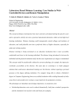
recognition. [5] One of the latest entertainment robots on the market is the Robovie. Robovie
is also a kit form robot that incorporates many high powered servos to give the robot a large
freedom of movement, Robovie is a humanoid based robot, which includes external giros and
an accelerometer which acts as a tilt sensor so that the robot knows when it has fallen over.
Robovie has a Hitachi H8/3687 20MHz microcontroller which can be programmed using the
bespoke software that comes with the kit. There are various applications for this robot which
use its large movement capability, one of them being the ―RoboCup‖ which is International
robot soccer this is shown below in figure 2-1. [6] The Robovie however has been customised
for all sorts of applications. The people at the ATR institute based in Osaka Japan have
customised Robovie to help lost shoppers in a shopping mall. [7] As described in the
introduction the primary function of the robot head to track human movement will be as a
Thomas Dunklin | A Robot Head to Track Human Movement
6
School of Electronic, Communication and Electrical Engineering
BEng Final Year Project Report
display piece for the entertainment of visitors and as a learning tool so many comparisons can
be drawn between these entertainment robots and the project described in this report.
Figure 2-1 Robovie Football Playing Robots [6]
The last robot to be analysed is a robot that has made a big impact on the robot world in
social interaction, the ASIMO robot designed and built by Honda. ASIMO is of full human
height, fully mobile bipedal humanoid robot that uses an array of sensors and actuators to
interact with the humans in its environment. ASIMO is described as a people friendly robot
which is designed to be human like and operate light switches, door knobs and be able to
work at work benches. The ASIMO is designed to work in the human living space. [8] ASIMO
is not only designed to do menial human tasks, it has a complicated artificial intelligence
system which enables it to interact with humans using the following functionality:
1. Recognition of moving objects
2. Posture/gesture recognition
3. Environment recognition
4. Sound recognition
5. Face recognition
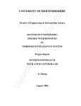
The ASIMO robot uses a camera mounted in its head to extract information about moving
objects so it can judge distance, follow a person or greet a person when they come near. This
is similar but a lot more advanced than the project described in this report. Using the visual
information ASIMO can interpret the positioning and movement of a hand, recognizing
postures and gestures. Thus ASIMO can react not only to voice commands, but also to the
natural movements of human beings as shown below in figure 2-2.
Figure 2-2 ASIMO view of how gesture recognition works [9]
Thomas Dunklin | A Robot Head to Track Human Movement
7
School of Electronic, Communication and Electrical Engineering
BEng Final Year Project Report
ASIMO can use the visual information for environmental recognition, which means it can
avoid static objects, as well as moving objects such as a person that comes into ASIMOs
path. ASIMO can use facial recognition software to recognise the faces of people when they
are static or when they are moving by having a database of pre- programmed people in its
memory. [9] The facial recognition concept could be adapted to be used for further study of
the robot head to track human movement.
2.2 Tracking Systems
There are many different ways of tracking moving objects such as humans, all of which have
strengths and weaknesses depending on their application. Some of the tracking systems that
are more relative are considered below in order to show how tracking works.
The first system is the use of sound waves to track objects. There are multiple ways of using
sound waves to track objects for example; Sonar is a system that uses transmitted and
reflected underwater sound waves to detect and locate submerged objects or measure their
distances underwater.[10] Sonar has been used since the 1912 on ships to sense
underwater dangers such as icebergs, submarines or mines.[10]
Another sound based tracking device uses ultrasonic sensors, the articles [11] and [12]
explain how ultrasonic sensors can be used to track an object when it moves through space
[12] shows that as well as being able to use the information from the sound wave that has
been sent back and process it to gain a picture of target object that is being tracked. The
advantages of using ultra sonic waves to construct pictures of objects over using a
conventional camera are that the lighting conditions of the environment will not affect the
sound waves so if the object is shiny there will be no loss of quality than if the object was
dark. The disadvantages are that if the object has a low density the sound wave will be
absorbed more giving a false reading of how far the object is away. [11]
Digital cameras use the visible spectrum of light to create images. Light is focussed onto a
silicon chip that contains a grid of boxes, each of which are sensitive to different colours of
light. After light passes through the lens, it stimulates these boxes, generating a different
voltage which is proportional to the amount of light. This voltage gets converted into a single
numerical value for each channel. [13] Digital cameras can use this digital map of values with
the aid of processing to track objects based on colours and size of objects. Colour tracking is
the ability to take an image, isolate a particular colour and extract information about the
location of a region of that image that contains just that colour. [14] One such system is the
CMUcam2+ this system uses red, green and blue (RGB) colour channels. The user inputs
minimum and maximum values of each channel colour, to allow a colour to be set and
tracked. The problem with this is that you need to specify a large range of colour for each
channel because the lighting conditions the colour of an object making it lighter or darker,
Thomas Dunklin | A Robot Head to Track Human Movement
8
School of Electronic, Communication and Electrical Engineering
BEng Final Year Project Report
changing the values of the channel specific to that object colour. So this process will work
very well for bold bright colours on a pale or dark background, but would not work very well on
different shades of blue or brown. [14]
2.3 Hardware
There are two main pieces of hardware used in this project other than a PC which is a
standard piece of equipment and does not need to be explained. These two pieces of
hardware are CMUcam2+ which is the camera mounted board and the Z8 microcontroller.
2.3.1 The CMUcam2+
The CMucam2+ is the later model of the second generation of CMU cameras. It is an
upgrade from the CMUcam2 which has many similarities and so share a user manual and
software interface. The major difference between the two is that the CMUcam2+ has the
camera integrated on the board instead of it being separate. There has now been a third
generation of the CMU camera released called the CMUcam3 the differences between the
CMUcam2+ and the CMUcam3 are that the CMUcam3 has all of the functionality of the
CMUcam2+ but with a better camera and an onboard open source programmable
microprocessor, where executable programs can be flashed onto the hardware via a serial
port without any external downloading devices. [27] This new generation is not used in the
project but is something to consider when proposing future work.
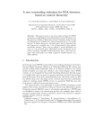
The CMUcam2+ consists of an SX52 microcontroller interfaced with an OV6620 Omnivision
CMOS camera. This board makes it possible to extract large amounts of data from the
streaming video output from the camera. Its primary use is to track and monitor colour in
particular highly contrasting colours. This ability and primary use is why the CMUcam2+ was
chosen to be the tracking sensor of the robot head. The CMUcam2+ communicates through a
TTL logic port which can be adapted for serial communication through an RS232 cable. [29]
The CMUcam2+ can be seen below in figure 2-3.
Figure 2-3 CMUcam2+ [29]
Thomas Dunklin | A Robot Head to Track Human Movement
9
School of Electronic, Communication and Electrical Engineering
BEng Final Year Project Report
The CMUcam2+ has many functions and features the most relevant of which are:
Track coloured blobs at up to 50 frames a second
Find the centroid of the tracking data
Dump a raw image
It supports multiple baud rates which is useful for communication with
microcontrollers
Can control up to 5 servo outputs for moving the head to track a colour
Can automatically use servos to do two axis colour tracking
It has flexible output packet customisation (used for external image processing)
Multiple pass image processing on a single buffered image
[28]
These features are all used in the design of the robot head. The CMUcam2+ can, using these
features find a colour that is user specified. Then identify the position of the centroid of that
colour, output the data about this image to a micro processor and then take commands in to
move the camera position.
Alternatively the CMUcam2+ is capable of tracking a colour automatically using the firmware
on the camera, whereby the tracking can be initialised by pressing the input buttons on the
camera. The support for the camera also comes with a graphical user interface or GUI, this is
a small piece of software that can show what the CMUcam2+ can do by sending it control
commands from a PC. This software will receive raw images and then you can select colours
from the image selected which will then send a tracking command to the horizontal and
vertical servos. This is a good tool for learning about the CMUcam2+ and how it works but
cannot be used for the sole implementation of the project as there is not a third servo control
which is needed to control the eyes of the robot head. As well as the GUI a terminal emulator
can interface with the camera and send a number of commands to control the camera, these
commands can be found in the appendices.
2.3.2 The Z8 Microcontroller
The microcontroller used in this project was a Z8F642 this is part of the Zilog eZ8 Encore! XP
series of processors. This particular processor is mounted on the Zilog Z8 encore
development kit, which is a kit designed to for developing programs to increase the
capabilities of the microcontroller. The Z8F642 has 64KB of programmable flash memory,
4KB of register Ram, twelve channel 10-bit ADC, two Full-duplex UART and an on chip
debugger to name some of the more relevant features of the MCU. The development Kit
contains 3 led‘s for debugging and to show how small programs can run. The kit also has an
Thomas Dunklin | A Robot Head to Track Human Movement
10
School of Electronic, Communication and Electrical Engineering
BEng Final Year Project Report
RS232 interface which will be used for communication with CMUcam2+, 2 push buttons one
for testing one for resetting the board, a crystal oscillator and a prototyping area which will not
be used in this project. [18] The Zilog Z8 encore development kit can be seen in the picture
below in figure 2-4.
Figure 2-4 Zilog Z8 encore development kit [18]
The Z8 development kit comes with its own compiling software called ZDSII. This is a
standard format of compiler interface with the usual debugging buttons such as step over,
step into, watch etc. This software is used for programming the Z8 MCU as well as compiling
and debugging the programs created, it uses standard C programming libraries as well as
some custom libraries just for the Z8 MCU. The PC to development kit communication is done
in one of two ways, via the serial smart cable or the USB smart cable depending how old the
kit is (the newer kits have USB smart cables). These smart cables are used for sending code
and debugging information to and from the PC and Z8 development Kit.
2.4 Previous work
The first project that is going to be described is a project titled ―a sound following robot head‖
written by Gilad Halperin carried out at the University of Hertfordshire. [20] This project has
the same basic tracking principals of the robot head to track human movement, in that its
aims were to turn towards people when the robot detects humans except this robot detects
sound. Although this project uses sound instead of colour to track comparisons can be made
between the two projects such as moving towards its target, that is to be tracked what can be
learnt from this project is that noise from the machine itself in servo motion contributed to
problems in tracking whereby the robot would move to hear itsself and form a feedback loop.
As the CMUcam2+ will not emit colours to confuse the system colour tracking seems a better
way of tracking human movement.
The second project also carried out at the University of Hertfordshire is titled ―A Mobile Bin to
Catch Rubbish‖ by Brijesh Kalani [21] This project uses the predecessor to the CMUcam2+,
Thomas Dunklin | A Robot Head to Track Human Movement
11
School of Electronic, Communication and Electrical Engineering
BEng Final Year Project Report
the CMUcam2. The CMUcam2 is used to track the selected colour of rubbish and then
respond appropriately to move towards and catch the rubbish. Although this project did not
reach completion, there are two things to be learnt from this project firstly that the CMUcam2
can be used to successfully track colour which could be adapted for use with the tracking of
humans. Secondly that in further work it is described that a Z8 processor could be used
control the CMUcam2 to further develop the capabilities of the bin. This is a good indication
that research has been done to satisfy the notion that a Z8 microcontroller can be used to
control the CMUcam2+. [21]
The last project to be described also comes from the University of Hertfordshire and is titled
―Controlling a Robot with Hand Signals by Image Segmentation‖ written by Apkesha Gandhi.
This system controls the movement of a robot using hand signals by tracking a specific
colour, yellow in this case and then by using an algorithm constructed in Matlab it tracks the
centre of gravity of the colour in different patterns when the hand is moved. The algorithm
then tells the robot to react to the different patterns. This project also uses colour tracking for
control of a robot just as the robot head project described in this report will. What can be
learnt from this project is that the use of image segmentation could be used for tracking a
human. [22]
Thomas Dunklin | A Robot Head to Track Human Movement
12
School of Electronic, Communication and Electrical Engineering
BEng Final Year Project Report
3. Description of Project Work
This chapter of the report will describe the practical work that has been carried out over the
allotted time period. This chapter will also show the work that was done and what decisions
were made to achieve the objectives set. The design decisions will be analysed and reasons
shown for each decision, the other options will be examined as to why they were not used.
The difficulties and problems encountered along the way in the project will also be discussed
and how these problems were overcome. Each of the following sections will be detailed
descriptions of the outcomes achieved and how it follows the objectives stated in the
introduction.
3.1 Familiarisation with the CMUcam2+
To start the project firstly the CMUcam2+ had to be obtained and become familiar with so that
proper operation of the CMUcam2+ was insured (although new functions and abilities of the
CMUcam2+ were found throughout the project duration). The CMUcam2+ was found and was
already assembled as previously stated a similar project had already been undertaken. The
CMUcam2+ had already been mounted on a specialised turret and fitted with servos for
horizontal (side to side) movement of the camera and turret which will now on be referred to
as the ―robot head‖ and vertical (up and down) movement of the robot head. A modification
that had been made to the original turret was the addition of an extra servo and a pair of
movable eyes. Once the overview of the robot head was familiarised it was time to power it up
and test if it was working properly. From the small Acroname booklet that had come with the
camera the power input pins were located and the correct voltage of 6 to 15 V was found.
Using a power supply, a middle range voltage of 12V was selected and applied to the power
inputs via a small length of wire. The CMUcam2+ was then switched on. Immediately after
power up, the whole robot head started to shake violently. From further research it was found
that the servos were taking power from the camera board via a jumper. This jumper was
removed and a 5V supply replaced it to power the servos. When the CMUcam2+ was
switched on again the head swivelled sideways into its start position and then was still, the
green power LED was illuminated. This was a positive sign that the CMUcam2+ was working.
The next stage was to connect the CMUcam2+ to a computer to communicate with the
CMUcam2+ and to see if everything was working, such as the Omnivision camera and the
microprocessor. The CMUcam2+ has a TTL serial port which can connect to the serial port on
a computer this is an RS232 interface. For this communication a level shifting circuit was
needed to change the voltages from the pc to the correct 0-5V range of the CMUcam2+. To
do this a Max 232 microchip was used in the configuration shown below in figure 3-1. In the
box with the CMUcam2+ an RS232 male connector had already been constructed with RX TX
and ground cables so this was checked and used to save time on building one the
Thomas Dunklin | A Robot Head to Track Human Movement
13
School of Electronic, Communication and Electrical Engineering
BEng Final Year Project Report
configuration can be seen below in figure 3-2. The level shifting circuit was constructed and
then connected to the CMUcam2+ TTL outputs and the computer serial port.
Figure 3-1 Typical Operating system of a Level shifting Circuit [23]
Figure 3-2 Pin connections for RS232 Link cable with wiring colours [24]
With this connection constructed the next logical step was to follow the instruction booklet and
run the GUI that was downloaded from the CMU website [25]. Although the instructions were
followed by installing the java GUI and running it, when the CMUcam2+ was turned on
nothing happened. The expected welcome message was not seen and various ideas were
tried to overcome this problem. The GUI was reinstalled, the COM port was changed and the
port settings were changed to make sure that the settings for the CMUcam2+ matched that of
the port. These settings are 115200Baud, 8 data bits, 1 stop bit, no parity bit and no flow
control. This still had no effect on the outcome, so the level shifting circuit was rebuilt with
new components in case any of them had become damaged. After almost a week of
troubleshooting David Lee was consulted and he suggested the use of a terminal emulator to
try and communicate with the CMUcam2+. The terminal emulator used was the free program
Thomas Dunklin | A Robot Head to Track Human Movement
14
School of Electronic, Communication and Electrical Engineering
BEng Final Year Project Report
called TeraTerm pro. This terminal was set up with the parameters listed above and then the
CMUcam2+ was turned on. The display read:
―:CMUcam2 v1.0 c6
:‖
This was good news as it meant that the camera was sending data to the terminal emulator
and communicating. After experimenting with the setting the local echo was turned on and an
add line feed was added to make things clearer. Then using the TeraTerm some commands
were sent to the CMUcam2+. The first was ―gv‖ which returned an ―:ACK‖ which is an
acknowledge signal and then the same version data as above was displayed. The second
command tried was a servo movement command ―sv 0 210‖ the CMUcam2+ returned an ack
signal and then the robot head spun to the left. This meant that the microcontroller was
working and controlling the servos. After proving that the CMUcam2+ was operational, the
GUI was tried once more. The GUI display panel showed the welcome message after turning
on the CMUcam2+, this was confusing as it would not do this when tested before. It followed
that the GUI would only work after the terminal emulator had been run. It is still not known
why this was but it seemed to have something to do with the COM port set up.
With the GUI up and running the testing of the camera could be started, firstly a frame was
grabbed which showed an image of the student in front of the camera. This image seemed to
be in focus and experimentation continued. The GUI has a servo control panel which showed
and controlled the movement of the servos these could be moved and all of the servos were
shown to work and the limitations were noted down so that they were not told to go further
than they could which may cause damage. These limitations were: horizontal (46-210),
vertical (51 to 210) and eyes (49 to 210). Each of the servo start positions when the camera
was turned on are 128.
The GUI also has an automatic tracking mode where you can select a colour for tracking from
the grabbed frame, then it selects the colour tolerances, and then tracks that colour. The
problem that was found with the auto tracking was that it was unreliable and would not follow
all the way around the robot head. This method is also unsuitable for the purpose of the
project because eye movement is required and auto tracking does not control any servos
except vertical and horizontal. Another observation was that it would sometimes invert the
movement so instead of moving towards the tracking colour it moved away.
Once the CMUcam2+ was found to be fully operational and an insight into how the tracking
worked had been made, it was time to implement control of the CMUcam2+ with a suitable
microcontroller. This is explained in the next section.
Thomas Dunklin | A Robot Head to Track Human Movement
15
School of Electronic, Communication and Electrical Engineering
BEng Final Year Project Report
3.2 Micro Processor Control
In choosing a microcontroller there were several options available. The previous experiment
carried out similar to this project used a PIC microcontroller, but that project was less than
successful due to various reasons one being the PIC was not sophisticated enough. So a
better processor was needed. Recommended were two microcontrollers one was the Z8
Encore! microcontroller and the other was a new Microsoft kit, research into the kit sounded
interesting but due to the low number of kits available if it was used then a time share would
have had been operated which could have been complicated. The Z8 microcontroller
described in the previous chapter was ideal for what was needed so this was the processor
chosen.
The first thing done with the Z8 development kit was powering up and connecting to a
computer, then using the latest version of the Zilog ZDSII software (version 4.10) a sample
program was downloaded from the computer to the MCU to familiarise with the whole system.
Not knowing the program or the microcontroller, it was unknown how long the downloading
process should take but after approximately 5 minutes it showed an error message and then
the program seemed to run. It was a small sample program found in the ZDSII software that
flashed the three LEDs sequentially until an input was fed in and then it changed direction.
Small adaptations to the sample code were made to change the sequence and then
downloaded again, but the sequence did not change which was unexpected. It was also
noticed that when the development kit was reset it sometimes only showed 1 LED or maybe 2
LEDs flashing. A colleague that was using the same kit was consulted and it was found that
his first board was faulty, so another board was obtained and this one worked better as the
new code was downloaded and the LED sequence changed. The Z8 development kit was
now operational but a lot of time had been wasted with a faulty board.
It was seen in the sample program that printf statements were used to output strings such as
―all leds off‖. On testing the Z8 the RS232 UART was connected to a terminal emulator on the
computer this came out with what seemed to be random characters. The baud rate of the
terminal emulator was changed to match the baud rate of the microcontroller, 57600 baud.
The display then read a sequence of ―red light on green light on yellow light on‖, this meant
that the printf statement could be used to send commands to the CMUcam2+ just as had
been done with the terminal emulator earlier in the project. This gave rise to the fact that all
that was needed to now control the CMUcam2+ was a female to female serial cross over
cable. The cable would need to be a cross over cable because the TX and RX I/O on both the
CMUcam2+ and the Z8 would need to complement each other for communication. A cable
like this was not available in the lab, so one was fabricated in the configuration shown below
in figure 3-3. With this cable the CMUcam2+ and the Z8 development kit were connected via
the RS232 ports on both devices.
Thomas Dunklin | A Robot Head to Track Human Movement
16
School of Electronic, Communication and Electrical Engineering
BEng Final Year Project Report
Figure 3-3 Cross over cable Connection Schematic
It was now time to start programming the Z8. The sample program was modified slightly to
incorporate a move servo command (this program will be described in a later section). Once
this program had been downloaded the Z8 debugging took place and a step over was used to
move the program along line by line. After the first debugging session and nothing happened
it was realised that the baud rate of the CMUcam2+ was set to 112500 whereas the baud rate
of the Z8 development kit was 57600. After researching the CMUcam2+ further it was found
that the CMUcam2+ could change baud rates via a pin jumper setting these jumper settings
are shown below in figure 3-4.
Figure 3-4 pin connections for CMUcam2+ baud rate selection [26]
With the CMUcam2+ baud rate set to match that of the Z8 the debugging and program
writing could continue. The debugging took approximately 6 sessions to get the correct
commands in the right place. On the first successful session the robot head turned to its
extreme right point which was the command that was sent. This was good news and
completed the move head in the horizontal plane objective. It was noticed however that
whenever a debugging session was ended, the program modified and a debugging session
restarted it took a very long time sometimes up to 20 minutes to download the program to the
Z8. This was an unacceptable amount of time being wasted. It was suspected that this like
the previous Z8 was faulty so another replacement was asked for. The third Z8
Thomas Dunklin | A Robot Head to Track Human Movement
17
School of Electronic, Communication and Electrical Engineering
BEng Final Year Project Report
microcontroller was connected and the servo move program was downloaded to it, although
the ZDSII software said it had downloaded the lights flashed in a wrong sequence much like
the first faulty Z8. Ian Monroe was consulted about the third faulty Z8 development kit and
other microprocessors were considered. It was suggested, that a brand new Z8 was used. So
the fourth Z8 Encore! XP was setup this was a newer version with a USB smart cable. The
Program was downloaded to the fresh Z8 and then it was run. It looked like the program was
working indicated by the LEDs flashing in the correct sequence and it would start and stop
debugging relatively quickly compared to the second faulty Z8. With these hardware issues
overcome, the programming could now begin and tracking could be achieved. These
hardware issues although relatively easy to fix took a long time to analyse and wasted a lot of
time that could have been used to develop the program codes further.
3.3 CMUcam2+ Testing Using a Terminal Emulator
Before writing the tracking program it was required that the tracking process was understood
and could be produced by sending line commands using a terminal emulator, so it could be
reproduced in a continuous loop in a microcontroller program. The CMUcam2+ was
connected via the serial port to the PC and then the terminal emulator TeraTerm pro was
started. Research was carried out into the various commands that the CMUcam2+ took. The
appropriate commands to get the desired outcome were selected and tested. The first
command tested was ―TC‖ this is the track colour command. The TC command uses
minimum and maximum values of red green and blue to track a colour between those limits.
The TC command once set sends a standard T packet. A T packet is a string of information
and looks like this example ―T 86 22 85 22 87 22 0 0‖. This corresponds to the following:
― T mx my x1 y1 x2 y2 pixels confidence‖ Where:
mx - The middle of mass x value
my - The middle of mass y value
x1 - The left most corner‘s x value
y1 - The left most corner‘s y value
x2 - The right most corner‘s x value
y2 -The right most corner‘s y value
pixels –Number of Pixels in the tracked region, scaled and capped at
255: (pixels+4)/8
confidence -The (# of pixels / area)*256 of the bounded rectangle and
capped at 255 [27]
The TC command was typed into the terminal emulator and what came back were continuous
sets of T packets with all zeros in it. This was because there were no tracking parameters set.
This was followed by the ―ST‖ command the ST command is use to set the tracking
parameters, so every time a TC is sent after an ST is set the TC will send a T packet
corresponding to those parameters.[28]
Thomas Dunklin | A Robot Head to Track Human Movement
18
School of Electronic, Communication and Electrical Engineering
BEng Final Year Project Report
An experiment was carried out with a red dot drawn on a piece of paper approximately 3cm in
diameter. This will from now on be referred to as the test dot. This was shown to the
CMUcam2+ in the GUI and the colour maximums and minimums were found. These tracking
parameters were then put into the terminal emulator using the ST command and then a TC
command was sent as well. As before a continuous set of T packets were output from the
camera, but this time different numbers populated the T packets. When the red test dot was
moved around in front of the camera the number changed. This meant that the CMUcam2+
was effectively tracking the test dot around the cameras FOV. The following information was
extracted from this experiment:
The horizontal field has from 0 to 90 pixel columns. 0 being the left side of the FOV.
The Vertical field has from 0 to 144 pixel rows. 0 being the Top of the FOV.
The optimal colour range for tracking red is ―ST 130 190 0 41 0 41‖
The next command tested was ―BM‖. The BM command is used to control the buffer mode of
the camera. Setting the buffer mode to 1 means that a single frame will remain in the buffer
this enables multiple processing calls to be made to the same frame. [29] Originally this
command was going to be used together with an RF command (which refreshes the frame in
the buffer) for the tracking however as the processing will be done in the external Z8
processor this command was not used. Another command was used, the ―PM‖ command.
The ―PM‖ command is used to control the pole mode. When the pole mode is asserted to 1
only a single packet is returned at the call of each TC this is useful because it will help with
real time tracking if the buffer is continually being updated and the TC will take a single packet
of information at any time and there is no problem with refreshing the buffer. [30]
The next command tested is one more to streamline the operation and is not necessary but
useful. The command ―OM‖ is used to mask the output of a packet only the information
wanted is received. So, if only the ‗mx‘ and ‗my‘ values are wanted, a command of ―OM 0 3‖
would give an output of ―T 40 128‖. This means that only the information that is wanted will be
taken in by the external microprocessor. [31]
The last command was tested at a later time but will be put in this section for continuity. It is
the ―DM‖ command, this command controls the delay set between the characters sent out of
the serial port this is particularly helpful for slower microprocessors. So a ―DM 255‖ sets a
maximum delay between characters sent. [32]
Thomas Dunklin | A Robot Head to Track Human Movement
19
School of Electronic, Communication and Electrical Engineering
BEng Final Year Project Report
3.4 Software code development
With all of the hardware connected and successfully tested and the CMUcam2+ tracking
system understood, the tracking code could be developed. This was done in small stages to
eliminate confusion and make debugging easier. All of the programming was done using the
ZDSII software. The first step was to create a code which could send a command to the
CMUcam2+ to see if communication was possible. The first command chosen was the SV
command which has a visual result of the robot head turning if the command is received. This
was done by altering the sample code shown in appendix i. The new code changes the printf
statements to a servo movement command ―sv 0 60‖ this adapted code is shown in appendix
ii. The Head turned and this was proof that the CMUcam2+ will accept commands from the
Z8 MCU.
The next priority was to make sure that the command was received when a visual recognition
is not available for example for camera initialisation commands like PM or TC. For this an
acknowledge program was written. This uses the function of the CMUcam2+ whereby an
ACK signal is returned after each command is received, accepted and executed. If a
command is received but not accepted, for example if only part of a command is received
then an NCK signal is returned. So a small piece of code was written and can be seen in
appendix iii. The whole acknowledge code is put into a do-while loop. Then using a printf
statement a command is sent, in this code it is a servo moving command. After the command
is sent a scanf reads in any characters input, into an array declared earlier in the program
called ―AS‖ standing for acknowledge string. Once this string has been obtained a strcmp was
used. This is a code that compares two strings and returns 0 if the two strings are the same.
The string compare compares what is stored in the array AS and a predefined char ―ack‖
which contains the characters ―ACK‖. The do-while is then ended with the condition that the
result from the strcmp is not equal to zero. So if the acknowledge is returned from the
CMUcam2+ then continue down the program if the acknowledge signal is not sent then resend the command. Just this section of the code is shown below for illustration.
do {
printf("sv 0 60\n");
scanf("%s", AS);
result = strcmp(ack, AS);
} while (result!= 0);
When this code was run it did not work so debugging was carried out. It was found that when
the program was stepped through, the program would stop, waiting for the scanf, this is
because there is too much time delay between the ACK signal being sent and the scanf being
initialised, so a breakpoint was inserted at the result line and step over was used. It was found
that as the program was stepped over, although after the printf command was executed the
robot head moved, the result of the strcmp was not 0 even though it is certain that an ACK
Thomas Dunklin | A Robot Head to Track Human Movement
20
School of Electronic, Communication and Electrical Engineering
BEng Final Year Project Report
was sent. The next stage was to look at what was being read into the array AS, this was done
using the watch panel in the ZDSII software. The watch panel was set up with the array AS
and the integer variable result. When the program was stepped over, a colon was seen in the
first element of the array every time the loop continued this happened. This was due to the
fact that the CMUcam2+ sent a colon after every signal to indicate that it is ready for new
input. This was simply remedied as it was known that there would be a colon in front of every
received signal. The defined char ―ack‖ was modified to become ―:ACK‖. Another problem
was that when the program was run without breakpoints the array AS showed that not an
―:ACK‖ was given out but an ―:CK‖ this was unexpected and could result in major breakdown
of the program as the difference between the acknowledged ACK and not acknowledged
NCK is the single character that is being omitted. It was unknown why this character was not
being read but was suspected to be a buffering problem. After much analysing a test was
carried out to see if the characters were being sent faster than the Z8 could read. The
CMUcam2+ was set up using the terminal emulator and the delay mode DM was set to its
highest of 255. The CMUcam2+ was then reconnected to the Z8 and the program was set to
run once again. But this time the full ―:ACK‖ was observed in AS and the program carried on
to the next line. This was then tested with a command that was known to return a ―:NCK‖ and
it did so making the program loop infinitely as it would never get an acknowledge from this
incorrect command.
Once this acknowledge function was working it was used to write a code to initialise the
CMUcam2+ for tracking. This sets the camera up using the following commands, this code
can be seen in appendix iv. Firstly the delay mode is set for being able to read characters in
properly, and then the pole mode is set to 1 followed by setting the tracking parameters to
track red in this example. Then finally the output masking was implemented. This set of
instructions will be known as the camera initialisation from now on as they are standard in the
following versions. This version in appendix iv also shows a first attempt at taking information
in using the TC command. The program after initialisation shows an infinite while loop which
contains a call to TC then if the acknowledge signal is accepted, a scanf function is used to
read in the T packet and store each element in their respective variables. This method did not
work however because some portion of the input would not work and the program would hang
on this line.
The second version of this program shown in appendix v uses a gets function to store the T
packet after it is sent. The gets function takes characters and stores them in an array ―AS3‖.
This method of reading information in worked fine and the program carried on to the next line.
The next part of the program turns the character data in the array into useful information that
can be used for tracking. Firstly element four of the array AS3 is compared with the number
32 this is because the numerical value of a space character is 32. The reason for checking if
this element is a space is to determine if a one or two digit number has been sent for the
Thomas Dunklin | A Robot Head to Track Human Movement
21
School of Electronic, Communication and Electrical Engineering
BEng Final Year Project Report
value of ‗mx‘ so if there is a space in this element then ‗mx‘ is a two digit number and if there
is not then the value of ‗mx‘ is a single digit number. The comparison is done in an IF
statement which then carries an equation out if ‗mx‘ is two digit. This equation is:
mx=((AS3[3]-48))+((AS3[2]-48)*10);
The reason for taking 48 from each element in the equation is that the numbers stored in
these elements are character versions and have a different numerical value to their integer
counter parts. To convert from character number to integer all that is needed is to take away
48. The reason for multiplying the first digit by 10 is because this is a two digit and that is the
tens number. So the output of the equation should be the integer value of ‗mx‘ sent by the
CMUcam2+. After this equation is done to change the character into an integer an If function
is used that says if the x coordinate of the tracked object is bigger than 48 to turn left and
another IF function is used to say if the x coordinate is smaller than 48 to turn right. This code
was tested and was the first program that could do limited horizontal tracking by turning to the
right or the left with the red test dot.
The next step was to make the eyes move. Due to the research done and the brief being that
the robot should act in a human like fashion, it was found that humans do not sweep their
eyes to meet a target their eyes jump what they want to see, i.e. the saccade effect. So
instead of moving the eyes left until the target was in range, it was decided that the eyes
would jump to a corresponding point to where the target is. The next piece of code, shown in
appendix vi moves the eyes to track a target. It follows the same basic format as the previous
code by initialising the camera and then obtaining the integer value of ‗mx‘, after ‗mx‘ is
obtained another equation is used to calculate the corresponding servo position. This
equation is shown below:
svpos=((mx*2)+50);
This equation was calculated by the fact that the camera has a horizontal range of 0 to 90 and
the eye servos have a range of 50 to 210. To map the camera position to the servo position
50 was taken from 210 which is equal to 160 and then 160 was divided by 90 which is 1.8.
This number was rounded up to two as the servo position must be a whole number. The
equation then adds 50 to get in the servo range. Once the servo position is calculated, If
statements are used, the If statement compares the servo position to 50, if the servo position
is 50 it means that ‗mx‘ was zero and so there was no red found in the cameras FOV. If this is
the case then the eyes revert into their start position of 128. If this is not the case a servo
move code is sent with the value of ―svpos‖ as the position for the servo to turn to. The final
part of the program is nested for loop which just creates a small delay so that the servos have
time to move before the next move command is sent. When this program was debugged it
was found that the program would run fine on the first loop of the program, but on any
subsequent loop it would stop on the first ACK validation after the TC is sent. After a lot of
Thomas Dunklin | A Robot Head to Track Human Movement
22
School of Electronic, Communication and Electrical Engineering
BEng Final Year Project Report
debugging using the watch command, it was found that for an unknown reason a second
colon was being received and therefore making the acknowledge string ―::ACK‖ which would
obviously stop the program and continuously send TC commands. This problem was
incurable in the time that was left. So as can be seen the do-while loop is commented out for
each of the commands in the loop. Even though the acknowledge string is not used, in testing
the program the outcome was as desired and the eyes flicked to the target and then to the
centre when there was no target in sight. This means that the command has been sent and
received on each loop.
Now that the eyes were tracking a target and moving in a human like way, the next thing to do
was to make the head turn when the eyes were at either extreme left or extreme right to get a
‗better look‘ at its target. This implementation can be seen in appendix vii. This piece of code
is the same as appendix vi but with more built onto the end within the while loop. This extra
code uses two stacked If statements to determine whether the servo position sv is in the first
or last 10 of the servo range. The first If statement finds if ―svpos‖ is larger than 1 the second
If statement finds if ―svpos‖ is smaller than 10. If ―svpos‖ is within these limits, ―var1‖ is
decreased by 20 then another If statement is used to stop the value ―var1‖ going too low and
breaking the servos. So if ―var1‖does go lower than 50 it is capped at 50. The next command
executes a servo move to the horizontal pan servo which uses ―var1‖ as the servo position.
This process is repeated for the other end of the scale from 80 to 90. Delays are used once
again to give the servos time to move. The result of this program is the final outcome of this
project whereby the robot can track the colour red left and right in the horizontal plane in a
human like way.
Due to time restraints vertical tracking and tracking using skin tones were two objectives that
could not be completed but the foundation of tracking using the Z8 processor has been
completed, so there is an option for future work to be carried out on this project to get to the
required stage where proper human movement could be tracked.
Thomas Dunklin | A Robot Head to Track Human Movement
23
School of Electronic, Communication and Electrical Engineering
BEng Final Year Project Report
4. Results and Discussion
It has been shown in the report that there are not any graphical or numerical results that can
be analysed to decide whether the project has been a success or not, instead the
achievements of the project and what have been learnt about tracking human movement by
this method are the results of this project. In this section these results will be identified and
discussed, to show the importance of the result, what has been learnt and what can be taken
away from this project.
The first major achievement was the ability to communicate with the CMUcam2+ through the
computer. This involved a lot of time and research to connect the CMUcam2+ to the computer
because a level shifting circuit had to be identified and built using a MAX232 microchip. This
was an achievement in itself because even though the circuit was provided for already in the
data sheet, it still needed to be researched, built and then tested. It is now known for future
reference that using this circuit the CMUcam2+ and a computer can communicate. Without
this link in communication, the project could not be finished to the stage that it has been.
The next achievement was being able to control the CMUcam2+ through a terminal emulator,
this entailed identifying the emulator and then setting it up to the required baud rate and bit
values of the CMUcam2+ which also needed to be researched for proper communication.
Once the link was established this enabled testing to be done on the CMUcam2+ to identify
the commands that would be useful when it came to programming the Z8 micro controller. In
testing the CMUcam2+ it was found that the ―SV‖ command could be used to change the
servo position and hence enable movement of the robot head. The ―TC‖ command was used
to track a single colour and with the output of this function get values of x and y coordinates
which could then be processed and used to determine the position of the servos. The ―OM‖
command was found to mask the output data of ―TC‖ for ease of processing. Both of the ―PM‖
and ―BM‖ commands could be used to give only one T packet data set out but it was decided
because less commands were needed for ―PM‖ and that processing power was not needed
on the CMUcam2+ side of the system that the buffer mode would be set to constant and the
poll mode (―PM‖ function) would be used.
The next stage of achievement was testing the CMUcam2+ field of view and servo output
maximums and minimums. The field of view of the CMUcam2+ was tested using the track
colour command. Using the red test dot it was found that the FOV of the camera was split into
0 to 90 columns and 0 to 144 rows. This experiment was important as the data gathered was
used to create equations for accurate tracking, and can be used for further work on vertical
tracking. The servo maximum and minimum positions were found using the CMUcam2+
GUI. These positions were: horizontal (46-210), vertical (51 to 210) and eyes (49 to 210). This
information is useful so that a command was not sent to go past these values, which may
have damaged the servos. This information was also used in the construction of tracking
Thomas Dunklin | A Robot Head to Track Human Movement
24
School of Electronic, Communication and Electrical Engineering
BEng Final Year Project Report
algorithm equations. Whilst testing the tracking it was found that contrasting colours were
tracked more easily such as red on a blue back ground. This information was important as it
influenced the decision of the target colour used later in the project.
The major achievement of this project would be the control of the CMUcam2+ using the Z8
microcontroller. This involved selection of the microcontroller and then using the ZDSII
software until familiar enough to program the Z8. The next part involved the physical
connection of the Z8 processor to the CMUcam2+; this was done after testing of the ZDSII
software showed that printf statements could be used to output ASCII characters to the
RS232 port on the development board. The connection was made using a female to female
cross over cable that was fabricated to meet the needs of the project. This fabrication was an
achievement because it needed research into which of the pin outputs needed to be
connected together, this also saved time that would have been wasted waiting for a
manufactured cable to be ordered and delivered. In testing the connection it was found that a
delay needed to be set between sending each character from the CMUcam2+. This
information was integral for communication because without it data could not be properly read
in by the Z8.
Once communication had been established between the CMUcam2+ and the Z8
microcontroller it was time to start programming so that tracking could be carried out.
Successful C programming code was achieved as it enabled the tracking to be done using the
Z8 processor which broadens the functionality of the project for current and future use. The
first element of the program enabled the handshaking of the two devices by using the
acknowledge string sent by the CMUcam2+this was a useful tool because it ensured the
correct command had been sent and received correctly. The next element of code
established the movement of the servos which enables the robot to turn and look at the object
being tracked. This is an important part of the project because without it there would be no
visual evidence of tracking.
The tracking of a specific colour using the eyes on the robot head is another large
achievement. This tracking uses the information obtained in previous tests of FOV size and
servo limitations. The tracking was produced whereby the eyes moved to a specific point
determined by the position of the tracked colour in the cameras FOV. The result is that the
robot head appears as though it is ‗looking‘ with its eyes at the target colour. This meant that
robot head tracking had been achieved using the Z8 microcontroller and that the robot head
could track in a humanlike way in its eye movements i.e. the saccade effect. The equation
used for eye tracking and movement was:
Servo position= ((2*x coordinate)+50)
The 2 should have actually been 1.8 to give an accurate servo position which corresponded
to the x coordinate but 1.8 was not used due to the fact that it produced non whole integer
Thomas Dunklin | A Robot Head to Track Human Movement
25
School of Electronic, Communication and Electrical Engineering
BEng Final Year Project Report
numbers which would not have been accepted by the CMUcam2+ as correct input. This
slightly reduced the accuracy of tracking using the eyes but was not a major issue because
the eyes still were pointing in the correct direction which was an unnoticeable difference to the
absolute position by the human eye. As this is designed to be a display piece humans will be
the judges of successful tracking and it was deemed acceptable that this discrepancy was in
the program.
The last piece of program enabled the robot head to turn when the target was on either side
of the cameras field of view. This achieved a more human form of tracking as the robot head
turned to ‗get a better look‘ at its target, therefore keeping it in view.
Although the final program worked in that it functioned and the outcome was as desired, it
was not as elegant as it could have been and still had some minor issues. These issues
include the repetitive initialisation commands being sent which could have been put in to a
function and called. The delays being initiated are large and space consuming these could
also have been put into a separate function. There was still an issue with the fact that the
acknowledge string is not used in the tracking loop because of the mysterious extra colon.
These problems could be fixed to make the program run smoother.
The final result of the project is a robot head which can track the colour red with its eyes first
in its field of view and then turn its head to the left or right to better track its target. This
tracking is achieved by using the Z8 microcontroller and associated programs. The tracking of
human movement was achieved to an extent. The tracking of human skin tones unfortunately
was not achieved because of time restraints but human movement tracking was achieved by
adapting the human target for the robot to track. This adaptation was done by putting red on
the human target somewhere, by either putting red clothes or by holding a red object. This
was tested by a person wearing a red jumper, when the person moved from left to right the
eyes moved to follow and then the head turned to keep the human in view, for this reason it
can be said that tracking of human movement was achieved.
It was unfortunate that due to time constraints the vertical tracking and tracking using skin
tones was not achieved. Vertical tracking would not be difficult because the ground work has
been done using horizontal tracking and the final program would only need to be adapted.
Tracking using skin colour would be more difficult however because it is hard to identify skin
colour using only red green and blue so the raw data of a tracked image would have to be
taken in and analysed, this would need the program rewriting.
Thomas Dunklin | A Robot Head to Track Human Movement
26
School of Electronic, Communication and Electrical Engineering
BEng Final Year Project Report
5. Conclusions
In conclusion the aim was to design and build a robot head capable of tracking human
movement. The application for such a project would be an interactive display piece which
would follow people when they were in range of the human head. This task was accomplished
using the CMUcam2+, a device with a CMOS camera mounted onto a microprocessor board,
which used the images from the camera for colour tracking. A secondary control was
implemented on the CMUcam2+ by the use of a Z8 encore! XP microcontroller. There were
three main objectives in this project, understanding the CMUcam2+, implementing a micro
controller which would set the tracking parameters of the target i.e. humans and writing a
program for the Z8 microcontroller that would track the target and then to track human
movement in a human like way.
This report has shown that a previous project was used which already had a robot head built
with the CMUcam2+ already mounted upon it, this robot head had the capability of moving in
both the horizontal and vertical planes as well as prosthetic eyes that moved left and right.
This report has described that the CMUcam2+ already has an automatic tracking system but
this was inadequate for this project because it could not move the eyes of the robot. This
previous project was modified for the objectives set in the robot head to track human
movement project.
The robot head was tested and controlled using a computer via a level shifting circuit. This
circuit was constructed and it interfaced the TTL logic port on the CMUcam2+ and the serial
port on the computer. Testing was carried out using a GUI that is made for the CMUcam2+
and a terminal emulator called TeraTerm pro. Various tests were carried out which involved
control of the servos that moved the robot head as well as various camera commands that
controlled the camera such as tracking commands and camera output commands, using this
method of testing, tracking of a red test dot was achieved whereby the coordinates of the
target were displayed on the terminal emulator when the target was moved in front of the
camera. Tracking is done on the CMUcam2+ by setting the red green and blue tracking
parameters of the target colour. This tracking achieves the first objective set. It was found
during testing that the best results of tracking happened when bright contrasting colours were
used such as a red target on a blue background.
Because of the inadequacies of the automatic tracking on the CMUcam2+ board, objective
two was to implement a Z8 microcontroller to control the CMUcam2+. This report has shown
that there were difficulties in this implementation, mainly by hardware failure which led to
delays. In the course of the project four Z8 Encore! XP development kits were used after each
of them failed, this failure may have been due to static interference or could have been due to
faulty boards, but the latter seems unlikely due to the fact that four different boards were
used. These failures have led to a lack of confidence in the Z8 development kit and it would
Thomas Dunklin | A Robot Head to Track Human Movement
27
School of Electronic, Communication and Electrical Engineering
BEng Final Year Project Report
not be recommended for any future projects, unless it is a brand new kit. However when the
hardware issues were overcome the Z8 microcontroller was interfaced with the CMUcam2+
by a female to female cross over cable which connected the RS232 ports on either device.
This cable had to be constructed due to resource limitations. Once communication was
established between the two devices, program code to control the CMUcam2+ was written.
The third objective was to communicate between the two devices. For successful
communication printf statements were used to send commands to the CMUcam2+. There
were some issues however with reading back from the CMUcam2+ to the Z8. The characters
read in would sometimes be missing or incorrect. This was remedied by initiating a delay
between the sending of each ASCI character from the CMUcam2+. A handshaking system
between the two systems was established, which made use of the acknowledge function of
the CMucam2+. This sent an ―ACK‖ when a command was received and understood. With
communication established the control of the CMUcam2+ was implemented.
The fourth objective was to track an object in the horizontal plane. There were three stages in
completing the tracking control of the CMUcam2+ with the Z8 microcontroller. These stages
were firstly getting the Z8 to send a move command which moved the head and eyes which
was completed successfully. The second stage was to initialise tracking by setting up the
CMUcam2+ for use with the Z8 then to send a tracking command and take the target position
data from the CMUcam2+ and store it to be processed later. This data read-in system was
accomplished by the use of the gets function which put the data in an array. The last stage
was to get the robot to react to the tracking data that was received. This was achieved by
taking the tracking data coordinates and processing them, by way of an equation and with this
equation sending servo movement commands to the servos that control the eyes and the
horizontal head movement.
The final result of the project is a robot which can track the colour red and display this tracking
by moving the eyes of the robot to the approximate position of the target. The final objective,
objective six stated that the robot must track in a human like way. Human like tracking was
achieved by the fact that the eyes jump position when a target comes into view. Then when
the target moves to the extremes of the cameras field of view the head moves to keep the
target in ‗sight‘. This human like tracking was achieved by an equation that relates the x
coordinate of the tracked object and the servo position. With a delay set between movements
the robot looks as if the eyes are jumping from place to place. These methods fulfil the
objective of human like movement tracking. The fifth objective was to track human movement
by use of skin tones. The final result of the project enabled tracking of a red object. If a human
were to wear a red piece of clothing or carry a red object the movement would be picked up
and tracked by the robot head, although this human tracking is not achieved by identifying
skin tones the robot head can do human tracking, so objective 5 is partially completed.
Thomas Dunklin | A Robot Head to Track Human Movement
28
School of Electronic, Communication and Electrical Engineering
BEng Final Year Project Report
The aim of this project was to ―design and build a robot head that will use the CMUcam2+
camera to identify an object ideally a human, and track its movements in a human like way by
use of a micro controller‖. This aim has been achieved as the CMUcam2+ and the Z8
microcontroller was used which can track a human (if they are wearing red) and by use of the
saccade effect produced by the eye movements human like tracking was produced. The
project therefore can be deemed a success because the aim of the project stated in the
introduction was achieved and the objectives that were set were completed.
5.1 Recommendations
The project can be seen as a success but due to time constraints there were some stages of
work that were not completed and some stages of work that were completed but could have
used more time spent on them to bring them up to a more satisfactory level.
Whilst writing the code for initialising tracking and reading data in, a problem was found which
could not be overcome in the time that was left. The problem was to do with the acknowledge
function that was written. This function made sure that the command sent was received and
was correct. The problem was that after the first loop of the program an extra colon was seen
before the acknowledge string. This was not the correct acknowledge string and so the
program stopped and looped infinitely. This problem was bypassed by not using the
acknowledge function and just sending the command and it was then taken on faith that the
command was received. It would be recommended that if this project was continued this
problem was fixed to ensure smooth running of the program. It is suggested that a piece of
code to mask this extra colon is used, or to find out why this colon is being sent in the first
place.
The finished code was although functional less than elegant and a lot larger than it should
have been. In real life engineering programming codes need to be as small as possible to
save on memory and therefore save on cost. Because of time restraints the code was not as
polished as it could have been. It would be recommended that this code was tidied up in the
following ways. A send command function could be created that could be called with various
set commands. This would eliminate a large amount of lines which are very repetitive in the
program. Delays are used throughout the project using for loops, this also takes up a large
amount of space a delay function could be built which could be implemented. The final code
also has a few redundant variables as well as some badly labelled variables. To complete this
project up to a higher standard these variables would be eliminated and renamed
respectively.
Thomas Dunklin | A Robot Head to Track Human Movement
29
School of Electronic, Communication and Electrical Engineering
BEng Final Year Project Report
Due to time constraints not all of the stages of work were completed the main two being that
vertical tracking was not achieved and that tracking using skin tones was not achieved. The
vertical tracking would be quite simple to implement using the code that has already been
written, although a small hardware modification would be needed as the eye moving rods
would get trapped by the vertical actuating rods on the robot head. The tracking using skin
tones would take some further analysis because it was found that skin tone tracking is difficult
using only the red green and blue tracking parameters. So it would be recommended that
more research be done into skin tone tracking to find out how this could be implemented on
the robot head. If skin tone tracking could be achieved this project could be seen as a true
success.
The equation for tracking uses a rounded up number 2 from 1.8 to relate the x coordinate of
the target to the servo position this rounding in effect causes a minor discrepancy to the
position of the servo and the position of the target. It would be recommended that this
equation be changed to use 1.8 and then a rounding algorithm on the result be used to create
a whole number. This would improve accuracy of tracking.
The final recommendation is regarding performance of the end result of the project. Human
like tracking of a human was achieved, the eyes moved to the target and then the head
moved to keep the target in view. Although the eye movement is a good reflection of human
behaviour, the head movement was jumpy and did not reflect human behaviour as well as it
could have. This movement could be made smoother by making smaller steps at smaller
intervals by reducing the size of the step movements and reducing the delays.
5.2 Further work
As with all projects there are many avenues a project could take as more research could be
done and more work could be carried out to make the project better and more complex to
more fully achieve the aims and objectives. The following are some suggestions that could be
carried out to further the project.
At present the Robot head uses a CMUcam2+ and a Z8 microcontroller. That needs an
interface and a lot of setting up and communication between devices. The newest generation
of CMU camera‘s is the CMUcam3 which incorporates a fully flash programmable
microprocessor which would eliminate the need for the need for the Z8 and handshaking
signals. So for further generations of the robot head a CMUcam3 would be recommended.
The benefits of this would be that more time could be spent on analysis of colour data and
tracking and less time spent on the interface.
Thomas Dunklin | A Robot Head to Track Human Movement
30
School of Electronic, Communication and Electrical Engineering
BEng Final Year Project Report
Another way to further the project would be to increase the functionality of the head by adding
new features. A suggested function would to firstly get vertical tracking of the head working,
and then modify the eyes and program to include vertical tracking of the eyes so that they
could move up and down as well as side to side which would make the tracking even more
human like. Another function could be to incorporate more human reaction in to the face like
the Kismet robot.
To increase the success of human tracking, more sensors could be added to the robot head
to detect other forms of human movement. The turret comes with mounts for ultrasonic
sensors that use a sonar-like system to detect objects. These sensors could be used in
conjunction with the camera for tracking.
The robot head could be made to look more like a human this could be done with a prosthetic
face which could overlay the mechanical parts. This would increase the realism of the project
and make interaction with the robot easier.
The imaging hardware and software could be improved to a stage that facial recognition could
be incorporated into the robot head, where it would track a human as it walked past and then
log the data somewhere for the next time the person walked past, this functionality could be
used to track the movements of particular people in an area or could still be used for
entertainment value if a greeting message system was installed and, it could tell you how
many times you have been past it that day.
This section has shown that more work could be done to the project. Every new idea that is
suggested is another way to improve the robot to the point where it is realistic enough and
tracks well enough to be a replica for the human head tracking system.
Thomas Dunklin | A Robot Head to Track Human Movement
31
School of Electronic, Communication and Electrical Engineering
BEng Final Year Project Report
REFERENCES
1. Lee, D, ―Introduction to Robotics and the Khepera Robot‖, Lecture notes February
2008, pp. 3-8
2. ―Kismet‖, http://www.ai.mit.edu/projects/humanoid-robotics-group/kismet/kismet.html,
16th February 2008
3. ―Mindstorms‖, http://mindstorms.lego.com/Overview/, 5th October 2007
4. ―Mindstorms NXT Software‖,
http://mindstorms.lego.com/Overview/NXT_Software.aspx , 5th October 2007
5. ―Aibo History‖, http://support.sonyth
europe.com/aibo/1_1_3_aibo_story.asp?language=en, 24 November 2007
6. “Robovie-M V3 Humanoid Robot Kit "Big-Max"”,
http://www.roboporium.com/roboviem_v2.html, 26th March 2008
7. ―Robovie Droid helps Lost Shoppers‖, http://www.pinktentacle.com/2008/01/roboviedroid-helps-lost-shoppers/, 26th March 2008
8. ―Design Concept‖, http://world.honda.com/ASIMO/technology/concept.html, 12th
March 2008
9. ―Intelligence‖,http://world.honda.com/ASIMO/technology/intelligence.html, 12th March
2008
10. ―The History of Sonar‖,
h
http://inventors.about.com/od/sstartinventions/a/sonar_history.htm, 5t October 2007
11. Kuang, W.T.; Morris, A.S.; ―Combined time-of-flight and Doppler ultrasonic tracking
system for better performance in robot tracking‖, Science, Measurement and
Technology, IEE Proceedings Volume 147, Issue 5, Sep 2000 Page(s):213 - 218
12. Watanabe, S.; Yoneyama, M.;An ultrasonic robot eye system for three-dimensional
object recognition using neural network‖ 1989. Proceedings, IEEE 1989 Ultrasonic‘s
Symposium , 3-6 Oct. 1989 Page(s): 1083-1086 Vol.2
13. ―CMUcam2 Vision Sensor User Guide‖ Edited by Charles Rosenberg and Illah
Nourbakhsh Copyright 2003 pp.6
14. ―CMUcam2 Vision Sensor User Guide‖ Edited by Charles Rosenberg and Illah
Nourbakhsh Copyright 2003 pp.P7
15. ―CMUcam3: Open Source Programmable Embedded Color Vision Platform‖,
th
http://www.cmucam.org/, 26 March 2008
th
16. ―The CMUcam2‖, http://www.cs.cmu.edu/~cmucam2/, 6 October 2007
17. ―Acroname Robotics‖, http://www.acroname.com/robotics/parts/R245-CMUCAM2PLUS.html, 6th October 2007
18. ―Z8 Encore! XP 64K Series Flash Microcontrollers Development Kit User‖, Copyright
©2007 by Zilog®, Inc., pp.9
19. ―ZiLOG Developer Studio II—Z8 Encore!® User Manual‖, Zilog®, Inc., July 2006
Thomas Dunklin | A Robot Head to Track Human Movement
32
School of Electronic, Communication and Electrical Engineering
BEng Final Year Project Report
20. Halperin, G, ―a sound following robot head‖, April 2005, pp.ii
21. Kalani, B, ―A Mobile Bin to Catch Rubbish‖ September 2005, pp.iii
22. Gandhi, A, ―Controlling a Robot with Hand Signals by Image Segmentation‖, August
2004, pp.4
23. ―Maxim +5V-Powered Multichannel RS-232 Drivers/Receivers‖,
http://datasheets.maxim-ic.com/en/ds/MAX220-MAX249.pdf, pp.17, 14th October
2007
24. ―CMUcam2 Vision Sensor User Guide‖ Edited by Charles Rosenberg and Illah
Nourbakhsh Copyright 2003 pp.30
th
25. ―The CMUcam2‖, http://www.cs.cmu.edu/~cmucam2/downloads.html, 6 October
2007
26. ―CMUcam2 Vision Sensor User Guide‖ Edited by Charles Rosenberg and Illah
Nourbakhsh Copyright 2003 pp.21
27. ―CMUcam2 Vision Sensor User Guide‖ Edited by Charles Rosenberg and Illah
Nourbakhsh Copyright 2003 pp.57
28. ―CMUcam2 Vision Sensor User Guide‖ Edited by Charles Rosenberg and Illah
Nourbakhsh Copyright 2003 pp.52
29. ―CMUcam2 Vision Sensor User Guide‖ Edited by Charles Rosenberg and Illah
Nourbakhsh Copyright 2003 pp.30
30. ―CMUcam2 Vision Sensor User Guide‖ Edited by Charles Rosenberg and Illah
Nourbakhsh Copyright 2003 pp.46
31. ―CMUcam2 Vision Sensor User Guide‖ Edited by Charles Rosenberg and Illah
Nourbakhsh Copyright 2003 pp.45
32. ―CMUcam2 Vision Sensor User Guide‖ Edited by Charles Rosenberg and Illah
Nourbakhsh Copyright 2003 pp.33
Thomas Dunklin | A Robot Head to Track Human Movement
33
School of Electronic, Communication and Electrical Engineering
BEng Final Year Project Report
BIBLIOGRAPHY
1. ―Human Robot Interaction‖, http://decsai.ugr.es/~salinas/humanrobot.htm
2. ―Human movement tracking technology‖,
http://www.xspasm.com/x/sfu/vmi/HMTT.pub.html
3. ―Z8F6423FT020SC Product Details‖,
http://www.zilog.com/productserver/datasheet.asp?FAM=8bit&PN=Z8F6423FT020SC
4. D. M. Gavrila, ―The Visual Analysis of Human Movement: A Survey‖ Computer Vision
and Image Understanding Vol. 73, No. 1, January 1999, pp. 82–98
5. B, Haigang; H, Qiang; Z, Weimin; S, Bo; L, Kejie; ―Visual Tracking of a Moving Object
of a Robot Head with 3 DOF‖, Proceedings of the 2003 IEEE International
Conference on Rohotics,lntelligent Systems and Signal Processing Changsha, China,
October 2003
6. G, Metta; A, Gasteratos; G, Sandini; ―Learning to track colored objects with log-polar
vision‖ Mechatronics 2004 pp. 989–1006
7. O, D´eniz; M, Castrill´on; J, Lorenzo; C, Guerra; D, Hern´andez; M, Hern´andez;
―CASIMIRO: A Robot Head for Human-Computer Interaction‖, 2002
8. L, Manfredi; E, Stefano Maini; P, Dario; C, Laschi; B, Girard; N, Tabareau; A,
Berthoz; ―Implementation of a neurophysiological model of saccadic eye movements
on an anthropomorphic robotic head‖, 2004
Thomas Dunklin | A Robot Head to Track Human Movement
34
School of Electronic, Communication and Electrical Engineering
BEng Final Year Project Report
APPENDICES
Appendix i Sample ZDSII code
////////////////////////////////////////////////////////
// Main program beings here
// This program blinks LED-3 on the evaluation board
void main ()
{
int ledstate = 1;
init_led_gpio();
init_test_button_gpio();
// Initializes LED ports (Port A)
// Initialize Test Button (Port C)
DI();
// Disable Interrupts
init_timer0();
init_uart0();
// Intialize Timer-0
// Intialize Uart
init_test_button();
// Initialize Test Button
EI();
// Enable Interrupts
while(1)
// Infinte while loop
{
if(ProgStat != BUSY)
// Wait for Timer Interrupt
{
if(button_push >= 2)
// Change direction if Button pushed
{
button_push = 0;
if(ProgDir == UP)
ProgDir = DOWN;
else
ProgDir = UP;
}
switch(ledstate)
{
case 1:
turn_off_led();
// Turns off ALL LED's
printf("Led Lights Off\n"); // Write to uart0
break;
case 2:
turn_off_led();
// Turns off ALL LED's
PAOUT &= 0xFE;
// Turn On LED Red
printf("Led Lights Red\n"); // Write to uart0
break;
case 3:
turn_off_led();
// Turns off ALL LED's
PAOUT &= 0xFD;
// Turn On LED Yellow
printf("Led Lights Yellow\n"); // Write to uart0
break;
case 4:
turn_off_led();
// Turns off ALL LED's
PAOUT &= 0xFB;
// Turn On LED Green
printf("Led Lights Green\n"); // Write to uart0
break;
}
ProgStat = BUSY;
// Change to wait state
ProgDir &= 0x01;
if(ProgDir == UP)
Thomas Dunklin | A Robot Head to Track Human Movement
35
School of Electronic, Communication and Electrical Engineering
BEng Final Year Project Report
{
ledstate++;
// Shift Led
if(ledstate == 5 )
ledstate = 1;
}
else
{
ledstate--;
// Shift Led
if(ledstate == 0 )
ledstate = 4;
}
}
}
}
// End of main program
Appendix ii Adapted Sample Code
////////////////////////////////////////////////////////
// Main program beings here
// This program blinks LED-3 on the evaluation board and sends a servo move command
void main ()
{
int ledstate = 1;
init_led_gpio();
init_test_button_gpio();
// Initializes LED ports (Port A)
// Initialize Test Button (Port C)
DI();
// Disable Interrupts
init_timer0();
init_uart0();
// Intialize Timer-0
// Intialize Uart
init_test_button();
// Initialize Test Button
EI();
// Enable Interrupts
while(1)
// Infinte while loop
{
if(ProgStat != BUSY)
// Wait for Timer Interrupt
{
if(button_push >= 2)
// Change direction if Button pushed
{
button_push = 0;
if(ProgDir == UP)
ProgDir = DOWN;
else
ProgDir = UP;
}
switch(ledstate)
{
case 1:
turn_off_led();
// Turns off ALL LED's
printf("sv 0 60\n"); // Write a servo move command to the CMUcam2+
break;
case 2:
turn_off_led();
// Turns off ALL LED's
PAOUT &= 0xFE;
// Turn On LED Red
printf("Led Lights Red\n"); // Write to uart0
break;
Thomas Dunklin | A Robot Head to Track Human Movement
36
School of Electronic, Communication and Electrical Engineering
BEng Final Year Project Report
case 3:
turn_off_led();
// Turns off ALL LED's
PAOUT &= 0xFD;
// Turn On LED Yellow
printf("Led Lights Yellow\n"); // Write to uart0
break;
case 4:
turn_off_led();
// Turns off ALL LED's
PAOUT &= 0xFB;
// Turn On LED Green
printf("Led Lights Green\n"); // Write to uart0
break;
}
ProgStat = BUSY;
// Change to wait state
ProgDir &= 0x01;
if(ProgDir == UP)
{
ledstate++;
// Shift Led
if(ledstate == 5 )
ledstate = 1;
}
else
{
ledstate--;
// Shift Led
if(ledstate == 0 )
ledstate = 4;
}
}
}
}
// End of main program
Appendix iii First version of program to swing robot head left and right
// Main program beings here
// This program swings the head left and right
void main ()
{
int i, result=0;
char AS1[40], AS2[40], AS3[40];
char *ack = "ACK";
init_led_gpio();
init_uart0();
// Initializes LED ports (Port A)
// Intialize Uart
while(1)
// Infinte while loop
{
do {
printf("sv 0 60\n");
scanf("%s", AS1);
result = strcmp(ack, AS1);
} while (result!= 0);
scanf("%s", AS3);
PAOUT &= 0xFE;
for(i=0;i<20;i++);
PAOUT |= 0x07;
Thomas Dunklin | A Robot Head to Track Human Movement
37
School of Electronic, Communication and Electrical Engineering
BEng Final Year Project Report
do {
printf("sv 0 250\n");
scanf("%s", AS2);
result = strcmp(ack, AS2);
} while (result!= 0);
PAOUT &= 0xFE;
for(i=0;i<20;i++);
PAOUT |= 0x07;
}
}
Appendix iv Second Version of program that sets the tracking data
// Main program begins here
// This program sets the tracking data and reads in the T packet
void main ()
{
int i, j, k, l, t, mx, my, result=0;
char AS1[20], AS2[20];
char *ack = ":ACK";
init_led_gpio();
init_uart0();
// Initializes LED ports (Port A)
// Intialize Uart
do {
printf("DM 255\n");
//Send delay mode command command
scanf("%s", AS1);
// wait for the acknowledge string
result = strcmp(ack, AS1);
} while (result!= 0);
//compare the acnowledge string to ack
// if the acknowledge string is right carry on
do {
printf("PM 1\n");
//Send pole mode command
scanf("%s", AS1);
// wait for the acknowledge string
result = strcmp(ack, AS1);
} while (result!= 0);
//compare the acnowledge string to ack
// if the acknowledge string is right carry on
do {
printf("ST 130 255 0 0 30 30\n");
//Send set tracking parameters command
scanf("%s", AS1);
// wait for the acknowledge string
result = strcmp(ack, AS1);
//compare the acnowledge string to ack
} while (result!= 0);
// if the acknowledge string is right carry on
do {
printf("OM 0 3\n");
//Send mask output command
scanf("%s", AS1);
// wait for the acknowledge string
result = strcmp(ack, AS1);
//compare the acnowledge string to ack
} while (result!= 0);
while(1)
// if the acknowledge string is right carry on
// Infinte while loop
{
do {
printf("TC\n");
//Send tracking command
scanf("%s", AS1);
// wait for the acknowledge string
result = strcmp(ack, AS1);
//compare the acnowledge string to ack
} while (result!= 0);
Thomas Dunklin | A Robot Head to Track Human Movement
// if the acknowledge string is right carry on
38
School of Electronic, Communication and Electrical Engineering
scanf("%c %d %d", &t, &mx, &my);
BEng Final Year Project Report
// read in the T packet
}
Appendix v T packet reading code
// Main program beings here
// This program reads in a T packet
void main ()
{
int i, j, k, l, result=0, t;
char AS1[20],AS2[20], AS3[20], mx, my;
char *ack = ":ACK";
char var1, var2, var3, var4;
/*char pm[10] = "PM 1";
char st[25] = "ST 130 255 0 0 30 30";
char om[10] = "OM 0 2";
char tc[10] = "TC";
char sv_148[10] = "sv 0 148";
char sv_100[10] = "sv 0 100";*/
init_led_gpio();
init_uart0();
// Initializes LED ports (Port A)
// Intialize Uart
do {
printf("DM 255\n");
scanf("%s", AS1);
result = strcmp(ack, AS1);
} while (result!= 0);
do {
printf("PM 1\n");
scanf("%s", AS1);
result = strcmp(ack, AS1);
} while (result!= 0);
do {
printf("ST 130 255 0 0 30 30\n");
scanf("%s", AS1);
result = strcmp(ack, AS1);
} while (result!= 0);
do {
printf("OM 0 3\n");
scanf("%s", AS1);
result = strcmp(ack, AS1);
} while (result!= 0);
while(1)
{
do {
printf("TC\r");
scanf("%s", AS2);
result = strcmp(ack, AS2);
} while (result!= 0);
gets(AS3);
Thomas Dunklin | A Robot Head to Track Human Movement
39
School of Electronic, Communication and Electrical Engineering
BEng Final Year Project Report
var4=AS3[4];
if (var4==32)
// this if statement turn AS3 into useful numbers
{
mx=((AS3[3]-48))+((AS3[2]-48)*10);
}else
{
mx=(AS3[2]-48);
}
if(mx>43)
{
do {
printf("sv 0 100\n");
scanf("%s", AS2);
result = strcmp(ack, AS2);
} while (result!= 0);
}else if(mx<43)
{
do {
printf("sv 0 148\n");
scanf("%s", AS1);
result = strcmp(ack, AS1);
} while (result!= 0);
}
}
}
Appendix vi Eye tracking code
// Main program beings here
// This program tracks thetarget with the robot eyes
void main ()
{
int i, j, k, l, result,var4, mx, t, svpos;
char AS1[20],AS2[20], AS3[20], my;
char *ack = ":ACK";
char *tack = "A";
char var1, var2, var3 ;
char st[25] = "ST 130 255 0 0 30 30";
char om[10] = "OM 0 2";
char tc[10] = "TC";
char sv_148[10] = "sv 0 148";
char sv_100[10] = "sv 0 100";*/
init_led_gpio();
init_uart0();
// Initializes LED ports (Port A)
// Intialize Uart
do {
printf("DM 255\n");
//Send delay mode command command
scanf("%s", AS1);
// wait for the acknowledge string
result = strcmp(ack, AS1);
} while (result!= 0);
//compare the acnowledge string to ack
// if the acknowledge string is right carry on
do {
printf("PM 1\n");
//Send pole mode command
scanf("%s", AS1);
// wait for the acknowledge string
result = strcmp(ack, AS1);
} while (result!= 0);
//compare the acnowledge string to ack
// if the acknowledge string is right carry on
Thomas Dunklin | A Robot Head to Track Human Movement
40
School of Electronic, Communication and Electrical Engineering
BEng Final Year Project Report
do {
printf("ST 130 255 0 0 30 30\n");
//Send set tracking parameters command
scanf("%s", AS1);
// wait for the acknowledge string
result = strcmp(ack, AS1);
//compare the acnowledge string to ack
} while (result!= 0);
// if the acknowledge string is right carry on
do {
printf("OM 0 3\n");
//Send mask output command
scanf("%s", AS1);
// wait for the acknowledge string
result = strcmp(ack, AS1);
//compare the acnowledge string to ack
} while (result!= 0);
while(1)
// if the acknowledge string is right carry on
//infinite while loop
{
//
do {
printf("TC\r");
scanf("%s", AS2);
result = strcmp(ack, AS2);
//
} while (result!= 0);
gets(AS3);
var4=AS3[4];
if (var4==32)
// this if statement turn AS3 into useful numbers
{
mx=((AS3[3]-48))+((AS3[2]-48)*10);
}else
{
mx=(AS3[2]-48);
}
svpos=((mx*2)+50);
// use mx to calculate corresponding servo position
if (svpos==50) // if the servo position is 50 then there is no target present
{
//
do {
printf("sv 2 128\n");
//go to centre value
scanf("%s", AS2);
result = strcmp(ack, AS2);
//
} while (result!=0);
}else
{
//
do {
printf("sv 2 %d\n",svpos);
//move to corresponding servo position
scanf("%s", AS2);
result = strcmp(ack, AS2);
//
} while (result!=0);
}
for(i=0;i<20;i++)
//delay
{
for(j=0;j<20;j++)
{
Thomas Dunklin | A Robot Head to Track Human Movement
41
School of Electronic, Communication and Electrical Engineering
BEng Final Year Project Report
for(k=0;k<20;k++)
{
for(l=0;l<20;l++);
}
}
}
}
}
Appendix vii Final program version
// Main program beings here
// This program is teh final code wher the eyes track the target until an
//extreme is reached and the head then turns to get a better look at the target
void main ()
{
int i, j, k, l, result, var4, var1=128, mx, t, svpos;
char AS1[20],AS2[20], AS3[20], my;
char *ack = ":ACK";
char *tack = "A";
char var2, var3 ;
/*char pm[10] = "PM 1";
char st[25] = "ST 130 255 0 0 30 30";
char om[10] = "OM 0 2";
char tc[10] = "TC";
char sv_148[10] = "sv 0 148";
char sv_100[10] = "sv 0 100";*/
init_led_gpio();
init_uart0();
// Initializes LED ports (Port A)
// Intialize Uart
do {
//Send delay mode command command
printf("DM 255\n");
scanf("%s", AS1);
result = strcmp(ack, AS1);
} while (result!= 0);
do {
//Send pole mode command
printf("PM 1\n");
scanf("%s", AS2);
result = strcmp(ack, AS2);
} while (result!= 0);
do {
//Send set tracking parameters command
printf("ST 130 190 0 40 0 40\n");
scanf("%s", AS3);
result = strcmp(ack, AS3);
} while (result!= 0);
do {
//Send mask output command
printf("OM 0 3\n");
scanf("%s", AS1);
result = strcmp(ack, AS1);
} while (result!= 0);
Thomas Dunklin | A Robot Head to Track Human Movement
42
School of Electronic, Communication and Electrical Engineering
BEng Final Year Project Report
do {
printf("sv 0 %d\n", var1);
// send initial servo position command
scanf("%s", AS3);
result = strcmp(ack, AS3);
} while (result!=0);
while(1)
{
//
do {
printf("TC\r");
//send tracking command
scanf("%s", AS2);
result = strcmp(ack, AS2);
//
} while (result!= 0);
gets(AS3); // read T packet
var4=AS3[4];
if (var4==32)
// this if statement turn AS3 into useful numbers
{
mx=((AS3[3]-48))+((AS3[2]-48)*10);
}else
{
mx=(AS3[2]-48);
}
svpos=((mx*2)+50);
// use mx to calculate corresponding servo position
if (svpos!=50)
{
//
do {
printf("sv 2 %d\n",svpos); //move to corresponding servo position
scanf("%s", AS2);
result = strcmp(ack, AS2);
//
} while (result!=0);
}
for(i=0;i<15;i++)
//delay
{
for(j=0;j<15;j++)
{
for(k=0;k<15;k++)
{
for(l=0;l<15;l++);
}
}
}
if (mx>1)
// if mx is bettween 1 and 10 move the head 20 to the left
{
if (mx<10)
{
var1=var1-20;
if (var1<50)
{
Thomas Dunklin | A Robot Head to Track Human Movement
43
School of Electronic, Communication and Electrical Engineering
BEng Final Year Project Report
var1=50;
}
printf("sv 0 %d\n",var1);
scanf("%s", AS2);
result = strcmp(ack, AS2);
for(i=0;i<15;i++)
//delay
{
for(j=0;j<15;j++)
{
for(k=0;k<15;k++)
{
for(l=0;l<15;l++);
}
}
}
}
}
if (mx<90)
// if mx is bettween 80 and 90 move the head 20 to the right
{
if (mx>80)
{
var1=var1+20;
if (var1>210)
{
var1=210;
}
printf("sv 0 %d\n",var1);
scanf("%s", AS2);
result = strcmp(ack, AS2);
for(i=0;i<15;i++)
//delay
{
for(j=0;j<15;j++)
{
for(k=0;k<15;k++)
{
for(l=0;l<15;l++);
}
}
}
}
}
}
}
Thomas Dunklin | A Robot Head to Track Human Movement
44